as Digital Video Camera(DVC), Television Studio Broadcast, .... 2011 Sixth IEEE International Symposium on Electronic Design, Test and Application ... JMode(MBk, Ik|QP, λMode) = D(MBk, Ik|QP) + λMode â R(MBk, Ik|QP). (1) where λMode ...
2011 Sixth IEEE International Symposium on Electronic Design, Test and Application
Inverse Integer Transform in H.264/AVC Intra-frame Encoder Muhammad Nadeem, Stephan Wong, and Georgi Kuzmanov Computer Engineering Laboratory, Delft University of Technology, The Netherlands { M.Nadeem, J.S.S.M.Wong, G.K.Kuzmanov}@tudelft.nl
known as macro-blocks (MBs). These MBs are further divided into 4 × 4 pixel blocks. The spatial redundancy between these pixel blocks, within a video frame, is reduced by the intra-prediction process. The H.264/AVC standard supports multiple directional intra-prediction modes at the 16 × 16 MB level to the 4 × 4 pixel block level (4 modes for the 16 × 16 block type and 9 modes for the 4x4 block type). These multiple directional intraprediction modes significantly improve the encoding performance of an H.264/AVC intra-frame encoder. In a video frame encoded in the intra-mode, the current macro-block (MB) is predicted from the previously encoded neighboring MBs from the same video frame. Therefore, an intra-frame with all intra-MBs, does not depend on any other video frame(s) and can be decoded independently. A video encoded with intraframes only is easier to edit than video with predicted frames. Similarly, in many surveillance systems, the video is compressed using intra-frame encoding mode due to legal reasons. Courts do not accept the predicted frames as legal evidence in many countries [5]. As a result, a typical video surveillance system compresses video using intra encoded frames only. Consequently, the intra-only video coding is widely used coding technique in Television Studio Broadcast, Digital Video Camera and Surveillance video applications. The encoding loop for the intra-frame processing consists of intra prediction, forward integer transform, quantization, inverse quantization, and inverse integer transform units as depicted in Fig.1. The intra prediction process for the next block cannot be started until the reconstructed pixels for the current block are available for prediction. The low-latency, beside high-throughput and area-efficiency is, therefore, an important requirement for the processing units on the critical path of intra-frame processing chain. In our previous work, we provide a low-latency and area-efficient solution for the realization of the forward integer transform in an H.264/AVC intraframe encoder [23]. In this paper, we focus on the inverse integer transform unit in an H.264/AVC intra-frame encoder and provide a solution to realize a low-latency and area-
Abstract—Real-time video compression applications such as Digital Video Camera(DVC), Television Studio Broadcast, and Surveillance video utilize the H.264/AVC video encoder in intra-only encoding mode. The H.264/AVC standard supports multiple intra-prediction modes to reduce spatial redundancy in the video frame. The intra-prediction process for a current pixels block requires the reconstructed pixels from the previously encoded blocks within the same video frame. Therefore, processing units with lowlatency and high-throughput are required in the processing chain of the intra-frame encoder to meet the real-time performance constraint. The inverse integer transform is on the critical path of the intra-frame encoder and is one of the compute-intensive processing unit in the intra-frame encoding loop. In this paper, for real-time video compression applications, we propose a low-latency, area-efficient and high-throughput inverse integer transform hardware architecture. The proposed design significantly reduces the latency penalty (2.67ns) of the inverse integer transform in the intra-frame processing chain. While working at clock frequency of 375 MHz, synthesized under 0.18µm CMOS standard cell technology, it can easily meet the throughput requirement of real-time processing of HDTV resolutions and consumes only 7512 gates. Index Terms—H.264/AVC, intra-frame encoder, inverse integer transform, low-latency and area-efficient architecture.
I. INTRODUCTION The Advanced Video Coding standard H.264/AVC, also known as MPEG-4 part 10, is jointly developed by ITU-T VCEG and ISO/IEC MPEG [1]. It is able to achieve significantly higher compression efficiency over previous video coding standards, like H.263 and MPEG-2/4. The H.264/AVC provides similar subjective video quality as that of MPEG-2 with at least 50% more reduction in bit-rate[2][3]. It provides up to 30% better compression when compared with H.263+ and MPEG4 Advanced Simple Profile (ASP)[4]. This significantly higher compression efficiency is achieved at the cost of additional computational complexity of the video coding algorithms in H.264/AVC, approximately 10 times higher relative to the MPEG-4 simple profile [4]. The H.264/AVC standard, like previous video coding standards, is a block-based video coding standard. The input video frame is divided into 16 × 16 pixel blocks 978-0-7695-4306-2/11 $26.00 © 2011 IEEE DOI 10.1109/DELTA.2011.48
234 228
efficient hardware unit for the inverse integer transform with significantly high throughput to meet the processing requirement of the real-time video processing applications. In this context, our contributions are as follows: •
•
Current Video Frame
‐
T
Q
+
IT
IQ
Entropy coding
Intra Prediction Intra Mode Prediction
A proposal to compute the inverse integer transformed block on-the-fly without waiting for all the inverse-quantized and integer-transformed coefficients from the previous processing unit in the chain. This approach reduces the latency penalty to almost half (2.6ns vs. 4.9ns), when compared with existing state-of-the-art low-latency designs in literature. A proposal of a simple data path with significantly reduced area (7512 gates) for its hardware implementation with a provision to process only the nonzero inverse-quantized coefficients in 4×4 pixels input block. This latter provision can potentially reduce the dynamic power consumption of the inverse integer transform hardware unit.
Current Frame (Reconstructed)
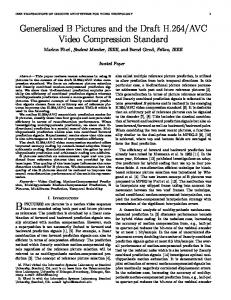
Fig. 1.
Intra Mode Decision
Functional blocks for H.264 intra frame encoder.
reference software[7] encoder utilizes a Lagrange cost function to make an intra-prediction mode decision. The cost for any given intra mode (J Mode ) is computed as follows: JMode (MBk , Ik |QP, λ Mode ) = D(MBk , Ik |QP) + λ Mode ∗ R(MBk , Ik |QP)
(1)
where λ Mode , D, and R represents the Lagrange parameter, Distortion, and Rate, respectively. The rate (R) for a given mode is estimated by the number of bits required to encode the current block. Similarly, the distortion (D) is computed using the Sum of Absolute Transformed Difference (SATD) or the Sum of Absolute Differences (SAD) of the residual block data. However, the SATD provides better encoding video quality as it is more precise in estimating the distortion of the encoded block. The H.264/AVC reference software computes the frequency domain coefficients for the candidate intraprediction mode by using the Hadamard transform. The absolute sum of all of these Hadamard transformed coefficients is taken as the distortion (D) in Eq.(1). The intra-prediction process of a current block requires the reconstructed pixels from the left and/or top neighbor blocks. Therefore, the intra-prediction process cannot be started until these reconstructed pixels of the neighbor blocks are available for prediction. The reconstruction process involves the forward integer transform (T), quantization (Q), inverse quantization (IQ) and inverse integer transform (IT) processing units. Consequently, low latency is an important requirement for all of these processing units for the development of an efficient intra-frame encoder. A number of optimized algorithms along with the corresponding architecture for the processing blocks in the intra-frame processing chain have been proposed in past few years. For instance, Jin. et al., [21] proposed an efficient algorithm for intra-prediction and mode decision process and was able to significantly reduce the complexity and computational load for these processing units. The algorithms proposed in the literature, however, either compute the partial cost of the prediction modes and/or restrict the number of possible candidate modes
The remainder of this paper is organized as follows. Section II presents the related work and background for the problem whereas Section III describes the proposed design in detail. Section IV presents our results compared to the existing state-of-the-art designs in the literature. Finally, Section V concludes this paper. II. BACKGROUND AND RELATED WORK The background knowledge for the H.264/AVC intraframe encoder is briefly described to highlight the problem. Subsequently, the related work in the literature is provided in this section. The functional block diagram of an H.264/AVC intraframe encoder is depicted in Fig. 1. The encoding loop of the H.264/AVC intra-frame encoder includes intramode prediction, forward integer transform (T), quantization (Q), inverse quantization (IQ) and inverse integer transform (IT) processing blocks. All of these processing blocks are on the critical path of the H.264/AVC intraframe encoder. The H.264/AVC video coding standard supports multiple intra prediction modes (4 modes for the 16 × 16 block type and 9 modes for the 4 × 4 block type). These multiple intra prediction modes help to significantly reduce the predictive error by exploiting the spatial correlation between the block to be encoded and its already encoded neighboring blocks. When a current block is to be encoded as an intra block, the prediction blocks for all of the possible supported intra-modes are formed using previously encoded and reconstructed blocks. These prediction blocks are then analyzed in the mode decision processing unit to determine the best intra prediction mode for the block at hand. The H.264/AVC 229 235
to zero. A typical transformed and quantized residual block contains few non-zero coefficients in the lowfrequency region and mostly zero-valued coefficients in the high-frequency region. For the inverse integer transform, while decoding the incoming video bit-stream in the decoder or during the (inverse) quantization process, it is already known for the given 4 × 4 block which transformed coefficients are non-zero and shall contribute to the pixel values for the reconstructed block. Therefore, a considerable amount of computations can be saved by exploiting this information while developing an algorithm for the inverse integer transform. In this presented work, we followed a different approach and derive a serial algorithm for the inverse integer transform unit using a direct 2-D transform approach. The hardware unit for the inverse integer transform, based on the serial processing algorithm, directly interfaces with the inverse quantization unit without requiring any additional buffer or delay. The inverse integer transform unit processes the incoming inverse quantized data items on-the-fly and accumulates its contribution towards the final values for the inverse integer transformed block or the residual block. Therefore, the latency penalty is significantly reduced with this approach. Additionally, if the incoming data-item is zero-valued, the processing for this particular data-item is skipped to avoid the unnecessary signal activity in the circuit.
by exploiting different characteristics (such as correlation, edge orientation, etc.) of the video block in the video frame. Similarly, the main focus of research, from the inverse integer transform processing unit point of view, has been to develop fast algorithms with minimal on-chip area requirement for its hardware implementation. In [8], the transpose operation for the 2-D 4 × 4 inverse integer transform is realized by use of a parallel register array whereas Cheng, et al., [9] proposed a high-throughput 4 × 4 inverse integer transform architecture with no transpose memory requirement. Fan, et al., [10] proposed a fast 2-D transform algorithm. Similarly in [11] - [13], a number of fast algorithms for the inverse integer transform were proposed. Since the H.264/AVC encoder utilizes multiple transforms (forward/inverse integer and Hadamard transforms), therefore, significant efforts were made to design a unified transform unit that supports all of the transforms in H.264/AVC [14]-[18]. The unified transform unit requires less chip area for its hardware implementation. The proposed architectures although support multiple transforms in H.264/AVC, but mostly provide only one type of transform at a time. These solutions are very efficient in terms of throughput and performance per unit area, however, their latency penalty in the intraframe encoding loop is quite large and varies from 4.92ns to as high as 16ns.
A. Inverse Integer Transform Algorithm
III. PROPOSED DESIGN
In the H.264/AVC video coding standard, for any 4 × 4 inverse quantized input block “X”, its corresponding residual pixel block “Y” is computed as follows:
In this section, we first describe our approach for the low-latency and area-efficient solution for the inverse integer transform unit. Subsequently, the algorithm and the corresponding architecture for the inverse integer transform unit are described. The typical implementation of the forward and the inverse quantization units, from the multiplier areareduction point of view, process the input data either serially or four data items in parallel. Similarly, the hardware unit for the inverse integer transform, depending upon the algorithm implemented, requires one-fourth, half, or a complete 4×4 input block of data to start its processing. Therefore, an additional buffer is required for pipeline implementation or a delay is to be introduced before the start of the inverse integer transform process. Moreover, most of the algorithms for the inverse integer transform assume that all of the 4 × 4 input block data-items are non-zero. Consequently, these algorithms perform constant number of operations per block to compute the inverse integer transform for the given block of data. In digital video coding, however, it is very common that a substantial number of spatial high frequency transformed coefficients of residual block are quantized
Y = Ci ∗ X ∗ CiT
(2)
where 1 1 Ci = 1 1
1 1/2 −1/2 −1
1 −1 −1 1
1/2 −1 1 −1/2
(3)
Thus, the corresponding direct 2-D inverse integer transform for Eq.(2) can be computed as follows: vec(Y) = (Ci ⊗ Ci ) ∗ vec(X)
(4)
In Eq. (4), “⊗” is the Kronecker product. “Vec(X)” is a column vector consisting of the inverse quantized data items as input and “Vec(Y)” represents the corresponding column vector with the inverse integer transform coefficients values as output of the direct 2-D computation approach. From Eqs.(3) and (4), we can write: 230 236
1 1 1 1 1 1 1 = 11 1 1 1 1 1 1 1
vec(Y)
1 1/2 ‐1/2 ‐1 1 1/2 ‐1/2 ‐1 1 1/2 ‐1/2 ‐1 1 1/2 ‐1/2 ‐1
1 ‐1 ‐1 1 1 ‐1 ‐1 1 1 ‐1 ‐1 1 1 ‐1 ‐1 1
1/2 ‐1 1 ‐1/2 1/2 ‐1 1 ‐1/2 1/2 ‐1 1 ‐1/2 1/2 ‐1 1 ‐1/2
1 1 1 1 1/2 1/2 1/2 1/2 ‐1/2 ‐1/2 ‐1/2 ‐1/2 ‐1 ‐1 ‐1 ‐1
1 1/2 ‐1/2 ‐1 1/2 1/4 ‐1/4 ‐1/2 ‐1/2 ‐1/4 1/4 1/2 ‐1 ‐1/2 1/2 1
1 ‐1 ‐1 1 1/2 ‐1/2 ‐1/2 1/2 ‐1/2 1/2 1/2 ‐1/2 ‐1 1 1 ‐1
1/2 ‐1 1 ‐1/2 1/4 ‐1/2 1/2 ‐1/4 ‐1/4 1/2 ‐1/2 1/4 ‐1/2 1 ‐1 1/2
1 1 1 1 ‐1 ‐1 ‐1 ‐1 ‐1 ‐1 ‐1 ‐1 1 1 1 1
1 1/2 ‐1/2 ‐1 ‐1 ‐1/2 1/2 1 ‐1 ‐1/2 1/2 1 1 1/2 ‐1/2 ‐1
1 ‐1 ‐1 1 ‐1 1 1 ‐1 ‐1 1 1 ‐1 1 ‐1 ‐1 1
1/2 ‐1 1 ‐1/2 ‐1/2 1 ‐1 1/2 ‐1/2 1 ‐1 1/2 1/2 ‐1 1 ‐1/2
1/2 1/2 1/2 1/2 ‐1 ‐1 ‐1 ‐1 1 1 1 1 ‐1/2 ‐1/2 ‐1/2 ‐1/2
1/2 1/4 ‐1/4 ‐1/2 ‐1 ‐1/2 1/2 1 1 1/2 ‐1/2 ‐1 ‐1/2 ‐1/4 1/4 1/2
1/2 ‐1/2 ‐1/2 1/2 ‐1 1 1 ‐1 1 ‐1 ‐1 1 ‐1/2 1/2 1/2 ‐1/2
1/4 ‐1/2 X00 1/2 X10 ‐1/4 X20 ‐1/2 X30 1 ‐1 X 01 1/2 * X11 …(5) 1/2 ‐1 X21 1 X 31 ‐1/2 ‐1/4 . . 1/2 . ‐1/2 1/4 X33
InReg X val
P0
Y0
P1
Y1
P2
Y2
ENABLE Ctrl
Control Block
X Position (I,j)
Ctrl
Ctrl
Eq.(5) suggests that the residual pixel block “Y” can be computed by simply adding (or subtracting) the current (or scaled by 1/2, or 1/4) value of any given input coefficient “Xi j ” to the accumulated values for the out put block data-items “Yi j ”. Therefore, the serial inverse integer transform algorithm requires one register to hold the incoming input data-item for its hardware implementation and 16 registers to hold the partial (or accumulated) results for the out put block data-items “Yi j ”. Similarly, 16 add/sub units are required to add the current (or scaled) value to the already accumulated partial results. The accumulator is initialized to zero at the start of each input block. As soon as the last data-item of the input block arrives, the corresponding residual pixel block “Y” is available at the output of the inverse integer transform unit. Therefore, with this approach, the inverse quantized data items “Xi j ” from the inverse quantization unit are processed on-the-fly without introducing any delay for the computation of the residual pixel block. Moreover, only the non-zero input dataitems are stored in the input register of the inverse integer transform unit for processing. This helps to reduce the un-necessary signal activity in the circuit which can, therefore, contribute to potentially reduce the dynamic power consumption especially at coarser quantization parameter (Q p )value and/or smoother regions of the video frame being processed.
Fig. 2.
P15
Y15
Functional Block Diagram.
Acc
RESET Mux X from InReg 1/2
Add / Sub
Yn
1/4
MuxCtrl Add/Sub Ctrl
Fig. 3.
Internal Architecture of “P” Block.
accumulated partial result on the basis of control signals from the control block. The internal architecture of “P x ” block is depicted in Fig. 3. This block consists of one multiplexer “Mux” at the input, one accumulator register “Acc”, and one “Add/Sub” unit. The multiplexer is used to select the correct contribution of the input dataitem for any particular “Yi j ” where as “Acc” register holds the partial results during processing. The “Acc” register is initialized to zero at the start of a new input block for the inverse integer transform using “RESET” control signal. The control block in Fig. 2 generates signals to control the data flow in the processing unit for the computation of the inverse integer transform. The control signals for “Mux” and “Add/Sub” can be straightforwardly derived from Eq.(5). The “ENABLE” control is used to provide the gated clock to the “InReg”. The generation of “ENABLE” and “RESET” control signal is depicted in Fig.4.
B. Architecture of the Inverse Integer Transform Unit The functional block diagram of the hardware implementation of the proposed inverse integer transform algorithm is depicted in Fig. 2. The unit takes the current inverse quantized coefficients “X val” as input along with its position in the input block. This value is stored in the register “InReg” (Fig. 2) only if it is non-zero. The “P x ” processing blocks holds the partial (or final) value of each residual pixel bock data-item “Yi j ” and, therefore, are 16 in number. These blocks “P x ” process the value stored in the “InReg” along with the already
231 237
TABLE I P ERFORMANCE COMPARISON TABLE . Technology (µm) DPRa (pixels/cycle) Transpose/Permutation Speed (MHz) Agg. Throughput(4×4 blocks/s) Area (gates) Latency (ns)
Cheng [9] 0.35 8 Permutation 86 (189*) 5.38 (11.81*) 3377b 11.66 (5.30*)
Lin [18] 0.35 8 Permutation 56 (137*) 3.50 (8.56*) 8264b 16.08 (7.31*)
Wang [25] 0.35 4 Transpose 125 (266*) 7.81 (16.63*) 4424bc 8.27 (3.76*)
Chen [24] 0.18 16 Permutation 166 10.38 7497b 6.02
Woong [22] 0.18 16 Permutation 203 12.69 5639b 4.92
Proposed 0.18 1 Permutation 375 23.44 7512 2.67
a: Data processing rate; b: Requires an additional interface buffer (area NOT included); c: Requires a transpose buffer (area NOT included); *: Values computed with scale factor 2.2
and a comparison with other designs is provided in Table I. The latency penalty for our design cannot be compared directly with those of [9], [18], and [25], because of different process technology. The scale factors for a set of different latest process technologies are provided in [26]. However, it does not provide a scale factor for 0.18µm and 0.35µm technologies. Since a scale factor of 2.2 exist among technologies like (80nm and 40nm), and (70nm and 36nm). Therefore, we assume the same scale factor to compare the latency penalty of our design with those of [9], [18], and [25]. The comparison shows that the proposed design provides the minimum latency penalty (2.67ns) among all designs. The comparison table also provides the aggregated throughput of all of these designs of inverse integer transform unit when interfaced with Inverse Quantization (IQ) processing unit. It is assumed that the Inverse Quantization (IQ) processing unit operates at the same maximum operating frequency as that of the corresponding design. From Table I, we suggest that the proposed design provides the highest throughput among all designs. The throughput of other designs can be improved by providing 4, 8, or 16 data items in parallel. However, this approach cost additional chip area for Quantization (Q) and Inverse Quantization (IQ) processing units with same scale factor (i.e., 4, 8, or 16).
X val ENABLE
X Position Position(0,0)
Fig. 4.
CMP
RESET
ENABLE, RESET signals generation.
IV. DESIGN EVALUATION The design described in this paper for the inverse integer transform was modeled in VHDL and synthesized by the Synopsys Design Compiler (version v2002, rev. 05) for a maximum operating frequency of 375 MHz with 0.18µ m CMOS standard cell technology (v1.5). The implementation was verified by simulation results generated using ModelSim 6.5 and comparing with that of JM13.2 reference software [7]. The area requirement for the hardware implementation of the proposed design in terms of equivalent gate count is 7512, whereas the latency is only 2.67 ns. The proposed design with a maximum operating frequency of 375 MHz, therefore, can easily meet the throughput requirement of the real-time processing of HDTV (1920 × 1080, 16 : 9, 30 frame per second) with an operating frequency as low as 94 MHz. The comparison with other state-of-the-art designs in literature is provided in Table I. The proposed design requires significantly less area (7512 gates) in terms of equivalent gate count for its hardware implementation. It should be noted that all other designs require one or more additional buffers to interface with the inverse quantization processing unit in the intra-frame processing chain. Therefore, they require additional chip area for interface, whereas our proposed design does not require such buffers because of the fact that it processes the input data-items on-the-fly and therefore, requires only a single 16-bit register (it is included in 7512 gates). The latency penalty of the proposed design is 2.67ns
V. CONCLUSION We proposed a low-latency, area-efficient design for the inverse integer transform in H.264/AVC. The lowlatency design is particularly targeted for real-time video processing applications with intra-only encoding mode such as television studio broadcast. The area requirement is reduced by using a serial inverse integer transform algorithm with no input buffer requirement and the latency penalty is reduced because of on-the-fly processing of the input data-items with relatively simplified data path. The proposed design synthesized under 0.18µm CMOS standard cell technology has a latency penalty of 2.67ns and consumes only 7512 gates. The maximum operating frequency is 375 MHz and therefore, it can easily meet the throughput requirement of the real-time processing 232 238
of HDTV (1920×1080, 16 : 9, 30 frame per second) with an operating frequency as low as 94 MHz.
[14] C. P. Fan. “Cost-effective Hardware Sharing Architectures of Fast 8x8 and 4x4 Integer Transforms for H.264/AVC”. In IEEE Asia Pacific Conference on Circuits and Systems, pp. 776–779, 2006. [15] W. Hwangbo, and C. M. Kyung. “A Multitransform Architecture for H.264/AVC High-Profile Coders”. In IEEE Transactions on Multimedia, vol. 12, no. 3, 2010. [16] C. Y. Huang, L. F. Chen, and Y. K. Lai. “A High-speed 2-D Transform Architecture with Unique Kernel for Multi-standard Video Applications”. In IEEE International Symposium on Circuits and Systems(ISCAS),pp. 21–24, 2008. [17] Y. Li, Y. He, and S. Mei. “A Highly Parallel Joint VLSI Architecture for Transforms in H.264/AVC”. In Journal of Signal Processing Systems,vol. 50, no. 1, pp. 19–32, 2008. [18] H. Y. Lin, Y. C. Chao, C. H. Chen, B. D. Liu, and J. F. Yang. “Combined 2-D transform and Quantization Architectures for H.264 Video Coders”. In IEEE International Symposium on Circuits and Systems(ISCAS),pp. 1802– 1805, 2005. [19] H. S. Malvar, A. Hallapuro, M. Karczewicz, and L. Kerofsky. “Lowcomplexity Transform and Quantization in H.264/AVC”. In IEEE Transaction on Circuits and Systems for Video Technology, vol. 13, no. 7, pp. 598–603, 2003. [20] D. Marpe, V. George, H. L. Cycon, and K. U. Barthel. “Performance Evaluation of Motion-JPEG2000 in Comparison with H.264/AVC Operated in Pure Intra Coding Mode”. In SPEI Conference on Wavelet Applications in Industrial Processing, pp. 129–137, 2003 [21] G. jin, and H. J. Lee. “A Parallel and Pipelined Execution of H.264/AVC Intra Prediction”. In IEEE International Conference on Computer and Information Technology(CIT), pp. 246–251, 2006 [22] W. Hwangbo, J. Kim, and C. Kyung. “A High-Performance 2-D Inverse Transform Architecture for the H.264/AVC Decoder”. In International Symposium on Circuits and Systems, pp. 1613–1616, 2007. [23] M. Nadeem, S. Wong, and G. Kuzmanov. “An Efficient Realization of Forward Integer Transform in H.264/AVC Intra-frame Encoder”. In International Conference on Embedded Computer Systems: Architectures, Modeling and Simulations (SAMOS), pp. 71–78, 2010. [24] K. Chen, J. Guo, K. Chao, J. Wang, and Y. Chu. “A High-performance Low Power Direct 2-D Transform Coding IP Design for MPEG-4 AVC/H.264 with a Switching Power Supperssion Technique”. In International Symposium on VLSI Design, Automation, and Test, pp. 291–294, 2005. [25] T. Wang, Y. Huang, H. Fang, and L. Chen. “Parallel 4×4 2D Transform and Inverse Transform Architectures for MPEG-4 AVC/H.264”. In International Symposium on Circuits and Systems , pp. 800–803, 2003. [26] International Technology Roadmap for Semiconductors. http://www.itrs.net/.
R EFERENCES [1] [1] ITU-T Rec. H.264 and ISO/IEC 14496-10:2005 (E) (MPEG-4 AVC). “Advanced Video Coding for Generic Audiovisual Services”, 2005. [2] ISO/IEC JTC1/SC29/WG11. “Report of the Formal Verification Tests on H.264/AVC”. In doc. N6231, Waikoloa, USA, 2003. [3] [3] G. Sullivan, P. Topiwala, and A. Luthra. “The H.264/AVC Advanced Video Coding Standard: Overview and Introduction to the Fidelity Range Extensions”. In SPIE Conference On Applications of Digital Image Processing, vol. 558 pp. 454–474. 2004. [4] [4] J. Ostermann, J. Bormans, P. List, D. Maroe, M. Narroschke, F. Pereira, T. Stockhammer, and T. Wedi. “Video Coding with H.264/AVC: Tools, Performance and Complexity”. In IEEE Circuit and Systems Magazine, vol. 4 pp. 7–28. 2004. [5] [5] G. L. Foresti, P. Mahonen, and C. S. Regazzoni. “Multimedia VideoBased Surveillance Systems: Requirements, Issues and Solutions”. In Kluwer Academic Publishers, ISBN 0-7923-7927-6, 2000. [6] Y. W. Huang, B. Y. Hsieh, T. C. Chen, and L. G. Chen. “Analysis, Fast Algorithm, and VLSI Architecture Design for H.264/AVC Intra Frame Coder”. In IEEE Transaction on Circuit and Systems for Video Technology (CSVT), vol. 15, no. 3, pp. 378–401. 2005. [7] Reference Software for H.264 codec JM 13.2. http://iphome.hhi.de/suehring/tml/index.htm. [8] L. Z. Liu, Q. Lin, M. T. Rong, and J. Li. “A 2-D Forward/Inverse Integer Transform Processor for H.264 based on Highly-Parallel Architecture”. In IEEE Int. Workshop on System-on-Chip for Real-Time Applications, pp. 158– 161, 2004. [9] Z. Y. Cheng, C. Chen, B. D. Liu, and J. F. Yang. “High Throughput 2-D Transform Architectures for H.264 Advanced Video Coders”. In Proc. IEEE Asia-Pacific Conference on Circuits and Systems, pp. 1141–1144, 2004. [10] C. P. Fan. “Fast 2-Dimensional 4x4 Forward Integer Transform Implementation for H.264/AVC”. In IEEE Transactions on Circuit and Systems II , vol. 53, no. 3, pp. 174–177. 2006. [11] T. C. Wang, Y. W. Huang, H. C. Fang, and L. G. Chen. “Parallel 4×4 2D Transform and Inverse Transform Architecture for MPEG-4 AVC/H.264”. In Proc. IEEE International Symposium on Circuits and Systems, pp. 800–803, 2003. [12] K. H. Chen, J. I. Guo, and J. S. Wang. “A High-Performance Direct 2-D Transform IP Design for MPEG-4 AVC/H.264”. In IEEE Transaction on Circuits and Systems for Video Technology, vol. 16 pp. 472–483, 2006. [13] R. C. Kordasiewics, and S. Shirani. “ASIC and FPGA Implementations of H.264 DCT and Quantization Blocks”. In IEEE International Conference on Image Processing (ICIP), vol. 3, pp. 1020–1023, 2005.
233 239