Robust Approach for Supporting Inter-Application Communication and Device Handling in Integrated Modular Avionics Mohamed Younis
Mohamed Aboutabl
Daeyoung Kim
Dept. of Computer Science and Elec. Eng. University of Maryland Baltimore County Baltimore, MD 21250
[email protected]
Wireless Network Group Lucent Technologies Mt. Olive, NJ 07828
[email protected]
Dept. of Computer Science & Eng. Arizona State University Tempe, AZ 85287
[email protected]
Abstract Integration of multiple real-time control modules has gained increased acceptance as a new trend in the industry during the past few years. For example, the avionics industry is embracing a new design approach referred to as Integrated Modular Avionics (IMA) that encourages resource sharing to minimize the development and maintenance costs of avionics. However, the IMA approach also brings new challenges that do not exist in a federated implementation of avionics. Avoiding unwanted dependencies among applications and managing the reuse of legacy applications tops the list of challenges. This paper describes techniques for inter-application communication and handling of I/O devices that facilitates the integration of applications in an IMA system. These techniques enable the integration of multiple applications while maintaining strong spatial and temporal partitioning between application software modules. The presented approach is lock-free requiring the least support from the operating system and minimizes the dependency of the integrated environment on application characteristics. Keywords: Inter-application communication, Integrated Modular Avionics, Strong Partitioning, Lockfree Synchronization, Fault Containment.
1. Introduction The increased processing and communication power of modern computers motivated new design approach for avionics. In the new approach, which is called Integrated Modular Avionics (IMA) [1], multiple federated applications would be combined into a shared platform. The IMA design concept encourages the integration of multiple software components into a shared computing environment powerful enough to meet the computing demands of these traditionally separated components. Such integration has many economical advantages for airplane operation, including lower hardware costs, reduced level of spares, lighter avionics' weight and lower power consumption. The Integrated Hazard Avoidance System (IHAS) and the Integrated Environmental Control System (IECS) are examples of IMA systems being considered in the industry. The IHAS system integrates flight safety avionics such as Traffic Collision Avoidance System (TCAS), Enhanced Ground Proximity Warning System (EGPWS) and Weather Radar. The IECS system controls the operating environment to ensure safe use of the equipment on the aircraft and the comfort of passengers. For example, the IECS system adjusts (by cooling or heating) the operating temperature of hydraulic, electrical and mechanical power devices and equipment, de-ices and defogs windshield and controls cabin pressure and passengers’ air-condition. The 1
IHAS and IECS systems achieve substantial reduction in the expensive flight-worthy hardware, in the weight and volume of the avionics and in the power consumption. Such reduction lowers the cost of avionics and increases the efficiency of aircraft operation. However, such integration complicates the design and validation of these systems since sharing resources makes the behavior of the integrated application hard to predict and guarantee, and therefore ensuring the fulfillment of timing constraints and maintaining fault-tolerance becomes a challenge. For safety-critical real-time applications, it is necessary to be able to show, with a high level of assurance, that a problem or failure in one application cannot disrupt or corrupt other applications. Thus, the IMA approach inherently requires strong partitioning among the different modules coexisting within the same system. Strong partitioning calls for well-defined boundaries among modules to ensure the continuity of operation in the presence of partial failure [2]. Containing the effects of faults is crucial for the integrated environment to guarantee that a faulty module may not cause other modules to fail and risk generating a total system failure. Strong partitioning also facilitates the modification, debugging, integration, and certification of the modules involved in building a system with the level of complexity found in the avionics industry. On the other hand, achieving time and space separation among the integrated applications should not limit applications’ ability to communicate and share data. In fact, the integrated applications would even require increased inter-application communication since the integration of traditionally federated applications allows exploring additional synergy among them and thus leading to enhanced functionality [1,2]. However sharing data and device access post a challenge for strong partitioning and if not carefully supported can violate the fault containment goal of the IMA. For example, an application should not be allowed to erroneously lock access to a device or corrupt shared memory area. This paper describes techniques for inter-application communication and handling of I/O devices in an IMA system. These techniques enable the integration of multiple applications while maintaining strong spatial and temporal partitioning between application modules. Two applications communicate with each other while being spatially protected against any erroneous behavior that can result in corrupting their memory space. The techniques are lock-free [3] and thus prevent one application from hindering the progress of another. Integration of application modules is simplified by abstracting the desired interactions among the applications as device access transactions. Such abstraction facilitates the integration of previously developed application in the IMA environment. The approach requires less support from the operating system compared with lock-based approaches [13] and minimizes the dependency of the integrated environment on details of the applications. The following subsection defines strong partitioning and the fault model assumed. The rest of this section includes a brief overview of the software architecture for the IMA system, used as a reference while describing our techniques, and a discussion of related work. Section 2 describes our approach for robust 2
inter-application communication among integrated software modules. Section 3 describes techniques for handling input/output devices while maintaining strong partitioning. Section 4 describes the implementation environment. Finally, section 5 concludes the paper. 1.1 Strong Partitioning of Software Strong or robust partitioning conceptually means that the boundaries among applications are well defined and protected so that the behavior of an application module will not be disrupted nor corrupted by the behavior of another [2], even if the other application is operating in an erroneous or malicious way. Containing the effects of faults is crucial for the integrated environment to guarantee that a faulty module cannot cause other modules to fail and risk generating a total system failure. For instance, in an ideal IMAbased avionics system, a failure in the cabin’s temperature control system must not negatively influence critical flight control systems required for safe operation of the aircraft. In a federated avionics system, applications do not share processors or communications hardware with each other and partitioning comes naturally, but the cost is high because of the exclusive use of computing resources. In an IMA environment, an application will frequently share a resource with other applications and thus its correct operation becomes dependent on the correct sharing of the resource. When multiple avionics software application coexist on the same computer, partitioning is particularly challenged in the way applications access memory, consume CPU processing cycles and interface with input and output devices. Usually applications are allocated different memory regions while the usage of shared resources such as the CPU and I/O devices are arbitrated among them based on a time schedule. The memory partitioning and time schedules are usually determined as part of the integration of the applications into a system. Although dividing memory and resource capacity among several applications forms boundaries and facilitates the integration, it cannot guarantee that those boundaries will not be violated when faults exist. Therefore, the IMA environment needs to ensure strong partitioning among the integrated applications both spatially and temporally. The address space of each application must be protected against unauthorized access by other applications. In addition, an application should not be allowed to overrun its allocated quota of CPU time usage and delay the progress of other integrated applications. This paper focuses only on ensuring spatial partitioning while enabling communication and device sharing among the integrated applications. We rely on the availability of a memory protection mechanism to define memory partitions and control the read, write, and/or execute access to these memory partitions. It is worth noting that the memory management unit is almost standard on commercially available computer boards serving the embedded applications industry.
3
Fault Model: Strong partitioning implies the fail silent model [4], that any erroneous behavior of a faulty module should not affect other healthy modules. The erroneous behavior of an application can be the result of a software fault or a failure in a hardware device used exclusively by that application. The fault can be generic, accidental or intentional in nature; it can be permanent, transient or intermittent in duration. However, we assume that there are application-specific semantic checks, which verify the validity of the communicated data to detect errors due semantic-related generic faults in the application software. We also assume that the system is not liable to Byzantine-type fault [4]. In addition, we assume that faults occur one at a time with no simultaneity. An attempt by a faulty module to corrupt other healthy modules should lead to a detected error. Only applications that communicate with that faulty application partition need to be aware of the error and perform recovery actions according to the nature of the application. On the other hand, operations of healthy applications that do not communicate with the faulty application will not be affected. 1.2 Two-Layer Software Architecture for IMA In this subsection, we briefly describe
a
novel
CPU Board
software
Application
architecture that we developed
App. Exec.
for integrating real-time safetycritical
avionics
Device Driver
applications.
Interface Lib.
Bus Driver CPU Board
The architecture, depicted in
System Executive
figure 1, is fundamentally a twolayer operating environment that Interconnection Bus
is able to comply with the
Figure 1: New Avionics Software Architecture
ARINC specification 653 [5] and
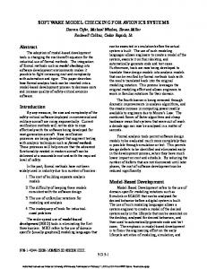
the Minimum Operational Performance Standards for Avionics Computer Resource [6]. However, our approach goes one step further by enabling the integration of legacy software modules together with their choice of real-time operating system, all executing on a shared CPU. Although the discussion of our approach for inter-application communication refers to this architecture, the techniques are also applicable to other IMA systems. The following is a summary of the functional components of the architecture. The reader is referred to [7] for a detailed discussion on the architecture and to [8] for an approach to scheduling applications in this setup. System Executive: The bottom layer of the architecture, termed the system executive (SE), provides each application module with a virtual machine [9], i.e. a protected partition, inside which the application can execute. This way, the application is isolated from other applications in the space domain (i.e. memory
4
address space). We rely on hardware means such as the memory management unit that is available with most modern processors to enforce spatial partitioning. Time-domain isolation is accomplished by sharing the CPU and other resources among applications based on a pre-computed static timetable. The system executive maintains a real-time clock to strictly implement the timetable in which each application is assigned well-defined time slices. In addition to ensuring spatial and temporal partitioning, the SE handles context switching, and initializes, monitors and terminates application partitions. Only the SE would have the ability to execute in the highest privileged CPU mode. All other partitions execute in a less privileged CPU mode thus ruling out the possibility of an application corrupting the memory protection set up or violating other applications’ rights to use the CPU. Application Executive: Each application, which may consist of multiple tasks, is assigned a protected memory partition, thus preventing a fault in one application partition from propagating to other applications. To accomplish this feature, each application is accompanied by its own application executive (AE) as well as an Interface Library (IL) to the system executive’s services. The AE handles intra-application communication and synchronization. The AE also manages the dynamic memory requirements of the application within the boundaries of the application’s own memory partition. The AE may also implement its own strategy for scheduling the application’s tasks. All of the AE’s functions related to inter-application and inter-processor communications are handed through the IL. It should be noted that the AE can be another operating system for which the application was originally written, yet with some of the more privileged capabilities rerouted to the SE via the IL, as described next. Interface Library: Since operating systems in general assume privileged access to the hardware, the system executive needs to provide services to the application executives that enable them to handle privileged operations [9]. These services include exception handling, interrupt enabling and disabling and access to processor internal state during task (thread) context switching. The interface library encapsulates these services and acts as a gateway between the AE and the computer’s hardware services. The main design goal for the two-layer architecture is to keep the SE simple and independent of the number and type of integrated applications. Simplicity of the SE design facilitates the certification. Being independent of the integrated applications makes the SE insensitive to changes to the applications and thus limits re-certification efforts to application changes or upgrades. The inter-application communication paradigm is one major aspect that determines the degree of coupling between the SE and the individual application partitions. Therefore, the mechanism for inter-application communication should avoid coupling the SE with the application to the greatest extent possible. Section 2 discusses a lock-free approach for interapplication communication that maintains strong partitioning among the integrated applications and allows communications without involving the SE. Throughout this discussion, the terms partition and application 5
are used interchangeably. It should be noted that the presented approach fits other two-layer IMA software architectures — not only the one discussed in this section. Before describing our approach we review related work. 1.3 Related Work Fundamental research related to lock-free synchronization can be traced back to the early time of distributed computing when Lamport developed a methodology based on the use of two version numbers at the beginning and the end of each message [10, 11]. The lack of locks raises the possibility of repetitive trial by the reader to get consistent message since it could be preempted before completely retrieving a message or trying to read incompletely written message. Mechanisms for lock-free synchronization can be generally classified depending on the number of readers and writers. We focus on the single-writer-single-reader and the single-writer-multiple-readers problems. Allowing multiple writers defies the strong partitioning goal of the IMA methodology. A lock-free mechanism is considered wait-free if the reader does not have to retry [12]. Although wait-free mechanisms sound attractive for real-time systems, they typically require the involvement of the operating system. Keeping the SE out of the inter-partition communication is a design goal and thus wait-free mechanisms were not considered. Due to the many advantages of lock-free synchronization for real-time software, particularly its avoidance of priority inversion problem [13], the effect of lock-free mechanisms on the schedulability of multi-threaded real-time systems has received increasing interest over the past few years. Anderson, et al. proved that the worst-case delay introduced by retry-loops when accessing shared data is bounded for famous fixed and dynamic priority scheduling disciplines [3]. In addition it was demonstrated that lock-free access to shared data incur less overhead compared to lock-based and wait-free mechanisms under these scheduling disciplines. Following the spirit of Lamport’s work in the use of versioning, Kopetz, and Reisinger have developed a time bound on the overall operation in order to derive a schedulability test and a formula for determining the required duplication in the message buffer so that the reader would not miss a message [14]. To avoid duplication in the message buffer, Chen and Burns allow the reader to indicate its status so that the writer will avoid the location in the buffer, which the reader is using [15]. For the multiple-reader case, they assume that the buffer is not updated sequentially and designate one copy per reader. Such approach is not applicable in the IMA environment since it allows the reader to have write-access to the buffer. Our approach, as explained in section 2, allows only one copy for the multi-reader case. We rely on an off-line partition scheduler to ensure that the reader application can consume the data at the appropriate rate. The Airplane Information Management System (AIMS) on board the Boeing 777 commercial airplane is among the few examples of IMA based systems [16]. Although the AIMS and other currently used modular avionics setup offer strong partitioning, they lack the ability of integrating legacy and third party’s applications. In our approach, a partition encompasses an operating system together with its application. All 6
previous IMA architectures have the application task(s) as the unit of partitioning. Other notable IMA work is performed within the GUARDS project [17]. However the focus of the work was mainly on configuring and synthesizing ultra-reliable systems and not integration of the applications. Given the contribution of this paper, work related to the environment and the kernel design is not discussed and the reader is referred to [7] for in depth comparison.
2. Inter-partition Communication Communication primitives are needed to share data among the various partitions. Generally, message passing and shared memory are used for inter-task communication in a multi-task setup. The same techniques are applicable to inter-partition communication. However, our approach only supports the use of message passing as a means for inter-partition communication (IPC) in an IMA environment. Shared memory is prone to error propagation since minimal checks are usually deployed to validate the data [18,19]. Meanwhile message passing is able to provide a robust communication means among partitions since rigorous message format checking can be imposed to guard against bogus traffic. In addition, well-known standards also recommend the use of message passing for IPC [5,6]. It should be noted that application tasks within a partition might still communicate with each other through the inter-task communication mechanisms provided by the AE. Only communication activities from one partition to the other are required to be through message passing. Regardless of the choice of the IPC communication approach, synchronization mechanisms have to be employed to serialize access to the shared data among the communicating partitions. Lock-based approaches, e.g. semaphores, have been widely used for synchronization. However such lock-based mechanisms require the involvement of the operating system, the SE in our environment. Involving the SE in the handling of inter-application messages increases the coupling between the applications and the SE and thus complicates the integration. The SE design is desired to be independent of the type and number of integrated applications so that it does not have to be re-certified with any slight changes in one application. In addition, lock-based mechanisms can cause multiple issues, such as priority inversion and deadlocks, and thus requiring even more sophisticated algorithms by the SE [13]. Since the simplicity of the SE is a main design goal, lock-free mechanisms for synchronization have been adopted.
Moreover, lock-free synchronization limits the
coupling among partitions and serves the IMA goal of achieving strong partitioning among the integrated applications. However, the lock free protocol must abide with the IMA spatial partitioning requirements. In other words, the IPC mechanism should not require one partition to have any write access to another partition. Typically, application partitions communicate in order to share data and services. If a partition P1 needs data from another partition P2, P1 either sends an explicit request to P2 to obtain the data or expects P2 to continuously make the data accessible to P1. Sharing services often requires exchange of request and 7
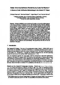
response messages between the requester (client) and the service provider (server). In our approach, we classify messages according to the communication semantics into request-response (client-server) messages and status messages. In client-server IPC, we allow only one server to receive requests from possibly multiple clients. Status messages are suitable for posting data, results of computation or readings of a streamed input device, e.g. a sensor. Implementation of status messages is simplified by assigning one writer partition and making the messages readable to designated partitions. The following subsections explain how client-server and status messages among partitions are supported. 2.1 Client-Server IPC Our approach calls for the allocation of a circular queue in the sender partition for
Application Partition (P2)
Application Partition (P1)
outgoing messages. The circular queue will be
Sender (client)
mapped, by the SE, to the address space of an Message
Re
authorized receiver partition for read-only
ad
Me
e ag ss
Receiver (server)
Read pointer
access. The sender partition is the only one that has a write access to the queue. The sender
Shared Memory (RO for P2 and R/W for P1)
Register and resolve addresses
Shared Memory (RO for P1 and R/W for P2)
partition maintains a read and a write pointer for the queue. The write pointer will be used to
Inter-partition Communication Facility
insert new messages. The read pointer is used to
System Executive
detect overflow conditions, as will be explained
Figure 2: Client-Server inter-partition message passing protocol
later. The receiver partition will maintain its own read pointer and ask the SE to make it readable to the sender partition. The client-server interactions are depicted in figure 2. To support multiple clients, multiple and separate channels will be established between each client and the server. The server will scan client queues in the order and frequency that are driven from the priority of the requests of each client. The receiver will use its read pointer to access messages from the sender’s queue. When the sender partition detects an overflow during message insertion, it removes those messages, if any, which the receiver has already consumed. The sender identifies the consumed messages by comparing the value of its version of the read pointer with the value of receiver’s read pointer. If the sender still experiences an overflow after updating its read pointer, an error should be declared and an application-specific action has to be taken. The read pointer of the receiver partition can also be used for acknowledgment, if needed. The sender partition can check the value of the read pointer of the receiver to ensure that a message (client’s request, for example) is being received by the server (receiver) partition. Although a lock-free synchronization suffers the disadvantage of potentially unknown number of repetitive read attempts [3,11], it is a non-issue in our approach. Since the client will detect overflow 8
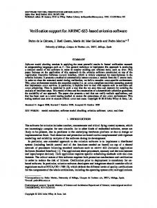
conditions and will not overwrite unconsumed requests, the server will repetitively attempt reading a request only when the client has not completely prepared his request and no other message is in the queue, i.e. queue is empty. In addition, according to the semantics of the communication, the server will not be affected since it can move on to handle requests from other partitions. The sender and the receiver apply the algorithms illustrated in figure 3. The write operation is completely local to the sender partition. The receiver’s read pointer will be advanced at the last stage of the read operation in order to protect the message from being accidentally overwritten. This case happens when the receiver is preempted before completely retrieving the message and the sender becomes short on vacant message entries in the queue. To prevent the receiver partition from reading an incomplete message due to Vacant (marked as invalid) buffer
Consumed (still marked as valid) msg
sndRd
sndRd: wt:
rcvRd
Sender's read pointer Sender's write pointer
wt
rcvRd:
Sender (client)
Unconsumed (marked as valid) msg
Receiver's read pointer
Receiver (server)
Initialization: set wt = sndRd = 0 ; For all i, set buf[i].status = INVALID ;
Initialization: set rcvRd = 0;
IPC_device_write( msg ) Begin next_wt = (wt + 1) modulo N ; If ( next_wt == sndRd ) /* possible overflow */ Begin If (sndRd == rcvRd ) /* definitely overflow */ return OVERFLOW ; Else Begin /* clean up consumed msgs */ For i=sndRd upto (rcvRd – 1) modulo N set buf[i].status = INVALID ; sndRd = rcvRd ; End End buf[wt].msgBody = msg ; set buf[wt].status = VALID ; wt = next_wt ; return SUCCESS ; End
IPC_device_read(msg) Begin If ( buf[rcvRd].status == VALID ) Begin msg = buf[rcvRd].msgBody ; rcvRd = (rcvRd + 1) modulo N; return SUCCESS ; End Else return UNDERFLOW ; End
Figure 3: Send and receive algorithms for client-server IPC
9
preemption of the sender partition, a binary status field is attached to each message indicating whether the message entry is used (valid) or not (empty). If the next entry to be read from the queue contains an empty message, the reader partition concludes that there is no message in the queue. The message status will be made valid only after if it is completely inserted in the queue. 2.2 Status Messages The previously described message-passing protocol fits a client-server model of inter-partition communication. However, this protocol becomes inefficient in case of broadcasting a stream of data, e.g. readings of sensors, to one or multiple partitions since the sender has to insert the message in multiple queues, one for each recipient. Alternatively a stream buffer of messages could be created by the sender partition in its own memory space and made readable to multiple recipients. The sender will be the only partition that has a writing permission to the stream buffer. The system executive will ensure that this stream buffer can be written only by the sender and maps the stream buffer to the memory space of one or several recipients as a read-only area. The stream buffer, as shown in figure 4, is circular with one write pointer maintained by the sender and a read pointer for each recipient.
Each
receiving
partition
Receiving Partition
t ou
out Sending Partition
is
responsible for maintaining its own read
in
Circular Message Buffer
Receiving Partition
out Receiving Partition
pointer. As depicted in figure 4, multiple Figure 4: Broadcasting stream of data messages
receivers might read from different location
within the circular stream buffer. Since there is only one stream buffer to be used by the sender and all recipients, tight control is needed to correctly handle concurrent read and write requests. One approach is to have the sender and receiver exclusively lock the message location in the stream buffer before writing or reading a message in order to ensure consistency if the partition is preempted. Locking will not only result in a considerable slowdown of the operation but also might introduce blocking conditions to the sender and recipient partitions. Alternatively, we apply a lock-free form of concurrency control. Each entry in the stream buffer has the following four fields: 1. A ‘message’ field where the message body is stored, 2. A ‘status’ field indicating whether the message is valid so that a recipient may retrieve it, 3. A message identifier used to distinguish old from recent messages. The identifier is the current value of a per-stream message sequence counter. 4. A cyclic redundancy check (CRC) to guard against reading an incompletely updated message (message reading is not assumed to be atomic). 10
The sender first invalidates the current message, then copies the message body augmented with the proper CRC, sets the message identifier to the current message sequence counter, sets the valid flag and finally increments the message sequence counter. Recipients first make sure that the current message is valid. Next they retrieve the message body and inspect the CRC code. If the recipient is preempted while retrieving a message and the sender inserts a new message in the same location with a new CRC then the recipient will detect that the CRC does not match the message body it just retrieved and may re-read the message. It should be noted that the CRC field might be replaced with any other check that ensures that the message is completely written. Although the fundamental issue can be classified as a single-writer multiple-reader lock-free synchronization, our approach differs from those reported in the literature. The use of versions and opposite order of reading and writing of shared structures, as reported in [11], will complicate the recovery from a partition failure. In addition our approach is easily scalable to handle traffic among applications that are not allocated to the same processor, e.g. shared memory multiprocessor architecture. Enforcing a reading order for a message across multiple processors can negatively affect the performance of the communication bus. Since the stream has multiple readers and a single writer, there might be wide variations in speed and frequency between the writer and one or several of the readers. Preventing the sender (writer) from posting messages because one receiver (reader) is slow might negatively affect other recipients. Therefore the sender partition would allow overwriting old messages by ignoring overflow conditions. Thus if a receiver got preempted and the sender overwrites the message that such a receiver was about to read, the receiver will retrieve out of sequence messages when it resumes execution, the first message is the most recently inserted one and the following message is the oldest message in the stream. The message sequence counter keeps track of the message writing order. By using the sequence counter for identifying the message, the reader partition can detect such subtle mix and can take an appropriate action. The size of the stream can be selected based on partition scheduling strategy so that no messages will be lost [14]. The inter-partition message service can be abstracted to the application tasks within a partition as a device driver. Using the device driver abstraction facilitates the integration of federated applications since they already have a means to communicate over external devices. In addition, only the device driver for the communication channel used by a federated application needs to be replaced for the application to communicate in the integrated environment. 2.3 Role of System Executive Minimizing the role of the SE in inter-partition communication is a design goal. Tightly coupling the SE with the integrated applications can mandate the re-certification of the SE with slight changes in the
11
applications. The described IPC approach does not involve the SE in IPC transactions, however it requires the help of the SE in the setup of IPC channels/streams and handling the failure of a partition. Managing IPC channel/stream registry: Since the SE manages system’s memory and guards spatial partitioning, the sender partition needs to register the queue address with the SE. In addition, the receiver partition has to register the location of its read pointer for that queue. The registration can be performed either during system initialization or at link time. In both cases the SE will maintain a list of the addresses of all IPC-related data structures. Registering the addresses during system’s initialization requires invocation of SE’s library routines in order to access the SE’s address space. After the registration both the sender and receiver partitions should query the list for the addresses of the read pointer and queue respectively. A partition needs to statically allocate a queue in its own address space to host
Queue Name
messages it sends to another partition. The partition is required to register that
Queue Address
Message No. Size Msg
Sender Authorized Part. ID Receiver
Msg Ack
Channels
queue to make the IPC service within the SE aware of the queue address and of the
! ! !
partition that is authorized to receive messages from this queue. The SE
Figure 5: The structure of the IPC channels registry table in the SE
maintains an IPC channel/stream registry table for all open IPC channels/streams (figure 5). The registry table is accessible for read-only by the application partitions. Recovery from Partition Failure: It is essential for application partitions to be aware of the failure of any partition with which they communicate. Although it is up to the application partitions to perform necessary recovery procedures in reaction to a failure of a communicating partition, generally at least the read pointers need to be reset. Since the read pointers can be updated only by the receiving partitions, solutions that make the recovery of a faulty sender partition transparent to the communicating partitions cannot be used. Two possible approaches for informing receivers of the failure of a sender partition could be identified. The first approach is to trigger some abnormal IPC condition so that the receiving partitions can detect the failure of the sender. The SE can either invalidate the partition IPC area or make it temporarily inaccessible to other partitions. Thus, the other applications could detect an error when communicating with the faulty partition. However, this approach has a fundamental problem that limits its use. The problem surfaces when the recovery and re-initialization of the faulty partition is completed before every receiving partition performs an IPC activity with the faulty partition and experiences the erroneous condition. In this case some of the receiving partitions will not be aware of the sender’s failure and will not reset their read pointers. Thus, this approach is being excluded as an option. 12
The second approach, which we adopt, requires the SE to maintain a health status history for every partition. The SE saves the health status of partitions in a shared memory area with read-only access to all partitions. In order for a receiver application to detect the failure of the sender partition, the receiver needs to check the status of the partition prior to each IPC activity. In case the receiver gets preempted during an IPC operation and the sender fails before the receiver resumes, one of two scenarios can take place. In the first scenario, the receiver reads a corrupt message indicating the failure of the sender or forcing an IPC retry that re-check the sender’s status. The second scenario allows the receiver to complete reading the message correctly before the sender is initialized, and thus delays the detection of the sender’s failure until retrieving the next message. Both scenarios allow the receiver to detect the failure of the sender. The failure history of a partition can be represented with two integer values. The first value indicates the number of times the sending partition has failed so far; the second reflects the current status of the partition. Each receiver needs to maintain its own copy of a value for the number of times the sender partition has failed. This private value is compared with the value maintained by the SE for this particular sender. If the two values match, the sender would be healthy. If the SE presents a larger count, the receiver would conclude that a failure has occurred in the sender and would be able to trigger a recovery procedure. Recovery actions include application specific procedures, updating its own value of the sender’s failure repetition to match the value presented by the SE and resetting the read pointer. The second value reflects the status of the partition (ready, being terminated or being initialized). In this way the receiver can know the sender is healthy before resuming (or continuing) IPC activities with that sender. This approach is easy to implement and does not require the SE to participate in the complicated and time-consuming data movement portions of IPC activities. Since the SE logs errors and monitors partition status, providing senders’ status is as simple as making it readable to the receiver partition.
3. Input and Output Handling Generally, the handling of input and output (I/O) is hardware-dependent. Typically, operating systems abstract an I/O device by a software driver, which manages the device hardware while performing input or output operations. The device driver provides a high-level interface for application tasks that need access to the device. Since I/O devices can be shareable, they can be an indirect means for fault propagation among partitions in our environment. For example, a partition that erroneously locks an input device might hinder the device’s availability to other healthy partitions and thus disrupt their operation. In addition, the two-layer architecture raises multiple issues on how the application will get access to the device. In the following sections we discuss these issues and define our approach for handling I/O devices.
13
3.1 Device Model Typically I/O devices can be classified into two types; polling-based and interrupt-driven devices. In pollingbased I/O the device is accessible upon demand and does not notify the application of data availability. An interrupt-driven device generates an interrupt when it has completed a previously started operation. The generated interrupt can be handled either by the CPU or by a dedicated device controller. Both types of devices can be either memory-mapped or IO–mapped. In memory-mapped I/O, regular memory-read and write instructions are used to access the device. Special I/O instructions are used for IO-mapped device access. In our environment, we assume that the CPU will not receive any interrupts from I/O devices. The I/O device should be either polled or supported by a device controller that is included in the device-specific hardware for access handshaking and data buffering.
In safety-critical real-time applications such as
avionics, frequent interrupts generated by I/O devices to the CPU reduce the system predictability and greatly complicate system validation and certification. In addition, the use of a device controller or I/O coprocessor is common on modern computer architectures to off-load the CPU and boost the performance. We also assume that the CPU either supports memory-mapped I/O or provides mechanism to enable partition-level access protection for IO-mapped devices. In all cases, access to I/O devices should not require the use of privileged instructions. In recent years, support of memory-mapped I/O devices has become almost standard on microprocessors. For example, the Motorola PowerPC processor supports memorymapped devices only. Using the memory management unit, access to a memory-mapped device can be controlled by restricting the mapping of the device address. A partition can access the device using regular memory access instructions if the device address is in its address space. On the other hand, the Intel Pentium processor supports both memory-mapped and IO-mapped devices. However, the I/O instructions of the Pentium processor are privileged. Thus only memory-mapped devices are allowed if the Pentium processor is used in our environment. 3.2 Device Handling Device handling in our approach can be performed within either the SE or the AE. Handling I/O devices within the SE will require the implementation of synchronization mechanisms to maintain correct order of operations among the applications and thus complicate the design of the SE. Maintaining the simplicity of the SE is a design goal in order to facilitate the SE certification. In addition, including device handlers in the SE makes the SE sensitive to device changes. Such dependency might mandate the re-certification of the SE every time a new device is added or removed. On the other hand, application executives cannot handle shared I/O devices without coordination among themselves. Our approach is to allow the AE to handle I/O devices that are exclusively used by that application (partition). The AE synchronization primitives can be used to manage access to a device made by tasks 14
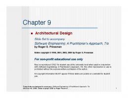
within the partition. The SE will ensure that every device in the system is mapped to one and only one partition. In order to support a shared device among partitions such as a backplane data bus, a device daemon (handler) will be created in a dedicated partition. The device daemon then “serves” access requests to that device made by the other application partitions. The shared device manager partition still has exclusive access to the device. Application partitions that need read or write access to a shared device communicate with the device daemon partition via IPC primitives. Devices that allow read/write (e.g. backplane bus), random read (e.g. a disk) or write-only (e.g. actuator) types of access require the use of client-server IPC protocol for communication among the device daemon and application partitions. In this case, the device daemon serializes requests from different partitions to maintain predictable and synchronized device access patterns. For stream input devices such as sensors, IPC streams (status buffers) can be used by the device daemon to make the input data available to other partitions. The partition that manages the shared device can perform only device handling or it can also host an application in addition to processing device access requests. In other words a partition, which controls a device, manages access to the device among its own internal tasks and can still serve access request from other partitions. For a heavily used shared-device, the dedicated device partition typically contains only the device daemon in order to ensure responsiveness. Managing a shared device by a partition that hosts other application tasks involves some risk since it introduces dependencies between partitions that require device access and the application partition that hosts the daemon for that device. If a failure of an application task causes the whole partition to crash, the shared device no longer becomes accessible to the other partitions. Since this configuration may threaten the system partitioning, it should not be used unless losing access to the device will not cause other partitions to fail. Abstracting device access via IPC primitives simplifies the integration of applications through routing messages among applications transparently, whether they are allocated to the same processor or to different processors. The developer consistently refers to applications using IPC channels/streams. IPC primitives, as discussed, can abstract communication with a device or with another application partition. In addition, our approach facilitates the integration of legacy applications designed originally for a federated system since they generally will not require excessive adaptation to use the IPC communications model. 3.3 An Example An example for our approach for device handling is shown in figure 6. Two partitions P1 and P2 are integrated in the system. The first partition (P1) needs frequent access to output devices D1 and D3 and occasional access to the output device D2. Partition P2 needs heavy access to devices D2 and D3. In the integrated environment a dedicated partition P3 is included to manage the shared device D3 and to serve requests made by P1 and P2. Partition P3 has an exclusive access to D3 and includes a daemon task and a device driver for D3. The device driver abstracts the device hardware and can be part of the daemon or as a 15
Application Partition (P2)
separate library. Typically, the driver is supplied by the device manufacture. The daemon task receives incoming access requests from other partitions by
Application Partition (P1)
reading from dedicated request queues (IPC_queue)
Task P1- A
Task P1- B
Device Driver (D1)
Task P2- C
Shared Device Partition (P3) D3 device daemon
D2 device daemon
allocated in a readable shared memory area. Partitions P1 and P2 use the IPC client-server
Task P2- B
Task P2- A
Device Driver (D3)
Device Driver (D2)
message passing protocol described earlier to communicate with the shared device partition P3.
readPtr P2,3 (RO for P2 and R/W for P1)
(RO for P3 and R/W for P2)
(RO for P2 and R/W for P3)
readPtr P1,2
Partition P1 has an exclusive access to D1, which (RO for P3 and R/W for P1)
is not shared with other partitions. Since D2 is shared between P1 and P2, a device daemon is needed. A dedicated partition could have been
(RO for P1 and R/W for P2)
readPtr P1,3 (RO for P2 and R/W for P3)
Inter-partition Message Handler
System Executive Figure 6: Handling of output devices
included to manage D2. Alternatively, D2 was allocated to P2 since P1’s access to D2 is significantly less frequent than P2. Access requests to D2 from P1 and from tasks within P2 have to be queued for service by the D2 device daemon. As shown in figure 6, tasks within the partition P2 use a separate queue to send requests to the device D2 daemon and another queue is assigned for requests from partition P1. The use of two separate queues decreases the dependencies between partitions P1 and P2. It should be noted that a dedicated partition has to be used if D2 is a critical resource. In the example it is assumed that only one task per partition needs access to a shared device managed by another partition, e.g. only task P1-B accesses device D2. If multiple tasks per partition need to have access to a shared device among partitions, The AE needs to manage the access order and the priority of requests within the partition. For simplicity, the figure depicts only the device-write scenario. A stream buffer or an additional queue will be needed at the device partition (e.g. P3) for reading data from the shared device. Our approach to device handling enables great flexibility in scheduling access requests to the shared device by decreasing the coupling between scheduling of application tasks and shared devices and thus simplifying schedulability analysis. In addition, having the device daemon allocated to a dedicated partition ensures fault containment among the partitions, protects the application partitions from errors in the device driver and facilitates debugging. Again through this approach the SE will have little to do with I/O handling and will maintain its intended simplicity. Using the shared device daemon approach, the system integrator needs to schedule the daemon partition as an integral part of the application partitions and to consider it in the schedulability analysis [20] to ensure timeliness under worst-case scenarios. Increased device access requests might mandate invoking the daemon partition for that device at a high frequency to ensure timely access. While the use of a dedicated partition for the device daemon can increase message traffic among partitions, it simplifies scheduling of the shared device and ensures global consistency of the device status. 16
4. Prototype Implementation
APPLICATION
APPLICATION
Application (Multiple Tasks)
Application (Multiple Tasks)
Windriver VxWorks Kernel
Cygnus eCos Kernel
In order to prove and demonstrate the feasibility of the proposed architecture and associated IPC techniques, we implemented a prototype using a commercial embedded board. The board houses an 80 MHz Motorola PowerPC 603e and 32MB of RAM. The PowerPC 603e provides a memory management unit
BSP VxWorks/SE
AE Interface Libary
(MMU) and a high-resolution 64-bit time base register.
IPC Library
BSP eCos/SE
AE Interface Libary
INF3
IPC Library
INF3
The PowerPC also contains a decrementer register that SYSTEM EXECUTIVE
can be programmed to generate an interrupt after a prespecified period. Both the time base and the decrementer registers have a resolution of 125
Time Table Driven Cyclic Scheduler
Memory Management
Application Executive Manager
nanoseconds. On top of the hardware platform, we implemented the SE that cyclically schedules partitions
Execption Handler/Server
SE System Call Server
Serial MUX/ DEMUX Driver (Ch A)
SE/User Monitor Interface(Ch B)
INF2
DY4 Foundation Firm Ware
INF2
INF1
that are based on VxWorks [21] and Cygnus’s eCos [22] as application executives. VxWorks and eCos are
Hardware Kernel Devices PowerPC(Cache, MMU, Registers), SCV64, Timer, Serial, Bus
two extreme cases of applications executives from the perception of our design. VxWorks provides binary
Figure 7: Prototype detailed design
kernel and modifiable board support packages written in C, while eCos provides all C++ kernel sources to the designer. The design of the prototype environment is depicted in figure 7. To guarantee temporal partitioning, we built a cyclic scheduler in the SE that schedules partitions based on statically built timetable. The necessary timer interrupts for the cyclic scheduling were generated using the decrementer interrupt facility of the PowerPC. Reference timing was provided by the 64-bit time base register of the PowerPC. To guarantee spatial partitioning, we strictly applied memory protection rules among applications and between the SE and application partitions. Both the BAT (Block Address Translation) and Segmentation/Paging schemes of the MMU on the PowerPC were applied in order to implement spatial partitioning. The BAT mechanism was used to protect the SE’s address space from the applications whereas Segmentation/Paging mechanism is used to protect each application’s address space from other application partitions. Combined use of the two different techniques enabled us to achieve low overhead in context switching. Since significant invocations of SE’s exception handling services are expected, the BAT scheme was used to map SE addresses to expedite access to these services. All these invocations require context switching between AE and SE because the execution environment is different. Although the two-layer setup is expected to introduce additional overhead to contemporary RTOS services, our performance measurements proved that the overhead is minimal and bounded to a small fraction of the 17
overhead that a typical RTOS introduces in single layer architectures. Detailed discussion about implementation issues and performance measurements for the SE services can be found in [7]. Since the SE applies a time-based cyclic
scheduling
policy,
partition communication has to be asynchronous
and
Table 1: Average IPC Send and Receive Time
inter-
measurements
have to be taken separately for the sender and receiver. Table 1 shows the performance of the client-server
Message type/size
8 bytes
64 bytes
512 bytes
Client-Server IPC Send
16.75 µs
35.375 µs
215.75 µs
Client-Server IPC Receive
18.625 µs
48.25 µs
211.5 µs
Stream IPC Send
14.125µs
31.875 µs
203.375 µs
Stream IPC Receive
15.375 µs
32.875 µs
214.25 µs
and stream IPC for messages of length 8, 64 and 512 bytes. To obtain pure IPC overhead as correct as possible, we only allowed single communication task to run in each application partition. It is obvious and expected that the longer the message gets, the smaller the average time per byte becomes. It is worth noting that the performance of our lock-free library is close to the performance of the lock-based message library of VxWorks on the same board. Such observed performance is consistent with the comparative results of lockbased and lock-free synchronization reported in [3]. To inspect the dependability of the IPC approach numerous fault injection experiments were performed. A faulty partition was integrated with two other applications. The code in the faulty partition was crafted to send bogus traffic and intrude into other partitions. Experiments demonstrated the viability of our approach. The detailed results of the fault injection experiments are not discussed in this paper.
5. Conclusion Integrated modular avionics can achieve lower overall hardware costs and reduced level of spares by getting multiple applications that have traditionally been implemented using separate, federated units to share hardware resources. However, the integration requires strong partitioning to ensure that a failure in one application will not negatively affect other applications. This paper has presented a lock-free mechanism for inter-application communication in an IMA environment. The mechanism simplifies module integration while maintaining spatial partitioning and requires minimal support from the operating system kernel. The described IPC approach limits inter-application dependency and facilitates smooth recovery from an application failure. In addition we have presented a dependable approach for device handling that facilitates integration of federated application while ensuring robust sharing of I/O devices. The described approach enables great flexibility in scheduling access requests to the shared device by decreasing the coupling between scheduling of application tasks and shared devices and thus simplifying schedulability analysis.
18
References [1]
“Design Guide for Integrated Modular Avionics”, ARINC report 651, Published by Aeronautical Radio Inc., Annapolis, MD, November 1991.
[2]
J. Rushby, “Partitioning in Avionics Architecture: Requirements, Mechanisms and Assurance,” Technical Report CR-1999-209347, NASA, 1999.
[3]
J.H. Anderson, S. Ramamurthy, and K. Jeffay , “Real-Time Computing with Lock-Free Shared Objects,” ACM Transaction on Computer Systems, Vol. 15, No. 2, pp. 134-165, May 1997.
[4]
D. Pradhan, Fault-tolerant computer system design, Englewood Cliffs, NJ: Prentice-Hall, 1996.
[5]
“Avionics Application Software Standard Interface”, ARINC Specification 653, Published by Aeronautical Radio Inc., Annapolis, MD, January 1997.
[6]
“Minimum Operational Performance Standards for Avionics Computer Resource,” RTCA SC-182/EUROCAE WG-48, November 1998.
[7]
M. Younis, M. Aboutabl, D. Kim, “An Approach for Supporting Temporal Partitioning and Software Reuse in Integrated Modular Avionics,” in the Proceedings of the 6th IEEE Real-time Technology and Applications Symposium, Washington, DC, May 2000.
[8]
Y.H. Lee, et al., “Resource Scheduling in Dependable Integrated Modular Avionics”, Proceedings of IEEE International Conference on Dependable Systems and Networks (DSN’2000), New York, NY, June 2000.
[9]
Bryan Ford, et al., “Microkernels Meet Recursive Virtual Machines,” in the Proceedings of the Second Symposium on Operating Systems Design and Implementation (OSDI'96), October 1996.
[10] L. Lamport, “Concurrent Reading and Writing,” Communication of the ACM, Vol. 20, No. 11, pp. 806-811, November 1977. [11] L. Lamport, “On Interprocess Communication, Part I: Basic Formalism; Part II: Algorithms,” Distributed Computing, Vol. 1, pp. 77-101, 1986. [12] B Allvin, et. al., “Evaluating the Performance of Wait-Free Snapshots in Real-Time Systems,” In the Proceedings of Swedish National Real-Time Conference (SNART99), August 1999. [13] L. Sha, R.Rajkumar, and J.P.Lehoczky,"Priority inheritance protocols: An approach to real-time synchronization," IEEE Transactions on Computers, Vol 39, 1990. [14] H. Kopetz, and J. Reisinger, “The Non-Blocking Write Protocol NBW: A Solution to a Real-Time Synchronization Problem,” Proc. of the 14th IEEE Real-Time Systems Symposium, pp. 131-137, Dec. 1993. [15] J.Chen, A. Burns, “Loop-Free Asynchronous Data Sharing in Multiprocessor Real-time Systems Based on Timing Properties,” Proc. of 6th International Conf. on Real-Time Computing Systems & Applications, 1999. [16] M. Johnson, “Boeing 777 Airplane Information Management System – Philosophy and Displays”, in the Proceedings of the Royal Aeronautical Society’s Advanced Avionics Conference on Aq330/A340 and the Boeing 777 aircraft, London, UK, November 1993. [17] D. Powell, et al., “GUARDS: A Generic Upgradable Architecture for Real-Time Dependable Systems,” IEEE Transactions on Parallel and Distributed Systems, Vol. 10, No. 6, pp. 580-599, June 1999. [18] D. Teodosiu, et al., “Hardware fault Containment in Scalable Shared-Memory Multiprocessors”, Proceedings of the 24th ACM International Symposium on Computer Architecture (ISCA-24), pp. 73-84, June 1997. [19] J. Chapin, et al., “Hive: Fault Containment for Shared-Memory Multiprocessors”, in the Proceedings of the 15th ACM Symposium on Operating Systems Principles (SOSP-15), pp. 15-25, December 1995. [20] W. Halang and A. Stoyenko, Constructing Predictable Real-Time Systems. Boston-Dordrecht-London: Kluwer Academic Publishers, 1991. [21] WindRiver Systems Inc., The VxWorks Real-Time Operating System. www.wrs.com. [22]
Cygnus. The embedded Cygnus operating system (eCos). www.cygnus.com/ecos. 19