21, rue d’Artois, F-75008 PARIS http : //www.cigre.org
.
B5-112
CIGRE 2006
OPTIMAL STRATEGIES FOR SYSTEM-WIDE PROTECTION AND CONTROL REPLACEMENT PROGRAMS
PAUL T. MYRDA Trans-Elect, Inc
DAVID TATES METC, LLC
USA
USA
ERIC A. UDREN KEMA T&D Consulting USA
DAMIR NOVOSEL KEMA T&D Consulting USA
SUMMARY The protection and control systems in the USA utility industry are still primarily composed of electromechanical relays and systems. For example, in substations of Michigan Electric Transmission Company (METC), 87 percent of the relays are still electromechanical, with only incremental upgrading to microprocessor technology carried out in recent decades. Maintenance costs of older equipment are high, and only limited non-operational fault data is accessed via modem from the scattered population of microprocessor relays. In 2004, METC embarked on a program to develop a sweeping business and technical strategy to replace the aging protection and control equipment. This paper describes how an aggressive investment and replacement strategy can be the most cost-effective solution for system-wide upgrading. This strategy and its benefits are described using as an example the METC program to completely replace the protection and control equipment in all 82 of its 345 kV and 138 kV substations. The implementation methodology, addressing impact on capital and operating costs, is described in more detail and is based on: • Integrating all relaying, control, monitoring, automation, and enterprise functions through Ethernet LANs in the substations and EPRI’s Common Information Model (CIM). • Introducing IEC 61850 LAN integration system and protocol as rapidly as is practical, to replace control wiring, and to simplify integration and data flow. • Organizing protective functions using the newest generations of relays to improve dependability and security, while drastically reducing the number of units required, and complying with or exceeding all agency design requirements.
[email protected]
1
•
Looking at recent operating issues, relaying problems, industry trends, and recent wide-area system events; and designing a solution that aims squarely at improving performance on these specifics.
Key steps to implement the standardized substation protection and control design are being carried out. The first step was to develop a practical and innovative technical strategy for system-wide wholesale upgrading, including studying the existing system design and operating issues, recent industry events (e.g. the August, 2003 Northeast US blackout), and the design requirements of North American Electric Reliability Council (NERC). The strategy describes how the functions in the latest microprocessor relays can be arrayed for the most cost-effective and fully redundant protection, while drastically reducing the amount of equipment from what was needed with preceding designs. The strategy shows how IEC 61850 LAN protocol is to be introduced into the system design. Monitoring functions that feed directly into the METC asset management program are included in the design. The design focuses on current issues of cyber security, and substation site physical security. Finally, METC is proceeding with the first phase of the project to gain experience. The first phase will guide evolution of the design as the program transitions to a production phase with a large number of substations completely retrofitted each year. Experiences this first phase will be evaluated and process improvement made that will materially improve the effort. The strategy is presented from an industry perspective, to give insights to a practical business approach for upgrading aging protection, control, and communications infrastructure. Many utilities in the US and around the world facing such a problem could benefit from a parallel approach, tailored to their particular circumstances.
KEYWORDS IEC 61850 - Substation – Protection – Control – Relay – Automation – Communications Enterprise Integration
2
Background This paper focuses on the current circumstances and plans for action at the Michigan Electric Transmission Company (METC) in the US, which serves the bulk of the Michigan Lower Peninsula outside of the Detroit region. METC was incorporated in 2002 and owns the 345 kV and 138 kV bulk power transmission system comprising 82 substations and over 5400 miles of interconnecting transmission lines. As the new owner of the transmission grid, METC faced the decision in 2003 of how to deal with the protection and control systems that would be most beneficial to METC and its customers. An overarching theme was to find an efficient approach to achieving transmission system reliability. To achieve this objective three alternatives were considered: • Continue the existing program • In-House upgrade program approach • Outsourced upgrade program approach Alternative 1: Continue to maintain and replace relays on an ad hoc basis as they fail or threaten reliability. METC has been replacing failed or poorly performing relays with functionally equivalent units panel by panel. Currently, METC spends around $1.5 to $2.0 million per year repairing or replacing these relays. This process addresses the approximately 12%-13% out of tolerance rate for electromechanical relays. One key shortcoming of this gradual replacement approach is that upgraded devices are scattered throughout the transmission system and no single location gets completely upgraded, so METC cannot reap the full integration or informational benefits of the new relays. This approach does not really support the fundamental goal of improving the efficiency of maintaining transmission system reliability. Alternative 2: METC would develop the necessary in-house expertise to manage and implement a more progressive upgrade project. This would require the addition of staff with expertise that would be underutilized after the project is well into implementation or completed. Also, the ability to attract and develop sufficient talent to execute the task is questionable in the needed time frame. Alternative 3: Establish a programmatic approach to perform a wholesale upgrade of the entire protection and control system over a multi-year period through key supplier partnerships that integrate and implement the entire scope of the project. METC’s partners interact closely with the METC in-house project management team, bringing specialized technical expertise when needed and taking responsibility for successful implementation results. In 2004, to begin the decision process, METC engaged KEMA T&D Consulting to conduct an assessment of METC’s protective relaying and substation control systems. The following excerpt is taken from the KEMA report: “KEMA has assessed the state of control and protective relaying systems in METC substations. The report describes how investigators evaluated existing equipment designs (created before METC’s inception) and found the designs to be conservative. Existing relaying is mostly electromechanical, with limited use of the full capabilities of microprocessor technology where it has been used in a relay-for–relay function replacement mode. Network control and data gathering systems are disjointed and slow. Meanwhile, new generations of microprocessor protective relays and substation 3
automation systems are offering lower installed cost, integrated flow of rich information for operations and management, and improved performance of system protection and security. It is critical for METC to act to gain these benefits as the utility industry examines its ability to cost-effectively serve customers in the wake of recent dramatic blackouts and operating events.” The assessment project defined a forward looking implementation strategy based on METC business needs, the industry regulatory and system reliability situation, and analysis of available technology and products. The KEMA upgrade strategy report focused on: • Creating long-term goals and a far-reaching roadmap for protection and substation automation design. • Evaluating advanced technology available in the time frame of the upgrade project. • Integrating protection and control to develop and distribute information to help with all aspects of METC business and operations. Both operational and non-operational data flows are critical to success. • Utilizing the features of new devices and systems to reduce the amount of equipment, floor space, and hardware failures while improving protection performance. • Reducing and ultimately eliminating time-based maintenance while improving availability, security, and dependability. • Foreseeing and defining issues for managing new relays, systems, and data gathering features. • Developing a benefit-cost analysis (BCA) to justify investment in a complete upgrade program. • Learning lessons from recent experiences, and resolving specific METC and industry performance issues in the upgrade design. • Approaching the implementation of the new strategy. This strategy report, along with NERC’s Report on the August 2003 Blackout, formed the basis for METC’s determination to move forward with a multi-year plan to upgrade its protection and control across the entire system. With economic justification from the BCA, and a program of powerful business and technical advantages defined in a new strategy, METC selected Alternative 3. Recent Events Experiences in the United States, such as the August 2003 Northeast Blackout [4], have raised concern about the reliability of the Eastern Interconnection. Other outages have raised similar fears in all regions of the country. Specifically, the North American Electric Reliability Council has been a proponent of upgrades to the power grid control systems. Their position is that while upgrading of the major grid components may be necessary in some areas, wholesale replacement of the grid control systems provides more value to the grid. The added intelligence that modern grid control provides for the grid owners and operators is immense. The METC project aims squarely at providing significant information for all aspects of transmission grid operations, control, maintenance and management. Approach Key aspects of this project include: factory assembled control buildings; integration of all relaying, control, monitoring, automation, communications, and enterprise functions; introduction of IEC 61850 LAN communications [1] for system integration and organizing protective functions using the newest generations of relays. These will be elaborated on in the following sections. 4
Factory-assembled replacement control buildings This is a well-proven method of standardizing building design, and achieving the economic efficiency, quality control, and uniformity of factory construction and testing. METC and its contractors focused especially on defining standardized modular control system and building components. These modular control systems will become the basic building blocks to be reused for the remained of the stations. Construction crews, operators, and maintenance personnel can all benefit from the standard, familiar design of all control house elements throughout the METC system. Substation Integration Integrating all relaying, control, monitoring, automation, communications, and enterprise functions with Ethernet LANs in the substations, as well as, implementation of the utility Common Information Model (CIM) to create an efficient methodology for data sharing was a major objective of the project. METC Enterprise
Service Providers
Other Control Centers
SCADA/EMS
Corporate WAN via Primary and Hot Standby Data Communications Services PMU 1 COMTRADE / IEEE 1344
Line A Relay 1 IEC 61850 & DNP 3.0
Managed Optical Ethernet Switches - LAN 1
Bus Relay 1 IEC 61850 & DNP 3.0
Xfmr Relay 1 IEC 61850 & DNP 3.0
Substation Automation Host
Physical and electrical isolation of redundant protection systems Monitoing IEDs Serial Comms Protocol
PMU 2 COMTRADE / IEEE 1344
Line A Relay 2 IEC 61850 & DNP 3.0
Routers
dDFR Host
Local Historian GPS Clock Local HMI
Managed Optical Ethernet Switches - LAN 2
Xfmr Relay 2 IEC 61850 & DNP 3.0
Bus Relay 2 IEC 61850 & DNP 3.0
Connections for 1 ms time stamp synch
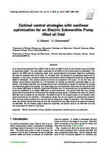
Figure 1 – LAN and WAN Architecture for METC Integrated Substations and Data Figure 1 shows the data communications architecture for substation protection, control, and data gathering. Here are some of the key design features: • Dual redundant and isolated optical fiber Ethernet LANs form the backbone of data communications for all protective relaying and substation or enterprise data gathering. • A router provides a gateway to a common carrier WAN. The WAN connects to a remote data hosting center, to METC primary and backup technical operations centers, and to other substations as needed. Enterprise clients for substation data access it through the data-hosting center, for robust cyber security architecture. • IEC 61850 GOOSE messaging combines with programmed logic in the relays to replace all of the prior-generation panel controls, indicators, meters, and lockout switches. There is minimal amount of control wiring among the relays and other IEDs in the station. • The design focuses on connecting each switchyard signal or control wire to only one relay or IED. That IED serves the status or analog value of that signal to all peer devices, and local or remote clients, over the LAN and/or WAN. All other relays, 5
•
•
•
•
•
•
•
• •
local operators, or remote operators control the connected power apparatus over the LAN. The LAN is based on managed Ethernet switches that isolate the dual redundant LAN segments. The Ethernet switches are treated as critical protective relaying components. They comply with IEEE Standard 1613 for physical and electromagnetic environment withstand capability, which in turn cites other IEC and IEEE environmental standards. The switch and fiber communications are configured so that no single failure disables protective relaying communications on either of the two redundant LANs. The switches operate directly from the 125 Vdc station batteries. Within each redundant LAN subsystem, multiple switches and primary/failover fiber connections to each relay allow each relay, fiber, or switch to be replaced without disrupting operation of that LAN segment. Multiple connections between switches on the dual redundant LANs allow control, polling, or GOOSE messages to pass from one redundant LAN to the other. A substation data concentrator gathers all periodic point status and value data from the relays, and transmits to the control center or to local substation clients. It receives and distributes local or remote control commands to the relays. It takes the place of a traditional RTU, but interfaces to the substation processes by talking to relays and IEDs on the LAN rather than having its own direct connections and transducers. The data concentrator also serves as a gateway for serial communicating IEDs including transformer gas and moisture analyzers, weather station sensors, and the physical security and substation physical access control systems. The concentrator communicates between the substation LAN data sources and regional control centers using legacy serial SCADA protocols that can readily change as a new control center is commissioned in 2007. A local Historian computer records the periodically gathered data values, and transmits them to a system Historian at the data-hosting center. The substation historian can bank operating history locally for weeks if communications to the data center is lost. In capturing the time sequence of all substation events and values, the Historian replaces the functionality of a sequence of events recorder (SER). However, it outperforms SERs because it records all the analog values and phasors along with the comprehensive list of event points. All relays and IEDs that generate data and status whose time of occurrence is important are synchronized to within 1 ms by a GPS receiver. For simple IEDs that don’t timestamp their values, such as weather sensors, the data concentrator provides a time stamp for the Historian. A specialized new fault and disturbance recording computer gathers oscillographic records, event logs, and data logs in COMTRADE (IEC 60255-24) format from the relays. It associates the multiple records, organizes them chronologically, and archives these records independently of the relays themselves, in a large flash memory. This solid-state recording computer replaces the functions of a digital fault recorder (DFR) or swing recorder, and does not require its own connections to substation signals. Servers in the remote data-hosting center acquire the fault and disturbance records from the substation DFR computer for enterprise use and long-term preservation. The User Interface computer displays a one-line diagram, and other local operator displays, for monitoring and control when an operator comes to the station. Backup for this control computer is programmed in the logic, pushbuttons, and indicating lights on the front panels of the microprocessor relays. 6
•
•
Digital video recorder system with array of video cameras monitors the periphery of the substation yard for intrusion detection, as well as providing a fairly high-resolution view of the power apparatus in the switchyard for remote monitoring and investigation of equipment problems. The complete base of substation operating data and event records are secured at the remote hosting center, and are available for the full range of enterprise users. Data base management and processing software running in data hosting center servers and at METC enterprise offices convert the mass of substation data to management tools and dashboards for operators, engineers, dispatchers, maintenance personnel, asset managers, and business managers.
Introducing IEC 61850 The introduction of IEC 61850 LAN communications is progressing for system integration as rapidly as is practical, to replace control wiring, and to simplify integration and data flow. IEC 61850 provides a unique high-speed LAN control multicast service called GOOSE messaging. Relays and IEDs that exchange GOOSE messages do not employ conventional control wiring on the panels. This has major and favorable impact on the panel design and cost. Furthermore, the LAN-based control readily grows and evolves to meet changing needs, substation expansion, or new functions without major field installation work or increased space. While all the relays have ability to serve data and control objects per the IEC 61850 Standard, clients’ functions will not be developed in time for the first substation installations. Therefore, periodic data gathering for these first upgraded substations is based on other widely used Ethernet-based protocols such as DNP3. This has no impact on the LAN or equipment design, or the ability of the system to use the LAN to eliminate conventional wiring and controls. Furthermore, this portion of the LAN data exchange can be readily transitioned to full IEC 61850 operations as client functions become available in the concentrators and in other remote clients for relay access. To the casual observer, there will be no difference. Despite widespread belief to the contrary, multiple Ethernet-based protocols can be combined on one LAN to achieve all the required functions. For METC, the transition to full use of IEC 61850 server-client object communications plus with 61850-based configuration tools will vastly simplify equipment and substation configuration, relay setting, and will dramatically reduce commissioning time. Relays provide self-descriptions for the clients and for substation configuration software tools, eliminating most of the familiar pointby-point SCADA, metering, and control configuration that is still required in the first upgrade installations. Protective Function Simplification Organizing protective functions using the newest generations of relays to improve dependability and security is another key component of the project, while drastically reducing the number of units required, and complying with or exceeding all agency design requirements. The first generations of microprocessor relays combined a panel full of relaying functions in one compact package, greatly reducing the panel space, wiring, and cost for protection of a zone. Today’s new generation of products include even more functions than before, and now support further panel and equipment reduction.
7
Notably, several vendors offer relays with full zone protection functions, plus breaker related functions to handle more than one breaker. Breaker functions include monitoring and control, breaker failure protection, reclosing, and synchronism/safe close checking. There are separated current inputs and measurements for the CTs from each of two breakers feeding the zone. This is needed for breaker-and-a–half or ring bus connections to a line or transformer zone. In legacy METC substations, breaker functions are on separate panels from the zone protection relays, with separate breaker-dedicated relays. This was done in part to keep local backup (breaker failure) protection redundant and separate from any of the multiple redundant protection zone relays that might initiate breaker failure timing. This approach is supported in NERC and regional design and planning standards.
Line NW Relay Panel 1
Line NE Relay Panel 1 Bkr B Relay
Line NW Relay Panel 2
Line NE Relay Panel 2
Line NW Relay Panel 3
Line NE Relay Panel 3 B
Bkr A Relay
Bkr E Relay
Bkr C Relay
D
E
Xfmr SW Relay Panel 1
C
A
Xfmr SW Relay Panel 2
Xfmr SW Relay Panel 3
Bkr D Relay
Line SE Relay Panel 1 Line SE Relay Panel 2 Line SE Relay Panel 3
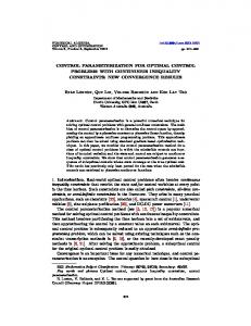
Figure 2 - Zone and breaker relays in the legacy system architecture See Figure 2. With the new relay types, the breaker functions and breaker local backup protection are absorbed into the line or other zone protection relays, eliminating the separate breaker panels. The breaker failure protection function is now liable to be lost if a line relay fails, which was not a threat in the older design. But if both of two redundant line relays each have full breaker failure backup protection, there is redundancy to handle any single equipment failure. This now yields a reliability and robustness improvement over the old design. Also, a shared connection point between the otherwise isolated redundant zone protection systems is removed. The most dramatic outcome from reorganizing the protection functions as shown in Figure 3 is that the number of protective relaying functional units drops from 17 to 8. This is due in part to the deployment of breaker functions in the zone relays as just explained, and in part by providing two fully duplicated redundant protection systems for each zone or breaker, rather than a larger array of partially redundant functions found on some legacy panels. Some of the legacy functional units comprised panels of discrete devices, while the new functional units 8
each comprise one 4 rack unit multifunctional relay. Accordingly, the panel and floor space drops by as much as 75%. Line NW Relay 1
Line NW Relay 2
Line NE Relay 1
Line NE Relay 2
Bkr A
Bkr A
Bkr B
Bkr B
Bkr B
Bkr B
Bkr C
Bkr C
B
C
A
D
E
Xfmr SW Relay 1
Xfmr SW Relay 2
Line SE Relay 1
Line SE Relay 2
Bkr D
Bkr D
Bkr C
Bkr C
Bkr A
Bkr E
Bkr A
Bkr D
Bkr D
Bkr E
Figure 3 - Zone and breaker relays in the new system architecture Operations & Maintenance One of the key objectives of the project was to implement technological improvements that would benefit long-term operations and maintenance. In particular, METC wanted to expedite situational awareness during system events and to minimize staff travel time. To achieve this, METC chose to install controllable video security cameras at each site. These cameras will be situated so as to perform dual functions. Each substation will have from 4 to 8 cameras installed. During the day some of them will be positioned to monitor the station equipment while the others will be used to scan the perimeter for intrusion detection. The cameras can pan and zoom based on local event triggers, or by remote control. This gives system operators quick visual context of the substation. The digital video stream from any camera can be captured for study by trigger from a power system or relaying event, as well as by security system detection. This includes several seconds of pre-trigger video, so that the events leading up to a trigger can be viewed. For these events, cameras will more precisely focus on the location of the activity. At night all cameras will be used for the perimeter security function. The cameras will also be used to perform periodic routine visual surveillance activities such as bushing oil level, further reducing the non-productive operator travel time between substations. Considering that METC covers approximately 33,000 square miles (85,000 square kilometers) this will yield sizable savings. The integrated communications network architecture and centralized information hosting will also reduce the need for operators to travel to substations to obtain trip targets, gather oscillography or event record files, or inspect status indications. All information will be available electronically to the Performance Engineers though reports and queries expediting 9
the root cause analysis of events. Also, management of the protective relay settings and firmware versions will in large part be performed through secured remote network access rather than by visiting technicians. These few examples highlight the significant benefits of robust communications architecture and the operational enhancements that are a by-product of the system. Minimalist Approach As explained later in this section, the relays and the protective functions within them have been carefully arranged to reduce the functional equipment units by more than half, and to eliminate multiple redundant connections between the protection and control system and the substation process. This new arrangement does a better job of meeting reliability criteria, including the requirement for no single point of failure that can disable protection in any zone. If mean time between failures were comparable, less than half the relaying units would mean that the newly designed substations will require less than half of the maintenance attention of the prior designs. There are two more factors that make the prospects even far better than this. We explained above that much of the equipment being replaced is quite old, beyond its intended design life, and calls for quite a bit of repair and calibration. The replacement equipment, along with being new and in the reliable portion of its life, is inherently free of need for calibration and attention beyond repair of failed units. The second factor that will vastly streamline the maintenance approach is that of properly utilizing the self-monitoring capabilities of the new relays and IEDs. Many users are aware that the new microprocessor-based devices are selfmonitoring, but just trusting the relay manufacturers and connecting alarm contacts is not an adequate strategy to reduce manual maintenance testing efforts. These points require focused attention to reduce invasive manual maintenance testing: • The designers look at exactly what hardware elements are monitored by each selftesting feature of each relay. The goal is to insure that every mission-critical hardware element is verified, and that elements on the boundary between subsystems are subjected to overlapping checks from both sides of the boundary. This includes any interconnecting wiring or communications among relays and the power apparatus, as well as hardware interfaces within the relay itself. If any important element should fail, an alarm must be sent to remote maintenance personnel at once. If protection is impacted, operating personnel may also need to be notified. • Of the components that cannot be functionally verified by a self-test, some can be exercised by METC operations as long as records are maintained regarding when and how the operation confirmation takes place. For example, consider a breaker trip circuit. Electrical continuity of the trip circuit and trip coil can be continuously monitored by new relays and failure is reported at once. However, this does not insure that the breaker can actually trip. If the line is subject to a number of faults per year, the multiple fault trip operations may be adequate to show breaker soundness and eliminate the need for other periodic testing. If a long time passes without a fault, it is then possible for operators to manually trip and close the breaker via SCADA through the LAN to each of the two redundant line or two redundant bus protection relays, verifying all the hardware in the tripping chains. To make this happen in practice, METC needs a database that tracks breaker operations, and flags breakers and relay trip paths needing operator test due to long periods of inactivity. • A few elements in the substation protective system may require periodic manual testing – the process that was once used on the entire protective relaying system. 10
•
•
However, there are very few such components and connections in the new design, and methods can be developed to eliminate even these few residual manual tests as experience accumulates. At the enterprise level, alarms for system operating problems and failure alarms must be tracked and fed into maintenance work planning systems. As just explained, the normal operations must be tracked for protection paths that cannot be self-monitored, so that operators and maintenance personnel get timely flags pointing to the need for remote SCADA operations to verify. Maintenance monitoring functions programmed at the data-hosting center and at the METC enterprise offices analyze the substation data stream, developing the action plans that are needed to remedy problems. Just as importantly, these enterprise applications create the monitoring and testing records that show that the protection and control system is healthy, for METC and its regulatory overseers. This is accomplished with a tiny fraction of the manual testing and verification needed in the past, and with reduced chance of error or neglect. On top of this, every utility has experience with relays that were damaged or left in an inoperable state after manual testing, and eliminating unnecessary human intervention reduces this risk. It is important to point out the critical maintenance benefit of the IEC 61850 GOOSE messaging service. If one relay has a rare need to trigger backup tripping of breakers connected to other relays (such as for a breaker failure), the sending relay is configured to send a multicast GOOSE message that can call for a backup trips and close blocking with 4 ms typical communications time over the LAN. All the relays that act on this trip and close-blocking command listen on the LAN for this particular message. As defined in 61850-8-1, the GOOSE messages are sent constantly and periodically - perhaps every second. Virtually all of the time, the message conveys negative or quiescent status –the backup tripping action is not to be carried out. However, all the relays that subscribe to the multicast message are constantly listening for this quiescent periodic GOOSE message on the LAN – if message streams are not received, the receiving relay raises an alarm. Thus, the system operators and maintenance personnel always know that the backup-tripping path is sound and able to perform if needed. If a sending or receiving relay fails or develops LAN communications problems, maintenance alarms are raised and the problem is fixed as soon as someone can get to the station. The ability of each relay to trip the breakers connected to it, based on microprocessor request, is separately verified by the process listed just above.
Note that there is no such monitoring possibility for a conventional breaker failure relay operating a lockout switch to trip and block other breakers – the operators cannot be sure that the backup tripping will work unless someone manually tests these tripping circuits. This test is so disruptive to an operating power system that it is rarely done. Data Warehousing and Information Access The newest relays and communications systems selected for the METC P&C upgrade present the enterprise with a massive stream of substation data that must be automatically stored, managed, analyzed, and presented in useful forms that improve business and technical operations. The data warehousing features of modern information architectures are essential to provide end users with easy access to the wealth of data and information substation devices provide. Three types of data are being created and stored for later retrieval as needed: • Sequence of events records
11
• •
High-speed time series data records such as COMTRADE oscillography and phasor measurement files. These records include binary status such as relay trip and close or unit line protection communications signals. Analog power system measurements and reports from equipment monitors such as transformer analysis IEDs.
All this data is collected organized and archived at the data-hosting center using the modeling standard CIM, and providing easy access by the staff. Today, CIM is embodied within IEC standards projects 61968 and 61970 [2, 3] and METC is benefiting from these standards through its use of readily available adapters that can be used to rapidly integrate data from various applications. Various diagnostic tools, including automatic preprocessing and dashboard reporting, are being developed to aid the end user in analyzing this wealth of information. In conjunction with the upgrade project is an integral effort to develop information systems for the METC staff. These systems will benefit Asset Management, System Planning and Operations. Information dashboards that support each of these business areas are currently under development. For example, operations will have ready access to fault location information, SER, lightning strikes, transformer monitors, weather and video streams and operating performance information. Planners will benefit with more accurate system and device loading information, better system event capture, weather profiles and improved system models. Asset Management will have access to an immense array of information that will be distilled from the detailed operating data. For example, consider transformer monitoring and life management. METC is installing gas-in-oil detectors. The transformer relays report currents and voltages. Top-oil temperature sensors and accessory alarms connect to data collection IEDs. A weather station reports ambient conditions. This body of data can support life assessment and emergency operating decisions. To get these results, the key data is extracted and analyzed with modeling algorithms and stored as trend results for each transformer. METC intends to use self-organizing neural networks to preprocess the vast amounts of operational data for the operating and maintenance management personnel who will get prioritized succinct information on which they can act, quickly if needed. Also, data or alarms indicating maintenance problems or repair issues can act as triggers. These can originate in the substation, or with back-office processing functions. These drive notices to business partners; create work orders and status tracking, map issues to GIS, update asset management records, and search for patterns or issues requiring broad action. Conclusions METC will make a significant investment in initial design and installation. The first step is to integrate three substations in a project that controls risk and demonstrates results. As more stations are upgraded, METC will reap the full benefits of the integrated substation control and protection architecture. The implementation described above includes: • Integrating all relaying, control, monitoring, automation, communications, and enterprise functions with Ethernet LANs in the substations. • Introducing IEC 61850 protocol as rapidly as is practical, to replace control wiring, and to simplify integration and data flow.
12
•
Organizing protective functions using the newest generations of relays to improve dependability and security, while drastically reducing the number of units required, and meeting agency design requirements. • Looking at recent operating issues, relaying problems, industry trends, and recent wide-area events; designing a solution that aims squarely at improving performance on these specifics. • METC has structured the implementation project so as to benefit its customers and staff through efficient transmission reliability. The strategy has been presented from an industry perspective, to give insights to a new and practical business approach for upgrading aging protection, control, and communications infrastructure. Many utilities in the US and around the world facing such a problem could benefit from a parallel approach, tailored to their particular circumstances. BIBLIOGRAPHY [1] IEC 61850, Communications Networks and Systems in Substations, 2005 [2] IEC 61968, System Interfaces for Distribution Management (draft sections in development, TC 57 WG 14) [3] IEC 61970, Energy Management System Application Program Interface (EMS-API) (draft sections in development, TC 57 WG 13) [4] North American Electric Reliability Council, Technical Analysis of the August 14, 2003 Blackout: What Happened, Why, and What Did We Learn? July 13, 2004
13