countries are typically thin and have a low concrete strength, web steel ratios that ... with RC walls, seismic demands in low-rise housing are low, thus leading to ...
Backbone Model for Performance-Based Seismic Design of RC Walls for Low-Rise Housing Julian Carrillo,a)
M.EERI,
and Sergio M. Alcocer,b)
M.EERI
The walls of modern low-rise economic housing in several Latin American countries are typically thin and have a low concrete strength, web steel ratios that are smaller than the minimum prescribed by current codes, and web shear reinforcement made of welded-wire mesh. In light of these particular wall characteristics, research was aimed at developing a performance-based backbone model capable of predicting the seismic behavior of reinforced concrete (RC) walls for one- and two-story housing. The selected tri-linear model is associated with three limit states: diagonal cracking, peak shear strength, and ultimate deformation capacity. The model was developed on the basis of the observed response of 39 quasi-static and shake table experiments. Iterative nonlinear regression analyses were performed for deriving the semi-empirical equations in this study. The paper also discusses the adequacy of some existing models to predict the seismic behavior of RC walls and the limitations of the proposed equations. [DOI: 10.1193/1.4000068]
INTRODUCTION Over the last ten years, in order to satisfy housing demand, the number of new housing units in several Latin American countries has increased considerably. A significant portion of these housing units are one to two stories high and have been constructed with reinforced concrete (RC) walls. Due to the lateral stiffness and strength of box-type structures made with RC walls, seismic demands in low-rise housing are low, thus leading to the use of thin walls (100 mm). Typically, concrete design strength varies between 15 MPa and 20 MPa. For these cases, the minimum wall reinforcement prescribed by the American Concrete Institute’s Building Code (ACI 2011)—0.25% for both vertical and horizontal reinforcement—appears to be excessive for controlling diagonal tension cracking. The use of thin walls, web reinforcement in ratios smaller than the minimum code-prescribed values, and web shear reinforcement made of welded-wire mesh are also the consequences of the hasty construction and cost-cutting practiced by developers in order to be competitive in the housing market. A large research program has been underway in the Instituto de Ingeniería at the Universidad Nacional Autónoma de México (UNAM) that is aimed at studying the seismic
a)
Research Professor, Department of Civil Engineering, Universidad Militar Nueva Granada, Colombia, Carrera 11 No. 101-80, Bogotá, Colombia b) Research Professor, Instituto de Ingeniería, Universidad Nacional Autónoma de México, Ciudad Universitaria, CP 04510, Mexico City, Mexico 943
Earthquake Spectra, Volume 28, No. 3, pages 943–964, August 2012; © 2012, Earthquake Engineering Research Institute
944
J. CARRILLO AND S. M. ALCOCER
behavior of lightly reinforced, thin concrete walls and developing guides for the analysis and design of low-rise housing. The experimental program comprised quasi-static tests (monotonic and reversed-cyclic) and dynamic loading tests of walls with different height-to-length ratios; walls with openings (door and window) were also tested. Carrillo and Alcocer (2012c) demonstrated that peak shear strengths calculated using most available models in the literature do not adequately correlate with those measured during testing of walls. This was particularly true of the type of RC walls found in the low-rise housing under study. Furthermore, the deformation response of some of these walls was also overestimated. Based on these findings, it was deemed necessary to develop a model in which low-rise housing characteristics were taken into account. A performance-based seismic design (PBSD) approach was considered so that suitable limit states could be taken into account. Then it was necessary to develop and calibrate a backbone response curve in order to apply the PBSD approach to typical RC housing. The following requirements were established for developing the model: (a) the model had to define the characteristic force-deformation relations from cracking to lateral load at failure, as a function of the relevant performance indicators, (b) the model had to include a nonlinear response because the structural system under study is expected to undergo nonlinear behavior in the event of a severe earthquake (Riahi et al. 2009). The main objective of this paper is to report on the development of a backbone model for typical RC walls with the following characteristics: a M∕Vlw ratio (the ratio between the bending moment and shear force times the wall length) varying between 0.5 and 2.0, prismatic walls (e.g., a consistent thickness along the wall length), concrete with a compressive strength varying between 15 MPa and 25 MPa, walls with axial stress ðσ v Þ less than 0.03 f c0 , and a web steel ratio smaller than or equal to 0.25% (this applies to both vertical and horizontal web reinforcement). Shake table and quasi-static test results from 39 RC walls were considered to develop the proposed model. Iterative nonlinear regression analyses were performed for deriving the semi-empirical equations in this study. The adequacy of the existing models in simulating the seismic behavior of RC walls was assessed through comparison with the proposed model. EXPERIMENTAL PROGRAM Most experimental studies on the seismic behavior of walls reported in the literature include wall specimens with characteristics different from those oftypical low-rise housingunits in Latin America, i.e., low concrete strength, thin walls, low axial stress, low steel ratios, and web shear reinforcement made of deformed bars or welded-wire mesh. Therefore, an experimental program comprising walls with these characteristics was implemented to verify the adequacy of the existing models for predicting the behavior of walls with the characteristics reported. In this program, 39 isolated walls were tested in cantilever. The walls were named using the following labeling system. Take, as an example, “MCN50mC”. The letter “M” indicates a wall test (from muro, in Spanish). The second letter indicates the height-to-length ratio ðhw ∕lw Þ: R ¼ hw ∕lw equal to 0.5, C ¼ hw ∕lw equal to 1.0, E ¼ hw ∕lw equal to 2.0, and V ¼ walls with openings (door and window). The full-scale wall thickness, tw , and clear height, hw , were 100 mm and 2.4 m, respectively. Then, to achieve the
BACKBONE MODEL FOR PERFORMANCE-BASED SEISMIC DESIGN OF RC WALLS FOR LOW-RISE HOUSING
945
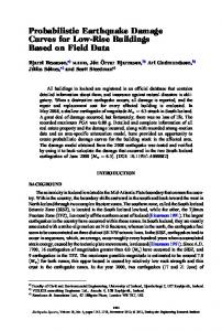
height-to-length ratio, the length of the walls was varied. The thickness of the boundary elements was equal to the thickness of the wall web. The third letter indicates the concrete type: N ¼ normal weight, L ¼ lightweight and S ¼ self-consolidating concrete. The nominal concrete compressive strength, f c0 , was 15 MPa. The fourth indicator relates to the web steel reinforcement ratio: 100 ¼ 100% of ρmin (0.25%), 50 ¼ 50% of ρmin (0.125%), and 0 ¼ 0% of ρmin , that is, walls without reinforcement. The latter walls were tested to have a reference value of the response of plain concrete walls. The minimum web steel ratio ðρmin Þ was that prescribed by the American Concrete Institute’s Building Code (ACI 2011), which is similar to that prescribed in the Mexico City’s Buildings Standards for Design and Construction of Concrete Structures (NTC-C 2004). Web reinforcement was placed in a single layer in the middle of the thickness of the walls; the same amount of horizontal and vertical reinforcement was used. The fifth indicator relates to the type of web reinforcement. When deformed bars were used, the letter is omitted. Otherwise, a lower-case letter “m” indicates that weldedwire mesh (made of small-gauge wires) was used. Finally, the last letter indicates the type of testing procedure. The letter “D” indicates that the wall underwent dynamic testing through shake table excitations. During shake table testing, the models were subjected to a series of base excitations from earthquake records associated with three limit states. Isolated models were designed considering the fundamental period of vibration of the prototype house. For establishing the period, analytical models were developed and calibrated through ambient vibration testing (Carrillo and Alcocer 2012a). A mass-carrying load system for supporting the mass and transmitting the inertia forces was designed. The device was allowed to slide horizontally on a fixed supporting structure located outside the shake table (Figure 1a). Detailed characteristics and an explanation of the advantages of the device may be found in Carrillo and Alcocer (2011).
Figure 1. Test setups: (a) shake table testing, (b) quasi-static testing.
946
J. CARRILLO AND S. M. ALCOCER
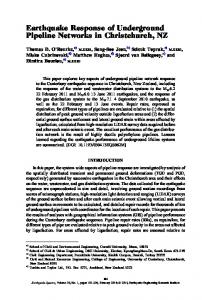
Figure 2. Typical geometry and reinforcement layout of wall specimens: (a) hw ∕lw ¼ 1.0, 100% of ρmin and using deformed bars; (b) wall with openings, 50% of ρmin and welded-wire mesh.
The letters “M” and “C” indicate quasi-static testing with a monotonically or cyclically increased load, respectively. In quasi-static reversed-cyclic testing, the loading protocol consisted of a series of increasing amplitude cycles. For each increment, two cycles at the same amplitude were applied. Before attaining the actual cracking load, the cycles were controlled by force. After cracking, the loading history was controlled by the drift ratio. Lateral loads were applied directly at the top slab level through double-action hydraulic actuators, as shown in Figure 1b. An axial compressive stress of 0.25 MPa was applied at the top of the walls and was kept constant during testing. This value corresponded to an average axial stress in the first floor walls of a two-story prototype house. The axial load corresponded roughly to 2% of the nominal concrete compressive strength. The typical geometry and reinforcement layout of some of the full-scale wall specimens is shown in Figure 2. Ranges of the mechanical properties of the concrete in the 39 specimens are presented in Table 1. These properties were measured at the time of testing. The nominal yield strength of the bars and wire reinforcement, f y , was 412 MPa (for mild steel) and 491 MPa (for cold-drawn wires), respectively. Ranges of the measured mechanical properties of the steel reinforcement in the 39 specimens are presented in Table 2. The typical Table 1.
Measured mechanical properties of concrete
Type Compressive strength, f c , MPa Elastic modulus, Ec , MPa Tensile splitting strength, f t , MPa Flexural strength, f r , MPa Specific dry weight, γ, kN/m3
Normal weight, N
Lightweight, L
Self-consolidating, S
16.0–24.7 8430–14750 1.55–2.20 2.32–3.75 18.8–20.3
10.8–26.0 6700–10790 1.14–1.76 1.43–3.29 15.2–18.3
22.0–27.1 8900–11780 1.58–1.98 2.27–2.48 18.9
BACKBONE MODEL FOR PERFORMANCE-BASED SEISMIC DESIGN OF RC WALLS FOR LOW-RISE HOUSING
Table 2.
947
Measured mechanical properties of steel reinforcement
Location in the wall Type Yield strength, f y , MPa Ultimate strength, f su , MPa Elongation, %
Boundary: deformed bar Web: deformed bar, D Web: welded-wire, W Mild 411–456 656–721 9.1–16.0
Mild 435–447 659–672 10.1–11.0
Cold-drawn 605–630 687–700 1.4–1.9
stress-strain behavior of the web steel reinforcement measured using coupon tests is shown in Figure 3. The fitted stress-strain curve for the two types of web shear reinforcement is included in the figure. In the cold-drawn wire reinforcement used in this study, the elongation capacity (at fracture) was much shorter than that of mild-steel reinforcement. The behavior of wire reinforcement was characterized by fracture of the material with a slight increment of strain. Because of their aspect ratio, the behavior of the RC walls tested was expected to be controlled by shear deformations, therefore they were likely to exhibit a brittle failure mode governed by shear demands. Since the aim of this program was to study the shear behavior of the walls, the longitudinal boundary reinforcement used was purposely designed and detailed to prevent a flexural failure prior to achieving a shear failure. The main characteristics of the 39 wall specimens are presented in Table 3. For evaluating the observed wall behavior, three failure modes were defined: (a) when most of the web shear reinforcement yielded but there was no crushing of the web concrete, a diagonal tension failure (DT) occurred; (b) when some of the steel bars or wires yielded and noticeable crushing and spalling of the web concrete was observed, a diagonal compression failure (DC) was recorded; and (c) when the majority of the web steel reinforcement yielded and noticeable crushing of the web concrete was observed, a mixed failure mode (DT-DC) was established.
Figure 3. Typical stress-strain curves of web steel reinforcement: Deformed bars (D) and wires of welded-wire mesh (W).
948
Table 3.
J. CARRILLO AND S. M. ALCOCER
Main characteristics of wall specimens
Type of testing
Wall
Type of f c , Type of web f y , ρh ¼ ρv , t w , hw , concrete MPa reinforcement MPa % mm mm
lw , mm hw ∕lw
N N N L L L S S
18.8 18.8 18.8 16.3 16.3 16.3 19.4 19.4
— D D — D D — D
— 447 447 — 447 447 — 447
0 0.14 0.28 0 0.14 0.28 0 0.28
101 102 101 101 102 101 102 102
2412 2415 2417 2428 2427 2425 2425 2424
2403 2402 2402 2398 2397 2398 2398 2397
1.00 1.01 1.01 1.01 1.01 1.01 1.01 1.01
Quasi-static: MCN50C reversed-cyclic MCN100C MCS50C* MCS100C MCL50C* MCL100C MRN100C MEN100C MRN50C MEN50C MRL100C MRN50mC MCN50mC MEN50mC MRL50mC MCL50mC MEL50mC MVN100C MVN50mC MCN50C-2 MCS50C-2 MCL50C-2 MCL100C-2 MCNB50mC MRNB50mC
N N S S L L N N N N L N N N L L L N N N S L L N N
17.5 17.5 22.0 22.0 10.8 10.8 16.2 16.2 16.2 16.2 5.2 20.0 20.0 20.0 5.2 26.0 26.0 16.0 16.0 20.0 27.1 26.0 5.2 8.9 8.9
D D D D D D D D D D D W W W W W W D W D D D D W W
447 447 447 447 447 447 447 447 447 447 447 605 605 605 605 605 605 447 605 447 447 447 447 605 605
0.14 0.28 0.14 0.28 0.14 0.28 0.28 0.28 0.14 0.14 0.28 0.12 0.12 0.12 0.12 0.12 0.12 0.26 0.11 0.14 0.14 0.14 0.29 0.12 0.13
102 101 102 103 101 101 100 100 100 100 101 103 103 101 106 100 100 110 110 100 104 100 98 102 100
2431 2432 2424 2426 2426 2424 2433 2435 2425 2421 2423 2401 2396 2399 2419 2423 2435 2397 2397 2400 2404 2426 2432 2404 2401
2399 2397 2403 2401 2398 2399 2400 1240 2400 1240 5413 5396 2398 1239 5415 2403 1221 3826 3826 2398 2402 2441 2407 2401 5400
1.01 1.01 1.01 1.01 1.01 1.01 0.45 1.96 0.45 1.95 0.45 0.44 1.00 1.94 0.45 1.01 1.99
Dynamic: shake table
N N L L N N
24.7 24.7 21.0 21.0 24.7 24.7
W D W D W D
630 435 630 435 630 435
0.11 0.26 0.11 0.27 0.11 0.26
83 84 82 82 83 84
1923 1924 1917 1918 1924 1926
1916 1921 1917 1912 3042 3042
Quasi-static: monotonic
MCN0M MCN50M MCN100M MCL0M MCL50M MCL100M MCS0M MCS100M
MCN50mD MCN100D MCL50mD MCL100D MVN50mD MVN100D
** **
1.00 1.00 0.99 1.01 1.00 0.44 1.00 1.00 1.00 1.00 ** **
D = deformed bar, W = welded-wire mesh, * = maximum displacement capacity was not attained, ** = wall with openings.
BACKBONE MODEL FOR PERFORMANCE-BASED SEISMIC DESIGN OF RC WALLS FOR LOW-RISE HOUSING
949
Wall sliding at the base was purposely not included in this study; none of specimens tested exhibited failure or significant distress associated with sliding. PROPOSED MODEL Most seismic codes, including the American Concrete Institute’s ACI-318 (ACI 2011) and Mexico City’s Building Standards for Design and Construction of Concrete Structures (NTC-C 2004), rely mainly on conventional force-based limit states (i.e., ultimate limit state) and on a serviceability limit state, but they do not include an explicit relationship between displacement demand and capacity. In contrast, modern design procedures place more emphasis on the deformation capacity of a system. For example, PBSD requires the explicit consideration of lateral displacement as a performance indicator, besides verifying the structural design through an essentially force-based procedure (Priestley 2000). PBSD has been applied to systems failing under flexural mode, but its implementation for systems under shear failure is still limited. According to a literature review (Carrillo and Alcocer 2012c), to date there is no methodology for performance-based design of RC walls failing in shear. One of the main obstacles hindering the implementation of PBSD in these cases is the absence of suitable models for predicting the load-displacement curve of elements failing in shear. Several analytical models have been proposed for predicting peak shear strength (Barda et al. 1977, Hernández and Zermeño 1980, Wood 1990, Leiva and Montaño 2001, Flores et al. 2007, ACI 2011, Gulec and Whittaker 2009) and the load-displacement curve of RC walls (Benjamin and Williams 1957, Hidalgo and Jordán 1996, Habasaki et al. 2000, FEMA 2000, Gérin and Adebar 2004, Tu et al. 2006, Wallace 2007, ASCE 2007, Sánchez 2010). Nevertheless, due to the particularities of the RC walls in low-rise housing, most of the design recommendations and equations in the existing models are not directly applicable. In general, the main limitations are: (i) previous models have been developed on the basis of a much wider range of parameters controlling the shear behavior of walls; in contrast, in typical lowrise housing, the parameters vary in a narrower range (low concrete strength, thin walls, low axial stress, low steel ratios); (ii) the behavior of walls with web shear reinforcement made of welded-wire mesh is not explicitly included in previous models; in the walls tested in this study, the low strain capacity (elongation) of the cold-drawn wire reinforcement, which significantly reduces the displacement capacity of walls, is a key parameter for PBSD; (iii) previous models have been calibrated on the basis of results observed from quasi-static tests only, that is, loading rate effects, low-cycle fatigue, cumulative parameters (Carrillo and Alcocer 2012b), and the dynamic effect of the vertical axial stress on the wall shear strength have been excluded and finally, (iv) some previous models are not readily practical and versatile for low-rise housing design purposes. MODEL CHARACTERISTICS
Limit States Design for seismic resistance has been undergoing a critical reappraisal in recent years, switching the design emphasis from “strength” toward “performance,” and in many cases to “displacement.” One of the major developments in seismic design over the past 20 years has been the increased importance placed on limit states design, now generally termed performance-based engineering (Priestley 2000). In these modern design procedures, it is essential
950
J. CARRILLO AND S. M. ALCOCER
Figure 4. Proposed backbone model.
to explicitly identify the stiffness, strength, and displacement capacity of structural elements, as well as of the system as a whole. Analyzing the shape of the experimental hysteresis curves, it was decided that a tri-linear backbone model was suitable for describing the performance of walls in low-rise housing. The proposed backbone model for PBSD is shown in Figure 4. The tri-linear model is described using parameters associated with the three limit states: diagonal shear cracking ðV cr ; Δcr Þ, peak shear strength ðV max ; Δmax Þ, and ultimate deformation capacity ðV u ; Δu Þ. The diagonal shear cracking limit state is reached when the initial inclined web cracking is observed. When the peak shear strength is attained, the strength limit state is reached. The ultimate deformation capacity limit state is associated with one of the two following scenarios: when a 20% drop in peak shear strength is observed or when the web shear reinforcement is fractured. In the specimens studied the first scenario occurred in walls reinforced with deformed bars; the second scenario was observed in walls with web shear reinforcement made of welded-wire mesh. In the proposed model, the initial branch ended when the first inclined web crack, caused by diagonal tension forces, was observed. In this first branch, loss of stiffness due to shear and flexural cracking, typically observed at the beginning of wall loading, was included. At the end of the second branch (i.e., at strength), cracking caused by diagonal tension was assumed to penetrate both the top and bottom edges of the boundary elements. Finally, in the unloading branch, a loss of strength and stiffness, caused by web crushing and/or yielding and fracture of the web reinforcement, was observed and thus led to a shear failure of the wall. Model Development To develop the backbone model, parameters (variables that characterize limit states) associated with specific performance levels were identified and measured. The analytical models available in the literature, the results of previous studies, test observations, and the fundamentals of RC structural behavior were all used in selecting the most representative variables and setting the functional form of the model equations. In addition, recommendations
BACKBONE MODEL FOR PERFORMANCE-BASED SEISMIC DESIGN OF RC WALLS FOR LOW-RISE HOUSING
951
prescribed by the American Concrete Institute (ACI 2011) and Mexico City (NTC-C 2004) design codes were also considered. Regression analyses, the trends of residuals (prediction errors), and design variables helped to improve the form of the equations. SHEAR STRENGTH CAPACITY
Peak Shear Strength, V max Equation 1, which is similar those in many current design methodologies, is proposed for estimating the peak shear strength of the RC walls used in typical low-rise housing. The equation was proposed by Carrillo and Alcocer (2012c) and was calibrated using the 39 isolated walls described in the experimental program (Table 3). Equation 1 assumes that shear strength is made up by the contribution of the concrete, V c , plus that of the web steel reinforcement, V s . � � pffiffiffiffi pffiffiffiffi 0 V max ¼ V c þ V s ¼ α1 f c þ ηh ρh f yh Aw ≤ α2 f c0 Aw (1) EQ-TARGET;temp:intralink-;e1;62;482
where α1 and α2 are coefficients defining the relative contribution of the concrete to diagonal tension and diagonal compression strength, respectively. Such contributions are calculated using Equations 2 and 3, respectively. � � M ðMPaÞ (2) α1 ¼ 0.21 − 0.02 Vlw EQ-TARGET;temp:intralink-;e2;62;413
α2 ¼ 0.40 ðMPaÞ EQ-TARGET;temp:intralink-;e3;62;383
(3)
where M∕Vlw is the ratio between the bending moment and shear force times wall length. In Equation 1, f c0 is the specified concrete compressive strength, ρh is the horizontal web steel ratio, ηh represents the efficiency of ρh and should be calculated using Equation 4, and f yh is the yield strength of the horizontal web shear reinforcement. Equation 1 was calibrated on the basis of the gross area of a concrete wall section, Aw , that is, wall thickness ðtw Þ times wall length ðlw Þ. ηh ¼ 0.8 For deformed bars (4a) EQ-TARGET;temp:intralink-;e4a;62;285
EQ-TARGET;temp:intralink-;e4b;62;263
ηh ¼ 0.7 For welded-wire mesh
(4b)
Diagonal Cracking Shear Strength, V cr Benjamin and Williams (1957) stated that the shear force associated with the development of the first inclined web crack is completely dependent on web reinforcement (steel ratio, type of reinforcement, and bar/wire location). Benjamin and Williams (1957) concluded that the first change in the slope of the load-displacement curve may be noted when distributed diagonal web cracking occurs, and this conclusion proved to be true during the tests reported here. Distributed diagonal web cracking is commonly exhibited at a load larger than that associated with the first inclined web crack. Shear strength at distributed diagonal web cracking corresponds essentially to the shear force at which the principal tension stress of the concrete is reached. Thus, in the proposed model, it is assumed that V cr is similar to contribution of the concrete to the shear strength,
952
J. CARRILLO AND S. M. ALCOCER
then: V cr ¼ V c ¼ α1
EQ-TARGET;temp:intralink-;e5;41;627
pffiffiffiffi f c0 Aw
(5)
Ultimate Shear Strength, V u As in the current methodologies (Hidalgo and Jordán 1996, Sánchez 2010), in this study the ultimate deformation capacity limit state is associated with a 20% drop in the peak strength, or the fracture of web shear reinforcement made of welded-wire mesh. For the former case: V u ¼ 0.8V max
EQ-TARGET;temp:intralink-;e6;41;535
(6)
DISPLACEMENT CAPACITY
The equations presented in this paper were developed in terms of drift ratio (as a percentage), as it is a very common performance indicator used in design. Drift ratio, R, was obtained by dividing the relative displacement measured at mid-thickness at the top of the slab by the height at which the displacement was measured ðH w Þ. The proposed relationships are based on a model in which the total displacement is calculated as the sum of contributions related to flexure and shear. The contribution of wall sliding at the base was omitted because the sliding displacements measured during the tests were minimal (Carrillo and Alcocer 2012a). Diagonal Cracking Drift Capacity, Rcr On the basis of observed trends from experimental results, and considering the findings of similar studies (Benjamin and Williams 1957, Hidalgo and Jordán 1996, Habasaki et al. 2000, Hidalgo et al. 2002, Gérin and Adebar 2004, Wallace 2007, Sánchez 2010), it was assumed that the displacement associated with diagonal cracking was independent of the ratio and type of web steel reinforcement. Thus, using the diagonal cracking shear strength ðV cr Þ, calculated via Equation 5, and the cracked initial stiffness ðK cr Þ, Equation 7 is proposed for calculating Rcr . � � V cr 100 Rcr ð%Þ ¼ (7) K cr H w EQ-TARGET;temp:intralink-;e7;41;281
where K cr includes both shear and flexural deformations. According to Ghobarah (2004), realistic drift calculations should be made using a reduced gross inertia due to the properties of the cracking section. Aristizabal-Ochoa (1983) stated that nonlinearity occurs at load levels lower than those associated with the onset of yielding in reinforcement, and thus it is sufficient to reduce the values of initial elastic stiffness, particularly for lightly reinforced concrete walls. For walls tested in cantilever, K cr is calculated from conventional theory of materials using Equation 8. �−1 � h3w hw K cr ¼ þ (8) c1 3E c I g c2 Gc Ac EQ-TARGET;temp:intralink-;e8;41;154
where Ac is the shear area of the wall cross section ðAw ∕1.2Þ, E c is the modulus of elasticity of the concrete, I g is the moment of inertia of the gross concrete section about the centroidal axis, Gc is the shear modulus of the concrete, and c1 and c2 are factors for including cracking
BACKBONE MODEL FOR PERFORMANCE-BASED SEISMIC DESIGN OF RC WALLS FOR LOW-RISE HOUSING
953
of the concrete prior to the reinforcement yielding. Factors c1 and c2 were estimated by means of the ratio between observed initial stiffness and initial stiffness calculated using finite element models and the measured mechanical properties of the materials ðK obs ∕K cal Þ. Observed initial stiffness was calculated using results measured during shake table testing; initial stiffness was associated with a drift ratio equal to 0.02%. Although the mean value of factors c1 and c2 were equal to roughly 0.56, Carrillo and Alcocer (2012a) have recommended the use of c1 ¼ c2 ¼ 0.5 for the practical seismic design of walls used in typical low-rise housing. Drift Capacity at Peak Shear Strength, Rmax To evaluate the trends from the experimental results, curves showing the relationship pffiffiffiffi between measured drift capacity at peak shear strength ðRmax Þ and the ðυmax ∕ f c0 Þ lw ratio were constructed. The failure modes, as well as the measured shear strength and drift capacities of the 39 wall specimens are summarized in Table 4. Drift at strength, Rmax , was directly obtained from the measured hysteresis curves that were expressed pffiffiffiffi in terms of shear force and lateral drift ratio. During calculation of the ratio ðυmax ∕ f c0 Þ lw , υmax was computed as the ratio between the peak shear force ðV max Þ and the gross area of the wall bounded by measured wall thickness and wall length ðAw ¼ t w × lw Þ, where f c0 corresponds to the compressive strength of the concrete measured at the time of testing. The results were divided according to the M∕Vlw ratio and type of web reinforcement (deformed pffiffiffiffi bars and welded-wire mesh). The relationship between Rmax and the ðυmax ∕ f c0 Þ lw ratio is shown in Figure 5. Only walls failing in diagonal tension (DT) or in a mixed failure mode (DT-DC) were included. To reflect the behavior of walls under cyclic loading only, experimental data was taken from the series of shake table and quasi-static reversed-cyclic tests. Walls with openings were not included as they are not associated with a unique M∕Vlw ratio. Two of the walls tested are not included in the table because their displacement capacity was not exhausted; they were rehabilitated and retested (Table 3). pffiffiffiffi As shown in Figure 5, the relationship between Rmax and the ðυmax ∕ f c0 Þ lw ratio depends on the M∕Vlw ratio and the type of web reinforcement. Therefore, drift capacity at peak shear strength also depends on the failure mode of the wall. As in other studies (Duffey et al. 1994, Hidalgo et al. 2002), it was observed that as the M∕Vlw ratio decreased, the displacement capacity at peak shear strength also decreased. This occurs because the lateral stiffness of the wall increases and the failure mode becomes more brittle. Equation 9 is proposed for estimating Rmax . This equation was derived from observed trends and nonlinear regression analyses. Constants a1 , a2 , b1 , and b2 depend on the type of web shear reinforcement. The proposed values for these constants are presented in Table 5. Rmax ð%Þ ¼
EQ-TARGET;temp:intralink-;e9a;62;204
EQ-TARGET;temp:intralink-;e9b;62;157
V max 1 b1 ðM∕Vlw Þ pffiffiffiffi e For deformed bars t w f c0 a1
� � V max 1 M b2 Rmax ð%Þ ¼ pffiffiffiffi0 For welded-wire mesh tw f c a2 Vlw
(9a)
(9b)
As can be readily observed in Equation 9, drift capacity at peak shear strength depends on web steel ratio (horizontal and vertical), wall geometry, wall boundary conditions, and
234 274 240 250 184 226
MCN50mD DT MCN100D DT-DC MCL50mD DT MCL100D DT-DC MVN50mD DT MVN100D DT-DC
0.44 0.53 0.62 0.50 0.40 0.49
0.66 0.81 1.01 0.81 1.40 0.69 1.16 0.39 0.47 0.66 0.44 0.60 0.70 0.67 0.40 0.44 0.39 0.57 0.80 0.40
Rmax , %
0.54 0.58 0.65 0.73 0.44 0.82
1.02 1.34 1.49 0.99 1.80 1.01 2.07 0.45 0.52 0.68 0.45 0.63 0.71 1.09 0.40 0.72 0.59 1.18 1.51 0.67
Ru , %
1.00 17.4 26.9
1.15 1.26 0.84 1.41 0.91 0.73
0.84 0.93 0.71 0.93 0.94 0.90 0.84 0.90 1.16 1.16 1.04 0.87 1.04 0.91 1.02 1.25 1.30 0.91 0.94 1.03
This study
1.21 28.6 58.3
1.66 1.39 1.17 1.47 1.38 1.66
0.99 0.81 0.65 + 0.78 0.57 0.94 1.02 1.39 1.66 0.89 1.09 1.57 1.01 1.71 1.50 1.67 1.13 + 0.98
Hidalgo & Jordán
+ = failure mode is not included in the analytical model.
Mean Coefficient of variation, CV (%) Over-predictions, Op (%)
352 453 475 336 208 670 157 776 329 154 568 400 172 383 252 329 321 375 336 612
DT DC-DT DT-DC DC DC-DT DT DT DT DT DT DT DT DT DT-DC DT DT DT DT DC DT
MCN50C MCN100C MCS100C MCL100C MEN100C MRN50C MEN50C MRN50mC MCN50mC MEN50mC MRL50mC MCL50mC MEL50mC MVN100C MVN50mC MCN50C-2 MCS50C-2 MCL50C-2 MCL100C-2 MRNB50mC
V max , kN
Failure mode
0.95 26.2 45.8
1.19 0.96 0.84 1.01 1.08 1.25
0.76 0.59 0.48 + 0.47 0.71 0.61 1.33 1.08 1.09 1.01 0.86 1.10 0.72 1.18 1.14 1.31 0.89 + 1.14
Habasaki et al.
0.48 48.1 0.0
0.38 0.42 0.42 0.70 0.94 0.81
0.34 0.39 0.31 0.44 0.50 0.11 0.40 0.20 0.42 0.74 0.19 0.35 0.73 0.79 0.96 0.45 0.47 0.35 0.40 0.17
FEMA & ASCE
Rmax , %
Shear strength and drift capacity of wall specimens
Wall
Table 4.
1.08 26.8 61.5
1.50 1.15 1.11 1.29 1.12 1.37
0.93 0.80 0.64 0.82 0.54 0.81 0.61 1.49 1.31 1.10 1.28 1.04 1.09 0.82 1.25 1.37 1.55 1.07 0.67 1.39
Gérin & Adebar
0.67 30.7 0.00
0.91 0.76 0.64 0.80 0.58 0.70
0.61 0.49 0.40 0.50 0.29 0.58 0.34 1.04 0.85 0.61 0.91 0.67 0.57 0.43 0.73 0.92 1.02 0.70 0.50 1.00
Wallace
1.26 25.6 61.5
1.53 1.53 1.12 1.70 1.40 1.38
0.88 0.92 0.69 1.00 0.93 0.89 0.90 1.61 1.27 1.61 1.81 0.96 1.47 1.10 1.54 1.30 1.37 0.95 1.02 0.81
Sánchez
0.95 26.6 26.9
0.94 1.73 0.81 1.45 0.83 0.67
0.81 0.83 0.72 1.13 1.15 0.89 0.74 0.77 1.04 1.13 1.02 0.82 1.04 0.86 1.00 1.12 1.28 0.66 0.74 0.62
This study
Predicted / Observed ðP∕OÞ
1.59 42.1 79.2
1.34 3.36 1.12 2.66 2.34 1.52
1.64 1.24 1.12 + 1.79 0.74 1.56 0.88 1.25 1.62 0.88 1.03 1.57 1.77 1.68 2.31 2.81 1.39 + 0.59
Hidalgo & Jordán
0.63 49.8 7.7
0.31 1.30 0.40 1.03 0.91 0.74
0.74 0.56 0.50 0.76 0.42 0.75 0.36 0.17 0.38 0.72 0.18 0.33 0.73 0.69 0.94 1.04 1.27 0.64 0.50 0.10
FEMA & ASCE
1.34 41.9 76.9
1.22 2.66 1.06 2.13 1.52 1.25
1.58 1.08 1.08 1.07 0.89 1.48 0.84 1.28 1.18 1.07 1.26 0.99 1.09 1.04 1.23 2.24 2.91 1.46 0.36 0.83
Gérin & Adebar
Ru , %
0.88 38.0 19.2
0.74 1.73 0.61 1.37 1.22 0.64
0.98 0.74 0.67 1.01 0.56 0.99 0.48 0.89 0.77 0.59 0.89 0.63 0.57 0.92 0.72 1.38 1.69 0.85 0.66 0.60
Wallace
1.33 32.1 73.1
1.24 2.52 1.07 2.05 1.96 1.26
1.04 0.86 0.75 1.24 1.50 0.75 1.16 1.38 1.14 1.57 0.79 0.91 1.47 1.45 1.52 1.45 1.70 0.86 0.81 1.08
Sánchez
954 J. CARRILLO AND S. M. ALCOCER
BACKBONE MODEL FOR PERFORMANCE-BASED SEISMIC DESIGN OF RC WALLS FOR LOW-RISE HOUSING
955
Figure 5. Drift capacity at peak shear strength.
vertical axial stress. As mentioned earlier, for practical purposes, Rmax includes total wall deformations, i.e., both shear and flexural deformations. It is apparent from Figure 5 that experimental trends for walls with web reinforcement made of welded-wire mesh are noticeably different from walls with reinforcement made of deformed bars. This difference may be attributed to the distinct failure modes observed. In effect, in walls reinforced with weldedwire mesh, a diagonal tension failure mode, characterized by plastic yielding of the reinforcement and the subsequent fracture of the wires, was always observed in the tests. In contrast, walls reinforced with deformed bars included three failure modes (DT, DC, and mixed DT-DC). Therefore, the scatter in Rmax was higher for these walls. When including three failure modes in the equation needed for calculating the drift capacity of walls reinforced with deformed bars, an exponential model should be also used. For academic purposes it is possible to develop a set of three equations for walls reinforced with deformed bars, by taking into account the particular failure mode. However, it was decided that a more robust set of equations was not useful within a practical PBSD methodology. Ultimate Drift Capacity, Ru Duffey et al. (1994) have pointed out that care must be exercised in using drift values beyond peak load (i.e., in the strength decay branch), because relatively little resistive energy may remain in the structure, whereas the remaining energy in the earthquake may still be significant. As mentioned earlier, walls with web shear reinforcement made of welded-wire mesh exhibited an ultimate deformation capacity limit state that is associated with a peak shear drop of less than 20%. In these walls, the inelastic portion is almost nonexistent because of the limited elongation capacity of the cold-drawn reinforcement used in this type of houses (Table 2). It is expected that the nonlinear behavior would improve if the elongation capacity Table 5.
Constants for calculating drift capacity At peak shear strength, Rmax
Ultimate, Ru
Deformed bars (MPa)
Welded-wire mesh (MPa)
Deformed bars (MPa)
a1 ¼ 5200 b1 ¼ 1.30
a2 ¼ 1450 b2 ¼ 1.60
c1 ¼ 3650 d1 ¼ 1.35
956
J. CARRILLO AND S. M. ALCOCER
Figure 6. Ultimate drift capacity.
of the welded-wire mesh were increased. The ratio between the ultimate drift capacity measured and the drift capacity measured at peak shear strength ðRu ∕Rmax Þ for walls reinforced with deformed bars and with welded-wire mesh is shown in Figure 6a. The drift capacities measured are shown in Table 4. Like Rmax , Ru was directly obtained from the measured hysteresis curves that were, in turn, expressed in terms of shear force and lateral drift ratio. As shown in Figure 6a, for the walls with welded-wire mesh, mean Ru ∕Rmax was equal to 1.09, that is, the ultimate displacement capacity was almost equal to the displacement capacity at peak shear strength. In contrast, for walls with deformed bars, the value of Ru ∕Rmax varied between 1.2 and 2.2. Following the same procedure as for Rmax , Ru for the walls with deformed bars may be estimated from Equation 10a (Figure 6b). An iterative nonlinear regression analysis was used for calculating the constants c1 and d 1 (Table 5). Because of the brittleness of the failure mode observed in walls reinforced with welded-wire mesh, Ru was considered to be equal to Rmax (Equation 10a). Like Rmax , Ru includes the contributions of both shear and flexural deformations. Ru ð%Þ ¼
EQ-TARGET;temp:intralink-;e10a;41;290
EQ-TARGET;temp:intralink-;e10b;41;241
V max 1 d1 ðM∕Vlw Þ pffiffiffiffi e t w f c0 c1
Ru ð%Þ ¼ Rmax ð%Þ
For deformed bars
(10a)
For welded-wire mesh
(10b)
EVALUATION OF PROPOSED BACKBONE CURVE In order to evaluate the robustness of the available and proposed models for estimating the load-displacement behavior of the RC walls in typical low-rise housing, a statistical analysis and a comparison between the predicted backbone curve and measured hysteresis curves were performed. The statistical analysis was conducted using an assessment parameter defined as the ratio between the predicted and observed response parameters ðP∕OÞ. In all cases, as-built wall dimensions and measured mechanical properties of materials were used to calculate “predicted” shear strength and “predicted” displacement capacity. Predicted peak shear strength was associated with the failure mode
BACKBONE MODEL FOR PERFORMANCE-BASED SEISMIC DESIGN OF RC WALLS FOR LOW-RISE HOUSING
957
observed during testing. For walls where a mixed failure mode was observed, predicted peak shear strength corresponded to the lowest value of the predicted peak shear strengths associated with the two failure modes.
STATISTICAL ANALYSIS
Equation 1 has been found to adequately predict the peak shear strength of the RC walls in low-rise housing (Carrillo and Alcocer 2012c). Thus, assessment of the model’s parameters was carried out only in terms of displacement capacities (Rmax and Ru ). The main equations for the six existing analytical models used for comparison are presented in Table 6. The equations proposed by Hidalgo and Jordán (1996), FEMA (2000), ASCE (2007), Wallace (2007), and Sánchez (2010) include both shear and flexural deformations ðf þ sÞ. In contrast, the contribution of flexural deformations in the models proposed by Habasaki et al. (2000) and Gérin and Adebar (2004) should be calculated by means of a moment-curvature analysis of the wall cross section. Details of these models may be found in papers and reports indicated in the reference section. The observed parameters corresponded to the peak shear forces measured during shake table and quasi-static reversedcyclic testing. In the statistical analysis of P∕O ratios, mean, standard deviation ðSÞ, coefficient of variation ðCVÞ, extreme values, and over-predictions ðOpÞ were calculated. Over-predictions were computed as the ratio (as a percentage) between the number of data points where the P∕O ratio was higher than 1.05 and the total number of data points. A spare equal to 5% (1.05) was included for calculating Op. Results for the P∕O ratios are presented in Table 4. Modified box and whisker charts were used to facilitate the statistical analysis (Figure 7). The charts show the mean (solid circle), variation in terms of the standard deviation (the total height of the square represents two times S) and the extreme values (short horizontal line). The results for over-predictions are also included in the charts. When a P∕O ratio is lower than 1.0, the prediction is conservative. In contrast, if a P∕O ratio is higher than 1.0, the model equation overestimates the displacement capacity, and thus the prediction would be unconservative. To qualify the accuracy of the models used for predicting displacement capacities, robustness characteristics of the model were established. First, the mean value for the P∕O ratio should be equal to 1.0, or, if it is smaller, it should be nearly 1.0. The variation, i.e., the height of the boxes, should be smaller than 25%. Extreme values should be very few and as close as possible to the limits of the variation boxes. Finally, the percentage of over-predictions should be comparable to the variation of the results. Taking into account the fact that most previously published experimental studies include wall specimens with characteristics different from those of typical low-rise housing units in Latin America, the model was calibrated with the same data set as this study and thus, it was expected that the mean P∕O ratio was close to 1.0. The constants in Equations 9 and 10 were derived from nonlinear regression analysis and were selected to attain both a mean value equal to 1.0 and variation smaller than 25%. The model by Habasaki et al. (2000) does not include an estimation of displacement capacity beyond the peak shear strength. For methodologies in which an explicit estimation
V max H 3w V max lw 1.33ðVlM Þ w pffiffiffiffi e þ 3Ec ð0.7I g Þ 300Aw f 0c
� 4 − 12
� υmax Δmax 0 fc
Δf þs ¼ 0.0075H w ; σ v ≤ 0.05f ;c 0 Δf þs ¼ 0.0100H w ; σ v > 0.05f c �� � � 9 M 0.6 Δf þs ¼ Δmax þ þ 0.5 ρh f yh Vlw
Δs ¼
X ¼ 0.8
X ¼ 1.0
X ¼ 1.0
X ¼ 1.0
X ¼ 1.0
X ¼ 0.8
X = shear strength associated with ultimate deformation capacity in terms of peak shear strength; c1 , c2 = factors for including cracking of concrete prior to the reinforcement yielding (see Equation 8).
Δf þs ¼
Wallace (2007)
Sánchez (2010) (MPa)
Δf þs ¼ V max ∕K e , c1 ¼ c2 ¼ 1.0
Gérin and Adebar (2004)
Δf þs ¼ 0.0075H w
c1 ¼ 0.8, c2 ¼ 1.0; uncracked c1 ¼ 0.5, c2 ¼ 1.0; cracked � � f yh υmax − σ v 4υmax Hw þ þ Δs ¼ Es ρv Es Ec
Δf þs ¼ V max ∕K e
FEMA (2000), ASCE (2007)
For horizontal loading angle = 0
Δmax ¼ Δu ;
Δs ¼ 0.0040H w
Habasaki et al. (2000)
Ultimate, Δu ðV u ¼ XV max Þ M Δf þs ¼ 0.016 H Vlw w
Δf þs
Peak shear strength, Δmax � � ¼ 0.00185 þ 0.0045 VlMw H w
Model equations for calculating displacement capacities of RC walls
Hidalgo and Jordán (1996)
Model
Table 6.
958 J. CARRILLO AND S. M. ALCOCER
BACKBONE MODEL FOR PERFORMANCE-BASED SEISMIC DESIGN OF RC WALLS FOR LOW-RISE HOUSING
959
Figure 7. Box and whisker charts for evaluation of models prediction: (a) Rmax , (b) Ru .
of ultimate shear strength for RC walls with web shear reinforcement made of welded-wire mesh is not proposed, Ru was assumed to be equal to Rmax (similar to the model proposed here). After analyzing the statistical data presented in Table 4 and displayed in the box and whisker charts included in Figure 7, the following remarks can be made: a) As is the case with peak shear strength predictions (Carrillo and Alcocer 2012c), displacement capacities calculated using the models available in the literature review do not adequately correlate with those measured during tests. Moreover, the scatter of results is significantly high, especially when ultimate drift capacity is assessed. b) Regarding the estimation of Rmax , the model proposed here yields a mean P∕O drift ratio equal to 1.0. In the models proposed by Habasaki et al. (2000), FEMA (2000), and Wallace (2007), the mean ratio was lower than one. However, when using the model by Habasaki et al. (2000), variation and over-predictions were considerably higher than those found when the model proposed in this paper was used. Furthermore, the models in FEMA (2000), ASCE (2007), and Wallace (2007) significantly underestimate Rmax . c) In the proposed model, the coefficient of variation was 28.6% and 26.6% for Rmax and Ru , respectively. The variation was slightly higher than 25% because the data used for walls reinforced with deformed bars included three failure modes. As noted earlier, it is possible to develop three equations for walls with deformed bar reinforcement by taking into account the particular failure mode, thus the corresponding coefficient of variation would be lower. However, it was concluded that a set of such equations would not be useful within a practical PBSD methodology. d) Regarding the estimation of Ru , the mean ratio between predicted and observed drift was lower than, but very close to 1.0 (0.95) when the proposed model was used for comparison. When models proposed by Hidalgo and Jordán (1996), Gérin and Adebar (2004), and Sánchez (2010) were used, the P∕O ratio was roughly equal to 1.4, that is, Ru was considerably overestimated. In addition, in these models, the coefficients of variation are noticeably high (between 32% and 42%). Like Rmax , Ru was significantly underestimated when the models from FEMA (2000) and ASCE (2007) were employed. When the model
960
J. CARRILLO AND S. M. ALCOCER
proposed by Wallace (2007) was used, the mean ratio was slightly lower than 1.0; however, the variation was higher than that obtained when the model proposed here was used. e) Sanchez’s model was calibrated from a large database comprising a much wider range of parameters than those found in typical low-rise housing. The database included tests collected from the literature, as well as tests from the first phase of the experimental program reported here, which roughly corresponds to 50% of all specimens tested. However, the mean P∕O drift ratio associated with Rmax and Ru were 1.26 and 1.33, respectively. These values were higher than those obtained from the model proposed in this paper. When looking at over-predictions, it was also found that for the proposed model, over-predictions were roughly 30%, whereas for Sanchez’s model, over-predictions were 62% and 73% for Rmax and Ru , respectively. f) Since the mean ratios between the predicted and observed values for Rmax and Ru were equal to 1.0 and 0.95, respectively, and the coefficient of variation and over-predictions were relatively low, it may be concluded that the proposed model is an adequate tool for estimating wall displacement capacity.
HYSTERESIS CURVES
The proposed backbone model and the measured hysteresis curves of the 39 wall models were compared. The hysteresis curves were expressed in terms of the normalized shear strength ðV∕V normal Þ or shear stress, and lateral drift ratio. The normalized shear strength corresponds to the ratio between the measured shear force and the minimum shear strength calculated using the model proposed by Carrillo and Alcocer (2012c). The results of six different walls with web shear reinforcement made of deformed bars and welded-wire mesh are shown in Figures 8 and 9, respectively. The main characteristics and failure modes of the walls tested are included in a box within the figure. The characteristics of these six wall models include the majority of the variables studied in the experimental program. In general, agreement is acceptable, although it is recognized that some details can be improved when more data becomes available. However, it is readily apparent from Figures 8 and 9 that the proposed model is adequate for predicting the backbone curve (envelope curve) of RC walls in typical low-rise housing under seismic-induced actions.
Figure 8. Calculated backbone model for walls reinforced with deformed bars.
BACKBONE MODEL FOR PERFORMANCE-BASED SEISMIC DESIGN OF RC WALLS FOR LOW-RISE HOUSING
961
Figure 9. Calculated backbone model for walls reinforced with welded-wire mesh.
DISCUSSION SUMMARY OF THE PROPOSED EQUATIONS
Due to the typical features of low-rise housing units with RC walls, the seismic design equations in building codes and behavioral models found in the literature are not readily applicable. To expand our knowledge of the seismic performance of this type of wall and to fulfill a need of design professionals, a set of semi-empirical equations (Equations 5–7 and 9–10) has been developed. The equations are based on key performance indicators associated with three different limit states: diagonal cracking, peak strength, and ultimate deformation capacity. These predictive equations are proposed on the basis of the characteristics of typical low-rise economic housing in Latin America, and were developed through an iterative nonlinear regression analysis. The most important design variables included in the model are: M∕Vlw ratio, f c0 , Aw , ρh , f yh , and the type of web reinforcement (deformed bars or welded-wire mesh). LIMITATIONS OF THE ANALYTICAL MODEL
The applicability of these predictive equations is limited to walls with the characteristics of typical RC walls in one- and two-story economic housing, i.e., prismatic walls with M∕Vlw ratios less than or equal to 2.0, a specified concrete compressive strength that varies between 15 MPa and 25 MPa, axial stress that is less than 0.03 f c0 , a web steel ratio smaller than or equal to 0.25%, and web reinforcement made of deformed bars or welded-wire mesh. Normal weight ð19 ≤ γ ≤ 21 kN=m3 Þ, lightweight ð15 ≤ γ ≤ 19 kN=m3 Þ, and self-consolidating ð19 ≤ γ ≤ 21 kN=m3 Þ concrete was used in the experimental program. SCOPE AND EVALUATION OF THE PROPOSED MODEL
PBSD has mainly been applied to systems whose behavior is controlled by flexure; thus, its implementation on systems whose behavior and failure are controlled by shear deformations is still limited. One of the main obstacles hindering the implementation of PBSD is the absence of suitable models for predicting the load-deformation behavior of wall elements responding mainly in shear. Therefore, a backbone model for estimating the load-displacement curve of the RC walls in typical low-rise housing was developed. The variables included were obtained from the design and construction practices of low-rise economic housing in several Latin American countries. The proposed equations have also been calibrated on the basis of
962
J. CARRILLO AND S. M. ALCOCER
results observed from quasi-static and dynamic tests. The latter are considered a more suitable testing method as shake table testing includes the dynamic effects experienced by real structures when subjected to actual earthquake loads, i.e., loading rate effects, low-cycle fatigue, and cumulative parameters (Carrillo and Alcocer 2012b). Statistical analysis of the P∕O ratios demonstrated that when using the model proposed here, the predicted capacities were very similar to those measured, and that the scatter was also lower than that obtained from existing models (Figure 7). When the experimental hysteresis curves and backbone curves of the specimens were compared, it was apparent that the proposed semi-empirical model was capable of predicting the key features of the recorded seismic response with sufficient accuracy. CONCLUSIONS AND RECOMMENDATIONS In order to improve design methods toward safer and more economical housing, a backbone model for PBSD was developed. The proposed model was calibrated from 39 quasistatic and shake table tests. The semi-empirical model included three different limit states (diagonal cracking, peak strength, and ultimate deformation capacity) and is intended to capture the average response from the experiments. The proposed model has been developed to be included in design guidelines. Limit states include the prediction of shear strength and displacement capacity. Due to this feature, the proposed model may be implemented in conventional force-based design, as well as in PBSD. For PBSD, the tri-linear backbone model may be used for estimating the global load-displacement capacity curve of the housing in order to be compared to acceptance limits at selected performance levels. It is emphasized that the key merits of the proposed model are simplicity and versatility. Finally, the outcome of this research could contribute to the development of more accurate models and guidelines for improving current provisions. By adopting the design model proposed here, safer and more economical housing may be designed. More economical housing also has the indirect benefit of facilitating a reduction of housing deficits. ACKNOWLEDGMENTS The authors gratefully acknowledge the financial support from CEMEX Group and the extensive assistance of the staff and students of the Structural Engineering Laboratories of the Instituto de Ingenieria of the Universidad Nacional Autónoma de México (UNAM) during tests. The views expressed in this paper are solely those of the authors and do not necessarily reflects the views of the sponsor.
REFERENCES American Concrete Institute (ACI), 2011. Building Code Requirements for Structural Concrete (ACI-318) and Commentary (ACI-318R), Farmington Hills, MI. Aristizabal-Ochoa, J., 1983. Cracking and shear effects on structural walls, Journal of Structural Engineering 109, 1267–1277. American Society of Civil Engineers (ASCE), 2007. Seismic Rehabilitation of Existing Buildings (ASCE-41), Reston, VA.
BACKBONE MODEL FOR PERFORMANCE-BASED SEISMIC DESIGN OF RC WALLS FOR LOW-RISE HOUSING
963
Barda, F., Hanson, J., and Corley, W., 1977. Shear strength of low-rise walls with boundary elements, Reinforced Concrete Structures in Seismic Zones, Publication SP-53, American Concrete Institute, Detroit, MI, 149–202. Benjamin, J., and Williams, H., 1957. The behavior of one-story reinforced concrete shear walls, Structural Division – ASCE 83, ST3, 1–49. Carrillo, J., and Alcocer, S., 2011. Improved external device for a mass-carrying sliding system for shaking table testing, Earthquake Engineering and Structural Dynamics 40, 393–411. Carrillo, J., and Alcocer, S., 2012a. Seismic performance of concrete walls for housing subjected to shaking table excitations, Engineering Structures 41, 98–107 . Carrillo, J., and Alcocer, S., 2012b. Experimental investigation on dynamic and quasi-static behavior of low-rise reinforced concrete walls, Earthquake Engineering and Structural Dynamics, DOI: 10.1002/eqe.2234. Carrillo, J., and Alcocer, S., 2012c. Shear strength of RC walls for seismic design of low-rise housing, ACI Structural Journal, in press. Duffey, T., Goldman, A., and Farrar, C., 1994. Shear wall ultimate drift limits, Earthquake Spectra 10, 655–674. Federal Emergency Management Agency (FEMA), 2000. Prestandard and Commentary for the Seismic Rehabilitation of Buildings, FEMA-356, Washington, D.C. Flores, L., Alcocer, S., Carrillo, J., Sánchez, A., Uribe, R., and Ponce, A., 2007. Tests of concrete walls with various aspect ratios and small steel ratios, to be used for housing, Paper No. 11-02, XVI National Conference on Earthquake Engineering, 1–4 November 2007, Guerrero, Mexico (in Spanish). Gérin, M., and Adebar, P., 2004. Accounting for shear in seismic analysis of concrete structures, Paper No. 1747, 13th World Conference on Earthquake Engineering, 1–6 August 2004, Vancouver, Canada. Ghobarah, A., 2004. On drift limits associated with different damage levels, International Workshop on Performance-Based Seismic Design Concepts and Implementation, 28 June–1 July 2004, Bled, Slovenia. Gobierno del Distrito Federal (NTC-C), 2004. Mexico City building standards for design and construction of concrete structures, Gaceta Oficial del Distrito Federal, Mexico (in Spanish). Gobierno del Distrito Federal (NTC-M), 2004. Mexico City building standards for design and construction of masonry structures, Gaceta Oficial del Distrito Federal, Mexico (in Spanish). Gulec, C., and Whittaker, A., 2009. Performance-Based Assessment and Design of Squat Reinforced Concrete Shear Walls, Report No. MCEER-09-0010, Multidisciplinary Center for Earthquake Engineering Research, Buffalo, NY. Gulec, C., Whittaker, A., and Stojadinovic, B., 2008. Shear strength of squat rectangular reinforced concrete walls, ACI Structural Journal 105, 488–497. Habasaki, A., Kitada, Y., Nishikawa, T., Takiguchi, K., and Torita, H, 2000. Multi-directional loading test for RC seismic shear walls, Paper No. 454, 12th World Conference on Earthquake Engineering, 30 January–4 February 2000, Auckland, New Zealand. Hernández, O., and Zermeño, M., 1980. Strength and behavior of structural walls with shear failure, in Proceedings, 7th World Conference on Earthquake Engineering, Istanbul, V.4, 121–124. Hidalgo, P., and Jordan, R., 1996. Strength and energy dissipation characteristics of reinforced concrete walls under shear failure, Paper No. 816, 11th World Conference on Earthquake Engineering, 23–28 June 1996, Acapulco, Mexico.
964
J. CARRILLO AND S. M. ALCOCER
Hidalgo, P., Ledezma, Ch., and Jordan, P., 2002. Seismic behavior of squat reinforced concrete shear walls, Earthquake Spectra 18, 287–308. Leiva, G., and Montaño, E., 2001. Shear strength of concrete walls, Ingeniería Sísmica 64, 1–18 (in Spanish). Priestley, M., 2000. Performance based seismic design, Paper No. 2831, 12th World Conference on Earthquake Engineering, 30 January–4 February 2000, Auckland, New Zealand. Riahi, Z., Elwood, K., and Alcocer, S., 2009. Backbone model for confined masonry walls for performance-based seismic design, Journal of Structural Engineering 135, 644–654. Sánchez, A., 2010. Seismic Behavior of Housing with Concrete Walls, Technical Report, Institute of Engineering, National University of Mexico, UNAM (in Spanish). Tu, Y., Hwang, S., and Yu, H, 2006. Prediction of load deflection responses of low-rise shear walls, Paper No. 472, 8th U.S. National Conference on Earthquake Engineering, 18–22 April 2006, San Francisco, CA. Wallace, J., 2007. Modeling issues for tall reinforced concrete core wall buildings, Structural Design of Tall and Special Buildings 16, 615–632. Wood, S., 1990. Shear strength of low-rise reinforced concrete walls, ACI Structural Journal 87, 99–107. (Received 6 December 2010; accepted 25 October 2011)