APPLIED PHYSICS LETTERS
VOLUME 75, NUMBER 12
20 SEPTEMBER 1999
Backswitch poling in lithium niobate for high-fidelity domain patterning and efficient blue light generation Robert G. Batchko,a) Vladimir Y. Shur,b) Martin M. Fejer, and Robert L. Byer E. L. Ginzton Laboratory, Stanford University, Stanford, California 94305
共Received 8 March 1999; accepted for publication 26 July 1999兲 In nonlinear optics applications employing quasiphase matching, short-pitch domain gratings are generally required for the efficient generation of visible and ultraviolet light. Here we introduce an improved electric-field poling technique, which incorporates spontaneous backswitching and leads to uniform short-pitch domain structures. The total volume of backswitched material, and hence the duty cycle of the backswitched domain grating, can be accurately controlled. First-order single-pass continuous-wave second harmonic generation of 60 mW at 460 nm is achieved at 6.1%/W efficiency in 0.5-mm-thick 4-m-period backswitch-poled lithium niobate. © 1999 American Institute of Physics. 关S0003-6951共99兲03638-4兴
Ferroelectric domain engineering is important for quasiphase matched 共QPM兲 nonlinear optics.1 For QPM interactions involving visible and ultraviolet 共UV兲 wavelengths, the dispersion characteristics of common nonlinear crystals require short-period domain gratings. To date, electric-fieldpoled LiTaO3, 2,3 LiNbO3, 4 and KTP5 have been reported for second harmonic generation 共SHG兲 of blue and UV light.6,7 Nevertheless, difficulties remain in the reproducibility and wafer-scale fabrication of such QPM periods in substrates generally 0.5 mm and greater in thickness. With the proper voltage wave form and surface preparation, 6.5-m-period uniform domain structures, having controlled duty cycle, can be formed throughout 76-mm-diam 0.5-mm-thick LiNbO3 wafers.8 While such a QPM period is useful for first-order SHG of green light, first-order SHG of blue and UV light requires shorter periods. In this letter, we describe an improved poling method in which the conventional LiNbO3 electric-field poling procedure9–11 is modified by a spontaneous backswitching stage of controlled duration. This method enables the formation of uniform short-period bulk domain structures. Electric-field poling at room temperature, first applied to bulk LiNbO3, 9 has become conventional due to its repeatability, scalability, and applicability over a wide range of materials. Despite these advantages, problems remain in domain patterning 4 m and shorter periods in 0.5-mm-thick substrates. Such problems include nonuniform nucleation along the edges of the electrodes, uncontrolled spreading of domain walls beyond the electrode area on portions of the z⫹ surface, and the interaction between domain tips during forward growth. These problems result in irregularly shaped and merging domains over much of the substrate. In the process we will refer to here as ‘‘conventional’’ poling, periodic bulk domain structures are produced in standard optical-grade single-domain 0.5-mm-thick LiNbO3 wafers of congruent composition. The substrates are photolithoa兲
Electronic mail:
[email protected] Permanent address: Institute of Physics and Applied Mathematics, Ural State University, Ekaterinburg 620083, Russia. Electronic mail:
[email protected]
b兲
graphically patterned with periodic metal electrodes deposited on the z ⫹ surface. The patterned surface is overcoated with a thin insulating layer 共photoresist or spin-on glass兲 to inhibit domain growth between the electrodes. A high-voltage pulse, producing the optimum field of 20.75 kV/mm 共Ref. 12兲 for which domain wall velocity is most sensitive to the average field in the crystal, is applied to the structure through a fixture containing a liquid electrolyte 共typically lithium chloride兲.10,11 The current in the external circuit indicates the domain evolution during poling; both the voltage and current are monitored during the poling process. The charge delivered to the sample, during the poling pulse, is proportional to the volume of reversed domains and thus determines the average domain duty cycle. In conventional poling, immediately following the desired domain growth, the applied voltage is maintained at 19.5 kV/mm for 10 ms and then ramped to zero over a duration of 60 ms.13 This stabilization stage serves to prevent the spontaneous reversion of the switched domains back to the original orientation 共‘‘backswitching’’ or ‘‘flip back’’兲.11,12 The polar surfaces and cross sections are etched after poling in hydrofluoric acid and the domain patterns are imaged using an optical microscope. Domain evolution in both uniform-electrode and patterned-electrode ferroelectrics is driven by the total electric field. The total electric field is comprised of the sum of an applied external field, a depolarization field due to the unscreened portion of the polarization charge, and an internal field14,15 that has been attributed to nonstoichiometric point defects, a surface dielectric gap,12 and bulk charges. The depolarization field is screened in part by fast redistribution of charges at the electrodes accompanying the current in the external circuit 共external screening兲. Nevertheless, even with complete external screening, the internal field remains. The presence of the internal field results in axial anisotropy of the coercive field, resulting in spontaneous backswitching upon abrupt removal of the external field.12,14 Due to the low electrical conductivity of the material, the redistribution of bulk charges, with a time constant on the order of days or weeks, can generally be neglected as a screening mechanism.
0003-6951/99/75(12)/1673/3/$15.00 1673 © 1999 American Institute of Physics Downloaded 17 Mar 2007 to 171.64.87.117. Redistribution subject to AIP license or copyright, see http://apl.aip.org/apl/copyright.jsp
1674
Appl. Phys. Lett., Vol. 75, No. 12, 20 September 1999
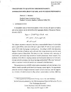
FIG. 1. Oscilloscope traces of a backswitch poling wave form over a 15.5mm-diam poled area of 0.5-mm-thick LiNbO3. Portions of the poling traces: the insert shows the complete programmed voltage wave form; 共a兲 shows the programmed voltage 共dotted line兲 and monitored voltage 共solid line兲 across the sample; and 共b兲 shows the poling current. In 共a兲, the difference between the programmed and monitored voltage traces during poling is due to voltage regulation by the ⬃20 mA current-limited power supply. The backswitching stage began when the duty cycle of the forward-switched domains reached approximately 90%.
Screening of the internal field appears to result primarily from the reorientation of dipolar defects in the bulk material with a time constant typically on the order of milliseconds.12,16 The stabilization stage serves to allow adequate screening of the internal field to prevent backswitching. During switching, the sign of the depolarization field changes, which, if the depolarization field is incompletely screened, results in lowering the total electric field and thereby slowing domain nucleation and growth. Conventional patterned-domain poling takes advantage of this effect by use of an insulating layer to prevent complete external screening as the domains propagate beyond the edges of the electrodes, and thus to stop domain growth at the desired duty cycle. The substrate preparation and beginning stages of backswitch poling are similar to the conventional method, however the stabilization stage of the voltage wave form is now preceded by an additional stage in which the applied voltage is rapidly lowered 关Fig. 1共a兲 insert兴.17–19 During this ‘‘low voltage’’ stage, spontaneous backswitching occurs, indicated by negative switching current, due to the internal field 关Fig. 1共b兲兴. The decaying voltage measured across the sample 关Fig. 1共a兲兴 reflects the screening of the internal field. Termination of backswitching and stabilization of the domains are accomplished by applying an external voltage larger than the instantaneous value of the decaying voltage 关Fig. 1共a兲兴. The rapid removal of the external voltage leads to domain nucleation under the edges of electrodes, similar to that of conventional forward switching, but at higher spatial density. In addition, sideways motion of the residual domain walls occurs during backswitching. These processes lead to high-fidelity short-period domain structures. Figures 2共a兲 and 2共b兲 show uniform 4-m-period domains in 0.5-mm-thick periodically poled LiNbO3.
Batchko et al.
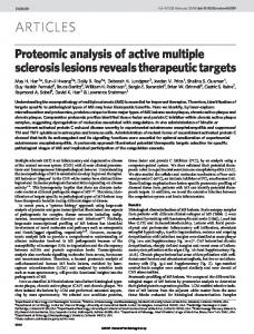
FIG. 2. 4-m-period domains in backswitch poled 0.5-mm-thick LiNbO3 substrate: 共a兲 y surface; and 共b兲 z⫺ surface view. Temperature-dependent phase matching for 460 nm SHG is shown in 共c兲.
Using this material, 5-cm-length devices were characterized for continuous wave 共cw兲 single-pass SHG of blue light.20 Using a cw Ti:sapphire pump laser near confocally focused to a 44 m waist radius, 6.1%/W efficient first-order generation of 60 mW at 460 nm was achieved, indicating an effective nonlinearity d eff⬇9 pm/V, approximately one half the nominal 18 pm/V value. Figure 2共c兲 is a nearly ideal tuning curve for 460 nm SHG phase matching versus temperature, indicating that the sample phase matches nominally over the full 5 cm length. Backswitched periodic domains have also been observed to form at the edges of the electrodes,12 thereby enabling the formation of domain periods at multiples of the spatial frequency of the electrode structure. LiNbO3 wafers were patterned with 10-m-period, 2-m-width stripe electrodes and poled over 56-mm-diam circular regions. These samples
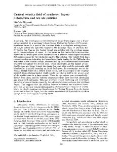
FIG. 3. Spatial frequency multiplication of domain structures by backswitch poling in 0.5-mm-thick LiNbO3 having 10-m-period 2-m-wide patterned electrodes. Spatial frequency doubling: 共a兲 z ⫹ surface; and 共b兲 y surface view. Spatial frequency tripling: 共c兲 z ⫹ surface; and 共d兲 y surface view. In 共d兲, the higher magnification in the x direction was obtained by using a tilted cross section. Downloaded 17 Mar 2007 to 171.64.87.117. Redistribution subject to AIP license or copyright, see http://apl.aip.org/apl/copyright.jsp
Batchko et al.
Appl. Phys. Lett., Vol. 75, No. 12, 20 September 1999
were forward poled until the duty cycles of the domains reached approximately 50%; they then suffered electrical breakdown near the o-rings of the poling fixture. The breakdown occurred before the stabilization voltage was applied and the domains were therefore allowed to spontaneously backswitch. Figure 3共a兲 is a z⫹ surface image taken from one of these wafers, which demonstrates the possibility of spatial frequency doubling of 10-m-period domains. In this case, the domain depth is typically 50–100 m for 1 m domain widths 关Fig. 3共b兲兴. Figure 3共c兲 shows another portion of the same wafer, with spatial frequency tripling of the 10-mperiod electrode pattern on the z⫹ surface. In this case, the additional submicron-wide domains penetrate 20–50 m deep 关Fig. 3共d兲兴. Backswitch poling in LiNbO3 enables higher fidelity and shorter period domain patterning of thick substrates than can be achieved with conventional poling. Future work will include the extension of this technique to other ferroelectric materials. Further studies to elucidate the mechanism of the spatial frequency multiplication, and control it through variation of the duty cycle of the electrodes and duration of backswitching, may enable waveguide devices having sub-m domain structures. This work was supported in part by Lawrence Livermore National Laboratory. The authors thank Crystal Technology, Inc. for the generous donation of the LiNbO3 substrates used in this work. The authors also thank Levent Erman and the Cohereat Laser Group for technical assistance and the use of lasers.
1675
R. L. Byer, J. Nonlinear Opt. Phys. Mater. 6, 549 共1997兲. K. Mizuuchi and K. Yamamoto, Opt. Lett. 21, 107 共1996兲. 3 J.-P. Meyn and M. M. Fejer, Opt. Lett. 22, 1214 共1997兲. 4 G. W. Ross, M. Pollnau, P. G. R. Smith, W. A. Clarkson, P. E. Britton, and D. C. Hanna, Opt. Lett. 23, 171 共1998兲. 5 W. P. Risk and S. D. Lau, Appl. Phys. Lett. 69, 3999 共1996兲. 6 K. Mizuuchi, K. Yamamoto, and M. Kato, Appl. Phys. Lett. 70, 1201 共1997兲. 7 M. Oron, M. Katz, D. Eger, G. Rosenman, and A. Skliar, Electron. Lett. 33, 807 共1997兲. 8 G. D. Miller, R. G. Batchko, W. M. Tulloch, D. R. Weise, M. M. Fejer, and R. L. Byer, Opt. Lett. 22, 1834 共1997兲. 9 M. Yamada, N. Nada, M. Saitoh, and K. Watanabe, Appl. Phys. Lett. 62, 435 共1993兲. 10 L. E. Myers, R. C. Eckardt, M. M. Fejer, R. L. Byer, W. R. Bosenberg, and J. W. Pierce, J. Opt. Soc. Am. 12, 2102 共1995兲. 11 G. D. Miller, R. G. Batchko, M. M. Fejer, and R. L. Byer, Proc. SPIE 2700, 34 共1996兲. 12 G. D. Miller, Ph.D. thesis, The Stanford University, 1998. 13 L. E. Myers, Ph.D. thesis, The Stanford University, 1995. 14 L.-H. Peng, Y.-C. Fang, and Y.-C. Lin, Appl. Phys. Lett. 74, 2070 共1999兲. 15 V. Gopalan and M. C. Gupta, Appl. Phys. Lett. 68, 888 共1996兲. 16 V. Gopalan, T. E. Mitchell, and K. Sicakfus, Solid State Commun. 109, 111 共1999兲. 17 V. Y. Shur, E. L. Rumyantsev, R. G. Batchko, G. D. Miller, M. M. Fejer, and R. L. Byer, Ferroelectrics 共to be published兲. 18 V. Y. Shur, E. L. Rumyantsev, R. G. Batchko, G. D. Miller, M. M. Fejer, and R. L. Byer, Phys. Solid State 共to be published兲. 19 V. Y. Shur, E. L. Rumyantsev, R. G. Batchko, G. D. Miller, M. M. Fejer, and R. L. Byer, Proceedings of the 11th International Symposium on Applications of Ferroelectrics, 24–27 August 1998, Piscataway, NJ 共IEEE, New York, 1998兲, pp. 399–405. 20 R. G. Batchko, M. M. Fejer, R. L. Byer, D. Woll, R. Wallenstein, V. Y. Shur, and L. Erman, Opt. Lett. 24, 1293 共1999兲. 1 2
Downloaded 17 Mar 2007 to 171.64.87.117. Redistribution subject to AIP license or copyright, see http://apl.aip.org/apl/copyright.jsp