Band-Pass-Filter with Balun Function from IPD Technology Kai Liu, Robert Frye*, and Roger Emigh STATS ChipPAC, Inc. 1711 West Greentree, Suite 117 Tempe, Arizona 85284, USA Tel: 480 222 1700
[email protected]
* RF Design Consulting, LLC 334 B Carlton Avenue Piscataway, NJ 0885 USA Tel: 908 217 5999
[email protected]
Port3
L2=L4_1
L1 Q= n /a
L2 Q=n/a
Q=n/a C6
Q= n /a C1 0
C5 Q=n/a
L1=L3_1
Q=n/a C1
C3 Q=n /a
0 Q=n /a C1 1
C4 Q=n /a
L 2 =L 4 _ 2
Q=n/a C12
L 1 =L 3 _ 2
Port1
Q= n /a C8
978-1-4244-2231-9/08/$25.00 ©2008 IEEE
BPF+Balun Design The circuit topology shown in Fig. 1 was selected after evaluating its ideal performance against the customer specifications (Table 1). In the ideal circuit, the typical Qfactors for inductors (25.0) and capacitors (100.0) are based on measurement results at the defined frequency band. However, Q factors of inductors depend on several factors: inductance value, inner opening of the coils, metal width, etc. In general, the smaller the inductance, the higher the Q factor. For example, a Q value of 60.0 at 8.0 GHz can be achieved for a 0.5 nH IPD inductor.
Q=n /a C7
Port2
0
BPF
Q= n /a C9
Introduction In a wireless communication system, a WLAN system for example, there are baseband IC, voltage regulator, RF transceiver, RF switch, and a large number of passive components (e.g., LCs and filters). Typically, these passive components consume 60%-70% of the footprint area. These passive components can be made in various formats, such as LTCC parts, IPD parts, or embedded in laminate substrates. There is clear indication that the overall size-reduction relies heavily on the reduction of these passive components (LCs and function blocks). Conventional passive components, which are most widely used for wireless products, are made from ceramic[4][5], due to its good electrical and thermal behavior. However, further reducing the footprint and height of ceramic components presents a serious challenge on performance and reliability. Integrated Passive Device (IPD) technology based on Silicon wafer process has been in great interest in the past decade. This process is well familiar to the semiconductor industry. In the process, high density capacitors, high Q inductors, and large value resistors can be made. The component designs use finer width and spacing, creating less parasitic effect, and this is the foundation from which smaller RF passive circuits can be built. There have been products incorporating individual filters and baluns [1][2]. Most of them are transmission-line type
filters and baluns developed for RF applications. The limitation of circuits using transmission-line topology is that their sizes are in multiple of ¼ wavelength. For most wireless applications, such as for cellular phone and WiFi, WiMAX, in which the RF frequency is lower than 6.0 GHz, lumped LC type circuits provide a dominate advantage for size-reduction [3][4][5][6][7][8]. In the following sections, we will present a balanced filter (2.45 GHz band) using lumped LC approach, from design to characterization.
C2 Q=n /a
Abstract Band-pass-filters (BPF) and baluns are critical components in the RF channels. Conventional discrete component solutions, like those from LTCC technology, use separate parts for these two functions. As miniaturization is becoming a trend for cost-reduction of wireless products, there is a need to make these devices in smaller form-factors. Integrated Passive Devices (IPD) technology, using Silicon wafer process techniques, enables smaller form-factor components for RF applications. Typically, compared to discrete LTCC parts, an IPD BPF can be three to five times smaller, and an IPD balun can be two times smaller. We have not only achieved smaller IPDs for these individual function blocks, but have also combined two function-blocks to create a single integrated component, which further reduces the overall size while maintaining good electrical performance. An advanced design methodology has been adopted based on EM simulation for making these IPDs. Good correlation is seen between simulation and test, and the result is that firstrun pass has been achieved in the majority of our designs.
0
Balun
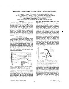
Figure 1. Circuit Topology for a balanced filter. There are four inductors (L1, L2, L3, L4) in this circuit. Three of them are used for a BPF, which is equivalently a 3pole filter. The last inductor (L4_1, L4_2) is used as the secondary inductor in a magnetically coupled balun. To reduce the size of the circuit, we use the inductor (L3_1 and L3_2) at the output stage of the BPF as the primary inductor of the balun. Because the size of inductors are much larger than capacitors, their size will dominate the overall circuit and eliminating even one inductor serves to reduces the overall size noticeably.
718
2008 Electronic Components and Technology Conference
of the tuning process. If the balun were implemented in an ideal way, this capacitance would be infinite, representing a short circuit. The inductance values and the coupling coefficient (K12) for the primary and secondary coils of the balun are shown in Fig. 2. It should be noted that the primary and the secondary coils have slightly different inductance due to unequal length that was required for ease of routing and connection.
Table 1. Electrical Specifications for a BPF + Balun functions.
Insertion Loss Return Loss Attenuation 1 Attenuation 2 Attenuation 3 Amplitude Imbalance Phase Imbalance
Frequenc y 2.42.5GHz 2.42.5GHz 1.8 GHz 4.8 GHz 7.2 GHz 2.42.5GHz 2.4-2.5 GHz
Specs
Unit
2.5
dB
15.0 18.0 20.0 35.0
dB dB dB dB
1.0
dB Degre e
5.0
Table 2. Component values for the balanced filter.
In a typical balun circuit, a center-tap is provided to feed DC voltage for the active devices (LNA, PA, etc) that are connected to it. However, for this particular IPD, a DC blocking capacitor (C12) is instead needed at the center-tap in order to avoid shorting the DC power supply which is already provided internally inside the customer IC. Selection of the DC blocking capacitor is somehow empirical. Of course, the larger the blocking capacitance, the better the electrical performance. But larger capacitance requires larger area to implement, which is not cost-effective. After evaluating the performance of different capacitance values, we found a capacitance larger than 7.0 pF is sufficient in this application. In actual layout, an 8.25pF capacitor was selected in the given space of specification. In the circuit-level simulation, that was done using ADS, a perfect balance property is expected since there is no parasitic and loss for the perfect coupled coils. But in actual layouts, parasitic from the two coupled coils, loss, and added traces contribute to the imbalance. In our design process, 0.6-0.8 coupling coefficient (K12) can typically be achieved for two magnetically coupled coils. The self and mutual inductance (Li,j), as well as the coupling coefficient (Ki,j) for the two coupled coils, are defined as follows,
Li , j = imag ( Z i , j ) / 2πf
(1)
K i , j = Li , j / Li ,i ⋅ L j , j
(2)
In the ADS circuit model, this coupling coefficient was fixed (to 0.7, for example). The LC values of this circuit were then optimized against the given specifications. The component values for the ideal circuit topology after optimization is summarized in Table 2. Implementation of the shunt capacitor C9 is also somehow empirical. The purpose of adding the C9 is to have better balance property from this IPD. In the ideal circuit model, the effect of C9 for balance property can not be shown. But when optimizing the balance property from a physical layout, this capacitor is useful and necessary for ease
C1
C2
C3
C4
C5
C6
L1
L2
2.72
3.88
4.8
1.88
0.5
3.17
1.9 L4_1 (L4_2) 2.06
C7
C8
C9
C10
C11
C12
2.4 L3_1 (L3_2)
2.52
0.56
5.94
2.2
2.2
8.25
1.9
The layout of the inductors and capacitors is implemented using a proprietary RCL generation tool which complies with the design rules. For this BPF+ Balun circuit, we adopted a backward layout approach – layout the coils (L3 and L4) of the balun first. The electrical property of the coils was then obtained from EM simulation and was used to replace the ideal coupled coils model in ADS. This hybrid circuit model was again optimized to find the component values of the rest circuit. The updated inductors (L1 and L2), although their values were not changed dramatically, were implemented accordingly and their electrical models (in S-parameter files) were obtained through electromagnetic (EM) simulation in a similar manner. At this point, all the coils/inductors were represented in EM models (in s-parameters) in the ADS circuit. This circuit was optimized again and the updated capacitors were available. These capacitors were implemented at the last stage. After interconnection was added to form a functional circuit, the preliminary layout was simulated using an EM solver. In most cases, the response from the initial layout departs from the schematic circuit’s predicted response, due to the parasitic effect of the added traces for interconnection. A number of internal ports between electrodes of the capacitors are assigned for tuning them for a desired response in our design process. Detail of the EM based optimization can be found in [9]. From the wafer process, the capacitance density is 330pF/mm2, which is high enough to most of RF applications. In a typical actual layout, capacitors are much smaller in size than the inductors, so they are not the bottleneck as far as overall-size is concerned. Therefore, physically tuning the capacitor size (making them slightly smaller or larger) will not alter very much the parasitic coming from rest of the layout. This is the fundamental reason that makes this capacitor-based tuning approach the preferred method.
719
2008 Electronic Components and Technology Conference
Inductance (H)
-0.65
5E-9
-0.70
4E-9
-0.75
3E-9
-0.80
2E-9
-0.85
1E-9
Coupling Coefficient
6E-9
the bumping process, and the stand-off effect as well as PCB grounding effect was taken into account in the IPD design.
-0.90 0
2
4
6
8
10
5E-9
12
Figure 2. Inductance and coupling coefficient (K12) of two coupled coils for the balanced filter. Fig. 3 is a 3D conceptual illustration of the balanced BPF. There are ten bumps for this IPD (called a flip-chip IPD). Among these bumps, three are for the unbalanced input and balanced outputs. The rest of the bumps are just for electrical ground and they are connected through a ground ring. On such a ground ring, the electrical potentials are not equal due to “ground inductance”. For a ground ring surrounding a typical IPD (say 1.5mm x 1.5mm), the ground inductance can be in 0.6 nH-1.0 nH range depending on the width of the ring [10]. However, it is hard to use a fixed ground inductance value in a circuit-level simulation to represent this ground inductance effect, because not each port has the same ground inductance value. To design an IPD having such a ground ring, EM simulation including both the intrinsic IPD layout and the ground ring has to be carried out. It should be noted that the actual circuit components (LCs) are located on the top 10% of the silicon stack. When the IPD is in flip-chip configuration, there is usually 75.0-125.0 um of ball stand-off from the standard process. The inductor coils see their proximity in this stand-off range, which will change both the inductance and the Q factor of an inductor, compared to an inductor in wire-bonging configuration (face-up).
40
4E-9
30
3E-9 20 2E-9
Q factor
Inductance (H)
freq, GHz
10
1E-9
Stand off=75um, 100um, 125um.
0
0 0
2
4
6
8
10
12
14
freq, GHz
Figure 4. Inductance and Q. factor for a 2.2 nH inductor in flip-chip configuration. Measurement and Characterization a) IPD Probed on Test Board To directly compare the simulation data, we made a 4layer test laminate strip, on which the IPD was mounted by flip-chip technique. Short 50-ohm line traces are added and terminated with G-S-G pads for characterization on the test board. The finished IPD is in size of 1.5mm x 1.5mm x 0.4 mm.
IPD Flipped
Bumps Input
Capacitors
Ground Ring
Probing Ports
Balanced Output
Figure 5. IPD flipped on to a teat board. Probable pads (G-S-G) are made on the test board for probing characterization of the three port device.
Figure 3. Bumped IPD illustration. In Fig. 4, as the stand-off varies from 75.0 um to 125.0 um. The Q factor peak increases from 35 to 37 (not too much), but the inductance jumps about 10 % from 2.17 nH to 2.4 nH. In circuit response, this translates into a downwardshift response. In addition, the change for both Q and inductance saturates for a stand-off larger than 125.0 um, as the trend is showing. In general, larger than 125.0 um standoff is preferred, since it will result in more viable designs. But in some cases making bigger/larger bumps is cost-prohibitive. In this design, we selected a stand-off of 75.0 um for ease of
Two-port measurement was made one at a time for this three port device, while the third port was alternatively terminated with a 50 ohm terminator connected to the third probing port. Then the measured data was assembled to derive the differential-mode and common-mode s-parameters, which are defined as follows.
720
(
DIFF = 20 log10 (S 21 − S 31 ) / 2
)
(3)
2008 Electronic Components and Technology Conference
(
COMM = 20 log10 (S 21 + S 31 ) / 2
)
(4)
Probe Station
The differential-mode and common-mode s-parameter are plotted in Fig. 6. Insertion loss for differential mode is 2.2 dB. Return loss and attenuation specs in Table 1 have all been met. The design methodology gives a very accurate prediction, which can be seen from the comparison between simulated and measured curves in the entire frequency band.
30 Return Loss
10
-20
-10
-30 -40
-30
-50
Common Mode (dB)
Differential Mode (dB)
0 -10
Temperature Controller
Figure 8. Measurement facility for wafer probing.
-50
-60 0
1
2
3
4
5
6
7
8
freq, GHz
Figure 6. Differential and Common mode S-parameter for the balanced filter. Solid: from measurement. Dash: from simulation.
185
0
180
-1
175 2.4
m2 m3 m4 freq=5.500GHz freq=5.500GHz freq=5.500GHz dB(S(1,2))=-1.467 dB(S(3,4))=-1.649 dB(S(5,6))=-1.846 -1
Temp=-40 0C, Room Temp, 90 0C
Insertion Loss (dB)
1
Phase Imbalance (degree)
Amplitude Imbalance (dB)
The common-mode rejection at the pass-band (2.4-2.5 GHz) is larger than 30.0 dB, meaning a good balance property has been obtained for this balanced filter. The balance property of this device is plotted in Fig. 7. Within the passband, the amplitude imbalance is 0.5 dB MAX and the phase imbalance is 3.0 degree MAX, respective to 180.0 degree.
Temperature dependence characterization was performed on a similar IPD made using the same wafer process technology. The measurement was conducted through onwafer probing. The probe station chuck was linked to a temperature controller by Nucleus software using GPIB communication (Fig. 8). The temperature was set in the Nucleus software thermal control. When the controller reached the setting temperature, an additional 15 minutes were allowed to further stabilize the temperature. Then the calibration was carried out and so was the measurement. Fig. 9 plots the measured insertion loss variation with temperature for a 5.5 GHz band IPD filter. The degradation at temperature of +90 C is about 0.2 dB, which would be considered acceptable in most of applications.
2.5
freq, GHz
m2 m3 m4 -2 4.5
Figure 7. Measured balance property of the balanced filter.
5.5
6.5
freq, GHz
b) IPD Temperature Dependence In reality, this IPD device will be used in a temperature variant environment. It is necessary to characterize the loss property over the expected temperature range, typically specified to be from -40C to +90C. For an IPD, additional loss at higher temperature is from the electrical degradation of metal, substrate, via connection, etc. The dominant factor is the change (decrease) in metal conductivity as the temperature increases.
Figure 9. Temperature impact on insertion loss of an IPD filter.
For each IPD product, it is necessary to know its loss property in the pass band before it is actually manufactured. This requirement is usually set in specifications, as minimum and maximum insertion loss numbers. Attenuation performance with temperature is not a concern because only a minor portion of attenuation is changed. For this IPD measured above, EM simulation taking into account of temperature dependence has been carried out.
721
2008 Electronic Components and Technology Conference
The EM solver has an option to input difference temperature for simulation. To verify the simulation over temperature, both simulated and measured data are plotted together. As shown in Fig. 10, the simulation predicts the insertion loss variation with temperature very well, except the absolute values. The insertion loss difference between different temperature (-40 C, room temperature, +90 C) is close to the measured data. The temperature dependence, to the best of our knowledge, is among the best class of passive filters. After confirmation from the measurement above, the simulation method may be used to investigate insertion loss at other temperatures. The insertion loss variation between room temperature and 90 C is very small - less than 0.2 dB. The Fig. 10 just exaggerates the difference using the scale.
Insertion Loss (dB)
-1
loss could be 3.0 dB - 5.0 dB in difference. In our simulation, the return loss difference is within 2.0 dB, which is a very good number, given the return loss nature above. In other words, our simulation scheme is very suitable for IPD products. Besides the insertion loss change over temperature, it is also needed to know the attenuation change over temperature, especially at the sharp transition area around 6.5 GHz in Fig. 11. In some applications where attenuation requirements are critical, attenuation change over temperature has to be controlled with certain range. Measured data over temperature is plotted in Fig. 12. From the lowest temperature (-40 C) to the highest temperature (+90 C), the frequency shift is about 30.0 MHz, at the -20 dB attenuation crossing line. This gives a relative change in 0.46%, which is acceptable for most of RF applications. The frequency shift property has also been characterized on some other IPDs working at different bands. For all the IPDs tested, the frequency shift is within 0.5% from -40 C to +90 C.
m5 freq=6.432GHz dB(S(1,2))=-20.045
m6 freq=6.417GHz dB(S(3,4))=-19.992
m7 freq=6.402GHz dB(S(5,6))=-19.973
0
-2 5.5
-40 C, Room Temp, +90 C
6.5
Insertion Loss (dB)
4.5
freq, GHz
Figure 10. Insertion loss variation with temperature. Solid lines: from measurement. Dot lines: from simulation.
m7 m6 m5 -20
-40 6.2
Fig. 11 depicts the data at room temperature for the entire frequency band. It is barely to see the difference in the pass band. In the low-side and high-side stop bands, very good agreements are also achieved.
S-parameter (dB)
-10
-20
-30 2
3
4
5
6
7
Figure 12. Measurement data: frequency shift with temperature.
Conclusions A balanced filter for 2.45 GHz is achieved in small formfactor using Silicon based IPD technology. This IPD is the smallest device that, to the best of our knowledge, comprises these functions, and is well suitable for RF SiP applications. Excellent balance and filter property is obtained from this device. The close agreement between simulated and measured data validates the viable design approach. The temperature dependence of IPD products using Silicon technology has been characterized. In general, IPD products are very robust, working in a temperature variant environment.
0
1
6.7
freq, GHz
8
freq, GHz
Figure 11. Comparison between simulated and measured Sparameters at room temperature.
In simulation for microwave circuits (e.g, RF filter), it is very difficult to predict the return loss very well. Return loss is very sensitive to small layout features. For two almost identical layouts, although the insertion losses can be just within small change (a couple tenth of dB, e.g.,), the return
Acknowledgments The authors thank Yaijian Lin, Badakere Guruprasad, Haijing Cao, and Phoo Hlaing for their help and assistance in the fabrication and characterization of the IPD.
722
2008 Electronic Components and Technology Conference
References 1. Liu, A.Q., et al., “Broad-Band Band-Pass and Band-Stop Filters with Sharp Cut-off Frequencies Based on Series CPW Stubs,” Proc 2006 International Microwave Symposium, 2006, pp. 353-356. 2. Na, Won, et al, “Ring Hybrid Balun with Good Amplitude and Phase Balance,” Proc 2007 International Microwave Symposium, 2007, pp. 1769-1772. 3. Ang, K.S., et al, “Analysis and design of miniaturized lumped-distributed impedance-transforming baluns,” IEEE Trans-MTT, Vol. 51, (March 2003), pp. 1009-1017. 4. Tang, C.W., et al, “LTCC-MLC chip-type balun realized by LC resonance method,” Electronics Letters, Vol. 38, (2002), pp. 519-520. 5. Tang, C.W., et al., “A semi-lumped balun fabricated by low temperature co-fired ceramic,” IEEE MTT-S Int. Microwave Symp. Dig, 2002, pp. 2201-2204. 6. Park, J. C., et al, “Fully Embedded 2.4GHz LC-Balun into Organic Package Substrate with Series Resonant Tank Circuit,” Proc 2007 International Microwave Symposium, 2007, pp. 1901-1904. 7. Liu, Kai, et al, “Small Form-Factor Integrated Passive Devices for SiP Applications,” Proc 2007 International Microwave Symposium, 2007, pp. 2117-2120. 8. Frye, Robert, et al, “A Hybrid Coupled-Resonator Bandpass Filter Topology Implementedon Lossy Semiconductor Substrates,” Proc 2007 International Microwave Symposium, 2007, pp. 1757-1760. 9. Liu, Kai, et al, “Full-Circuit Design Optimization of a RF Silicon Integrated Passive Device,” Proc 2006 Electrial Performance of Electrical Packages, 2006, pp. 327-330. 10. Liu, Kai, et al, “Chip Scale Module Package for WLAN Module Application,” Proc 2007 ECTC, 2007, pp. 14091414.
723
2008 Electronic Components and Technology Conference