Jaypee Institute of Information Technology University, Noida-201 307, India ... the carrier frequency offset that destroys the orthogonal properties of OFDM ...
PIERS Proceedings, Moscow, Russia, August 18–21, 2009
1244
Bandwidth Efficient Inter-carrier Interference Cancellation Technique for OFDM Digital Communication Systems Akhil Kamboj1 , Abhinav Keshari1 , Vivek K. Dwivedi1 , and G. Singh2 1
Department of Electronics and Communication Engineering Jaypee Institute of Information Technology University, Noida-201 307, India 2 Department of Electronics and Communication Engineering Jaypee University of Information Technology, Solan-173 215, India
Abstract— Orthogonal Frequency Division Multiplexing (OFDM) is a promising technique for the broadband wireless multimedia communication systems. This system is very sensitive to the carrier frequency offset that destroys the orthogonal properties of OFDM sub-carriers and introduces inter-carrier interference (ICI) which degrades the bit error rate (BER) performance. In this paper, we have proposed a novel bandwidth efficient technique which have bit error rate comparable to that of conjugate cancellation method. We also discussed carrier-tointerference ratio (CIR) and compared with the other reported literature. 1. INTRODUCTION
Future wireless communication systems are expected to offer extremely high data rates with appropriate link quality over poor transmission environments. One efficient way to achieve this is by using OFDM technique because of its sufficient handling of radio channel impairments. Its bandwidth efficiency is due to overlapping of the orthogonal sub-carriers. Despite its benefits, its major problem is its sensitivity to frequency offset. The frequency offset can result from a Doppler shift due to a mobile environment, as well as from carrier frequency synchronization error. Such frequency offset causes the loss of carrier’s orthogonality and hence ICI will occur. Various schemes have been proposed in literature [1–4] for mitigating the ICI. The scheme proposed in [1] requires to modulate one data symbol on to the next sub-carrier with predefined inversed weighting coefficients “−1”. This concept of predefined weighting coefficients makes the ICI component in the received signal to cancel among themselves. The scheme proposed in [2] requires data to be sent on two paths. The first path employs a regular OFDM algorithm and the second path uses the conjugate transmission of the first path. However, the above schemes in [1–4] have bandwidth efficiency equal to half that of standard OFDM. In this paper, we have proposed a new bandwidth efficient technique and compared its performance against existing techniques [1–4] for different values of frequency offsets. The model of transmitter and receiver of regular OFDM system is explained in Section 2. Section 3 presents the proposed scheme and the corresponding sequential and parallel architectures. The simulation results are discussed in Section 4 and finally, Section 5 concludes the works. 2. OFDM SYSTEM MODEL
In an OFDM system, the input bit stream is multiplexed into N symbol streams, each with symbol period T , and each symbol stream is used to modulate parallel, synchronous sub-carriers. The sub-carriers are spaced by 1/N T s in frequency, thus they are orthogonal over the interval (0, T s). A typical discrete-time baseband OFDM transceiver system is shown in Fig. 1. First, a serial-toparallel (S/P) converter groups the stream of input bits from the source encoder into groups of log2 M bits, where M is the alphabet of size of the digital modulation scheme employed on each sub-carrier A total of N such symbols, Xl , are created. Then, the N symbols are mapped to bins of an inverse fast Fourier transform (IFFT). These IFFT bins correspond to the orthogonal sub-carriers in the OFDM symbol. Therefore, the OFDM symbol can be written as: x(n) =
N −1 2πnl 1 X X l ej N N
(1)
l=0
where the Xl ’s are the baseband symbols on each sub-carrier. The digital-to-analog (D/A) converter then creates an analog time-domain signal which is transmitted through the channel. At the
Progress In Electromagnetics Research Symposium Proceedings, Moscow, Russia, August 18–21, 2009 1245
Figure 1: Block diagram of standard OFDM system.
receiver, the signal is converted back to a discrete N point sequence y(l), corresponding to each sub-carrier. This discrete signal is demodulated using an N -point fast Fourier transform (FFT) operation at the receiver. The demodulated symbol stream is given by: Y (l) =
N −1 X
y(n)e
−2πnl N
+ Wl
(2)
l=0
where, W (m) corresponds to the FFT of the samples of w(n), which is the Additive White Gaussian Noise (AWGN) introduced in the channel. 3. PROPOSED SCHEME
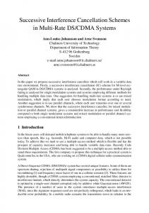
In this scheme a two path algorithm is used to send the data as shown in Fig. 2. The first path sends a specially modulated data symbols which results from weighted subtraction of an even numbered BPSK symbol and its consecutive symbol. The second path uses the conjugate of a similar type of specially modulated data symbols which results from weighted addition of an even numbered BPSK symbol and its consecutive symbol. 3.1. Modulation
Assume a0 , a1 , . . . , a2N −1 be the first 2N BPSK symbols as in [5]. On the first path the transmitted symbols Xl are constrained so that X0 = a0 − a1 , X1 = a2 − a3 , . . . , XN −1 = a2N −2 − a2N −1 . Similarly, on the second path the transmitted symbols Xl0 are constrained so that X0 = a0 + a1 , X1 = a2 + a3 , . . . , XN −1 = a2N −2 + a2N −1 . Here the predefined weighting coefficients for BPSK symbols is “1”. N -point IFFT of the modulated data symbols from first and second path is
Figure 2: Simulation block diagram of proposed system model.
PIERS Proceedings, Moscow, Russia, August 18–21, 2009
1246
performed separately. Data symbols from the first path is as it is converted from digital to analog and transmitted whereas data symbols from the second path is conjugated, converted to analog and then transmitted on successive Time Division Multiplexing (TDM) frame. Data signal sent on first path is: N −1 2πnl 1 X x(n) = Xl ej N where Xl = a2l − a2l+1 (3) N l=0
Similarly, data signal sent on second path is: x0 (n) =
N −1 2πnl 1 X (Xl0 ) ∗ e−j N where Xl0 = a2l + a2l+1 N
(4)
l=0
3.2. Demodulation
On being received and converted into digital form these signals look like y(n) = y 0 (n) =
N −1 2πn(l+ε) 1 X Xl ej N + wn N
(5)
1 N
(6)
l=0 N −1 X
(Xl0 )∗e−j
2πn(l−ε) N
+ wn0
l=0
After conjugating the signal from the second path, leaving the signal from first path as it is, and thereafter performing N -point FFT of these signals separately, they look like Y (k) = Y 0 (k) =
N −1 X l=0 N −1 X
Xl S(l − k) + wl
(7)
Xl T (l − k) + wl0
(8)
l=0
where k = 0, 1, 2, . . . , N − 1. The S(l − k) and T (l − k) is defined as ICI coefficient between lth and kth sub carriers which can be expressed as: ¶ ¶ µ µ sin (π (l + ε − k)) 1 ¡ ¢ S (l − k) = (l + ε − k) (9) · exp jπ 1 − π N N sin N (l + ε − k) ¶ ¶ µ µ sin (π (l − ε − k)) 1 ¡ ¢ T (l − k) = (l − ε − k) (10) · exp jπ 1 − π N N sin N (l − ε − k) For receiving the even numbered BPSK symbols (i.e., a0 , a1 , . . . , a2l−2 ) Y (k) is added to Y 0 (k) and further divided by 2. Similarly, for receiving the odd numbered BPSK symbols (i.e., a1 , a3 , . . . , a2l−1 ) Y (k) is subtracted from Y 0 (k) and further divided by 2. 4. SIMULATION RESULTS AND DISCUSSION
For simulation, modulation is BPSK with N = 64 and guard interval 7. In Fig. 3, CIR of proposed scheme is compared to the conjugate cancellation scheme and it is observed that for frequency offset, ε = 0.25 to 0.5 proposed scheme is better than conjugate cancellation. Figs. 4, 5, and 6 show the comparison of BER amongst self cancellation method, conjugate cancellation and proposed scheme for normalized frequency offset 0.05, 0.1 and 0.15, respectively. For frequency offset 0.05, by using self cancellation scheme, at SNR = 10 dB, BER is just greater than 10−1 and by using proposed scheme, at SNR = 10 dB, BER is just less than 10−1 For frequency offset 0.15, by using self cancellation scheme, at SNR = 10 dB, BER is greater than 10−1 and by using proposed scheme, at SNR = 10 dB, BER is just greater than 10−1 . Also the bandwidth efficiency of proposed scheme is double that of self cancellation. So, the proposed scheme is better than the self cancellation scheme. The BER for both, the conjugate cancellation scheme as well as proposed scheme is comparable at SNR = 10 dB, for offset values 0.05 and 0.15. Here also the bandwidth efficiency of proposed scheme is double that of conjugate cancellation scheme. So the proposed scheme is better than the conjugate cancellation scheme.
Progress In Electromagnetics Research Symposium Proceedings, Moscow, Russia, August 18–21, 2009 1247 10
80
0
proposed scheme CC scheme
60
10
-1
BER
CIR (dB)
40
20
10
-2
0
10
Proposed scheme
-3
Conjugate Cancellation
-20
Self Cancellation Standard OFDM
-40
0
0.05
0.1
0.15 0.2 0.25 0.3 0.35 Normalized Frequency Offset ε
0.4
0.45
0.5
10
0
10
0
2
10
-1
-2
6
8
10 12 Eb/No(dB)
14
16
18
20
-2
Proposed scheme
-3
Proposed scheme Conjugate Cancellation Self Cancellation Standard OFDM
Conjugate Cancellation Self Cancellation Standard OFDM
10
4
-1
10
10
0
BER
BER
10
-4
Figure 4: BER comparison in AWGN channel (BPSK) N = 64, ε = 0.05.
Figure 3: (CIR) vs normalized frequency offset.
10
10
-4
0
10
2
4
6
8
10 12 Eb/No(dB)
14
16
18
20
Figure 5: BER comparison in AWGN channel (BPSK) N = 64, ε = 0.1.
-3
0
2
4
6
8
10 12 Eb/No(dB)
14
16
18
20
Figure 6: BER comparison in AWGN channel (BPSK) N = 64, ε = 0.15.
5. CONCLUSION
In this paper, we proposed a novel technique for OFDM systems which has double bandwidth efficiency than existing schemes as discussed in [1–4, 6]. The proposed scheme has better BER than self-cancellation for frequency offsets 0.05, 0.1, and 0.15. The BER of proposed scheme is comparable to conjugate cancellation for frequency offsets 0.05 and 0.1. For frequency offset greater than 0.15 conjugate cancellation performs better. Moreover, for frequency offsets 0.25–0.5 CIR of proposed scheme is better than that of conjugate cancellation. REFERENCES
1. Zhao, Y. and S.-G. Haggman, “Inter-carrier interference self-cancellation scheme for OFDM mobile communication systems,” IEEE Trans. Commun., Vol. 49, No. 7, 1185–1191, Jul. 2001. 2. Dwivedi, V. K. and G. Singh, “An efficient BER analysis of OFDM systems with ICI conjugate cancellation method,” PIERS Proceedings, 166–171, Cambridge, USA, July 2–6, 2008. 3. Yeh, H.-G., Y. K. Chang, and B. Hassibi, “A scheme for canceling inter-carrier interference using conjugate transmission in multicarrier communication systems,” IEEE Trans. Wireless Commun., Vol. 6, 3–7, Jan. 2007. 4. Armstrong, J., “Analysis of new and existing methods of reducing inter-carrier interference due to carrier frequency offset in OFDM,” IEEE Trans. Commun., Vol. 47, 365–369, Mar. 1999.
1248
PIERS Proceedings, Moscow, Russia, August 18–21, 2009
5. Proakis, J. G., Digital Communications, 4th Edition, McGraw-Hill Series, 2001. 6. Sathananantan, K. and R. M. A. P. Rajatheva, “Analysis of OFDM in presence of frequency offset and method to reduce performance degradation,” Proc. IEEE Globecom., Vol. 172–176, San Fransisco, CA, Nov. 2000. 7. Dwivedi, V. K. and G. Singh, “Inter-carrier interference cancellation scheme for OFDM systems,” Proc. National Conference on Wireless and Optical Communication (WOC-2007), 245– 248, India, 2007.