radiation pattern of an antenna array employs a directional array with only one .... steering of the beam is achieved by switching the feed position between the ...
IEEE TRANSACTIONS ON ANTENNAS AND PROPAGATION, VOL. 46, NO. 6, JUNE 1998
841
Base-Station Tracking in Mobile Communications Using a Switched Parasitic Antenna Array Stephanie L. Preston, Student Member, IEEE, David V. Thiel, Senior Member, IEEE, Trevor A. Smith, Student Member, IEEE, Steven G. O’Keefe, Member, IEEE, and Jun Wei Lu, Member, IEEE
Abstract—Base-station tracking in mobile communications benefits from a directional antenna and so requires direction finding technology. A novel technique for electronically directing the radiation pattern of an antenna array employs a directional array with only one active element and three parasitic elements operating near resonance. Three different methods of direction finding are assessed; a coarse angular location method, a precise angular location method assuming one incident beam, and a precise angular location method with multiple incident beams. An array with n elements, if used in conjunction with a relatively simple controller, can be used to resolve n 0 1 signals. This technology can be implemented using both wire and patch antenna-array elements and either linear or circular polarization can be used, lending the technology to applications in both terrestrial and satellite communications systems. Index Terms—Antenna arrays, mobile communication.
I. INTRODUCTION
I
N digital communications systems, it is possible to have a periodic break in the transmission of information without degrading the signal transmitted. This break in transmission can be used to optimize the communications channel. One factor that can greatly improve the channel is the use of a directional antenna system. In this paper, we propose that in between data segments, the mobile transceiver maintains the optimal channel by re-orienting the antenna system. This is only possible if the time required to perform the operation is sufficiently small and the directivity of the antenna is adequate. We suggest that an electronically steerable switched parasitic antenna array supported by a small digital controller can achieve these objectives, even in severe multipath environments. The solutions we suggest are evaluated in the context of time-domain multiple access (TDMA) in group special mobile (GSM) mobile telephone communications for use in base-station tracking but are far more generally applicable. When using directional antennas, intelligent high-speed direction-finding techniques are required and, in the case of a mobile transceiver, the system must have low-power requirements. With conventional directional antenna systems Manuscript received March 5, 1997; revised December 29, 1997. S. L. Preston was supported by a scholarship from the CSIRO Division of Telecommunications and Industrial Physics, Sydney Australia. This work was supported in part by research grants from the Australian Telecommunications and Electronics Research Board and the Australian Research Council. The authors are with the Radio Science Laboratory, School of Microelectronic Engineering, Griffith University, Nathan Qld, 4111 Australia. Publisher Item Identifier S 0018-926X(98)04873-X.
for initial signal acquisition and subsequent direction updates, a full 360 scan may be required. We propose a technique that will enable the updates to be minimized and allow the direction to be determined without a full 360 scan periodically. Current direction-finding techniques include conical scan, sequential lobing monopulse, and track-while scan [1], [2]. These techniques require the use of either mechanically rotating antennas, crossed loops or phased arrays. In direction finding, multiple incoming signals can result in an incorrect angular position being determined. A common method used to resolve multipath and/or multiple signals is the use of high-gain narrow-beam mechanically rotating antennas [1], [2]. This method can resolve two or more signals provided they are separated by an angle greater than the beamwidth of the antenna. Thus, the number of signals that can be detected depends on the beamwidth of the antenna. Other techniques for minimizing the impact of multipath interference involve the implementation of frequency hopping, polarization agility, and space diversity. A previous paper discusses the use of four directional arrays to reduce the fading caused by multipath signals [3]. This technique uses four separate arrays, each with a directional pattern, and requires switching between these arrays. The methods used to reduce the effects of multipath mentioned above have been successful, however, these systems are generally quite complex. Where possible, it is desirable to avoid mechanically rotating parts so that power consumption is kept to a minimum. The alternate methods have involved the use of phased arrays, allowing 360 rotation with no moving parts. This would seem an ideal solution, however, in order to track multipath signals, a full 360 sweep is required regularly so that the desired signal is distinguished from other spurious signals. This process is time consuming with both the phased array and the mechanically steerable arrays and with phased arrays it is also computationally intensive. Certain applications cannot afford the time spent in these cases, for example, with the TDMA modulation scheme used in GSM for mobile telephones, the minimum interval between frames is 4.038 ms. II. ELECTRONICALLY STEERABLE ANTENNA ARRAY The basic concept of an electrically steerable switchedparasitic antenna array has been presented previously [4], [5]. Near-resonance parasitic elements are used to create a directional electronically steerable antenna array. This technique can be applied to both wire antenna structures (e.g.,
0018–926X/98$10.00 1998 IEEE
842
IEEE TRANSACTIONS ON ANTENNAS AND PROPAGATION, VOL. 46, NO. 6, JUNE 1998
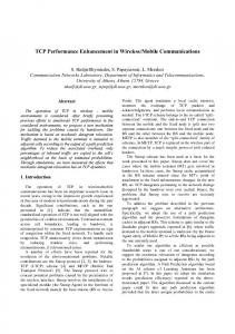
Fig. 1. A four-element monopole switched-parasitic antenna array
d = 0:27�, L = 0:25�, r = 0:625�, and
wire radius
a = 0:005�.
dipole or monopole elements) and patch arrays. In this paper, applications using a four-element monopole array operating at 1.5 GHz are discussed. The antenna array consists of one active element and three parasitic elements operating near resonance. The structure is shown in Fig. 1, giving all dimensions and the theoretical radiation pattern found; using NEC2 for all four directions is shown in Fig. 2. Electronic steering of the beam is achieved by switching the feed position between the four elements using a single-pole four-throw RF switch and then switching the parasitic elements in or out of resonance using appropriately biased RF - - diodes. III. DIRECTION FINDING The switched-parasitic antenna array described in the previous section has been proposed for use in a directionfinding system for the tracking of base stations in mobile communications. This system provides a simple directionfinding solution to both single- and multiple-signal detection. The array can be used in three different modes: Mode 1 coarse angular location of a single source; Mode 2 precise angular location of a single source; Mode 3 precise angular location of multiple sources. Modes 1 and 2 have been presented previously [6]. In all three cases, the primary input information is the total signal strength measured at each of the four switch positions and a knowledge of the 360 radiation pattern of the array. A. Mode 1 This technique tracks a source and electronically orients the beam of the antenna in such a way as to always be receiving the maximum incident signal regardless of the position of the receiver. For a single source and when precise determination of the angular location is not required, this technique provides a simple solution with low acquisition time. Using the four-element parasitic array described previously, with the four patterns shown in Fig. 2, the field strength at each of the four positions , , , and is detected sequentially. The maximum value is determined and the antenna is switched to the position that gives the maximum signal until a further update is required. The time taken to perform this operation is primarily limited by the speed of the analog-to-digital converter (ADC) of the controller. For example, a likely time
Fig. 2. Radiation pattern of four-element monopole array shown in Fig. 1 for all four switch positions with a single active antenna element calculated using NEC2.
would be 100 s using a standard MC68HC11 with 2-MHz clock. This method is similar to the four-array system used to minimize multipath fading [4]. When operating in this mode, it is necessary to constantly repeat the process of signal tracking, as it is not known in which section of the quadrant the signal lies. B. Mode 2 This mode of operation also requires the signal strengths , , , and at each of the four switch positions to be detected. The angular location can then be determined within 45 by the order and relative magnitudes of the four , , and , then received strengths. For example, if it is known that the signal lies in the quadrant . Then, if and , it is also known that the signal lies in the half closest to quadrant . This is demonstrated of quadrant graphically in Fig. 2. A more precise determination of the angle is then found by comparing the differences between the , , , etc. with the radiation signals, i.e., pattern and finding the angles on the radiation pattern that
PRESTON et al.: BASE-STATION TRACKING USING A SWITCHED PARASITIC ANTENNA ARRAY
843
As with modes 1 and 2, the array is switched between the four orthogonal positions sequentially and the total signal at each position , , , and is detected. From this and , the information, the object is to determine and , the strengths of the two incoming signals, and angular positions of the two incoming signals. The total measured signal strength for the first switch can be written position (1) and are the antenna gains at and for where patterns one and two, respectively. At the next position, 90 away from the first position, the would be new signal strength Fig. 3. Angle determination results in the presence of single incident signal.
020 dB noise for a
correspond to these differences. It should be noted that due to the determination of the angle within a 45 section first and due to the symmetry of the radiation pattern, it is only necessary to store half of the radiation pattern. With no noise present, this method provides an exact solution. The presence of noise will introduce some error into the angle determination, the extent of which is demonstrated graphically in Fig. 3. To obtain this information, the system was modeled using MATLAB and the random function was used to add normally distributed random noise to the incident signal. In this figure, noise of 20 dB has been added, introducing an error of less than 5 . It is only necessary to show one half of a quadrant as the other half will be identical. The time required for this mode is simply that required by the Mode 1 controller to access a look-up table. This is estimated to result in a total update scan time of less than 200 s. When operating in this mode, it is possible to predict the movement of a source in relation to the receiver by knowing the previous measurements. Therefore, it will not be necessary to perform full 360 measurements as it is extremely unlikely that the source will move through more than a 90 sector within the time between measurements. Once the angular position of the source has been initially determined, a dither algorithm will then be sufficient to continue tracking. This will shorten the time required for each measurement. This algorithm will not provide a solution if there are multiple signals within the same quadrant. If the signal with maximum strength lies in a different quadrant to the multipath signals then it is possible to track the desired signal with small error. C. Mode 3 This section of the paper concentrates on resolving two signals only, for example, a desired plus a multipath signal. If required, however, the technique can be extended to resolve three signals with the four-element array or more than this with the addition of more symmetrically positioned elements and slightly more processing.
(2) Similarly, we can write (3) and (4) Equations (1)–(4) can be rewritten as
(5)
is known at every From the radiation pattern, the gain and . angle and the task is then to solve for and for all combinations of and The solutions for are found using the following equations: (6) This process is then repeated using equations (7) and have the same The correct solution occurs when and for both sets of solutions. With value at the same and derived from (6) and noise added, the values of (7) will not be identical, so the closest match will be the best approximation to the true values and the variation in these values will be an indication of the noise level in the system. In order to solve for the relative strengths and angular positions of two incident signals, three equations and, therefore, three of the four switch positions are required. In general, with unknown an -element array it is possible to solve for signals. This algorithm will provide a solution for multiple signals within the same quadrant, however, the array does not have
844
IEEE TRANSACTIONS ON ANTENNAS AND PROPAGATION, VOL. 46, NO. 6, JUNE 1998
beamforming capabilities and so it is not possible to separate the signals. IV. CONCLUSION A novel electronically steerable antenna array using switched parasitic elements has direct application to direction finding in mobile communications systems for efficient basestation tracking. It has been shown that such an antenna can be used to determine the angular position of a distant source relative to the position of the receiver with minimal system requirements. With noise of 20 dB added to the system, the error in angle determination was found to be less than 5 . This system can also be used to resolve multiple signals with the addition of some simple processing tools. The number of signals resolvable depends on the number of elements of the signals. array. With elements, it is possible to resolve This antenna type provides a simple solution to direction finding without the complex mechanically steerable or phasing parts required by previously presented systems. ACKNOWLEDGMENT
David V. Thiel (M’81–SM’88) received the B.Sc. degree (honors) in physics from the University of Adelaide, Australia, in 1970, and the M.Sc. and Ph.D. degrees from James Cook University, Queensland, Australia in 1974 and 1980, respectively. He is currently a Professor and Head of the School of Microelectronic Engineering, Griffith University, Queensland, Australia, and is also the Director of the Radio Science Laboratory at the same institution. His current research activities include surface impedance measurements in geophysics and ice-covered regions, numerical modeling techniques, and antenna design. Dr. Thiel is a member of the Wave Propagation Standards Committee of the IEEE Antennas and Propagation Society and currently chairs the subcommittee working on the revised guidelines for the measurement of earth constants.
Trevor A. Smith (S’97) received the B.Eng. (honors) degree in microelectronic engineering from Griffith University, Queensland, Australia, in 1995. He is currently working toward the Ph.D. degree, Griffith University, Queensland, Australia. His interests include dc\dc converters and electromagnetics.
The authors would like to thank Dr. T. Bird, CSIRO, Sydney, Australia, for his discussions. REFERENCES [1] J. L. Eaves and E. K. Reedy, Principles of Modern Radar. New York: Van Nostrand Reinhold, 1987, pp. 567–597. [2] R. E. Franks, “Direction finding antennas,” in Antenna Handbook, Y. T. Lo and S. W. Lee, Eds. New York: Van Nostrand Reinhold, 1993, vol, III, pp. 25-1–25-26. [3] T. Takeuchi, F. Ikegami, and S. Yoshida, “Experimental studies on fading reduction by four-direction antenna pattern diversity reception with variable multithreshold switching strategy,” Elect. Commun. Japan, vol. 73, part 1, no. 3, pp. 1–12, 1990. [4] S. L. Preston, D. V. Thiel, J. W. Lu, S. G. O’Keefe, and T. Bird, “Electronic beam steering using switched parasitic elements,” Electron. Lett., vol. 33, no. 1, pp. 7–8, 1997. [5] D. V. Thiel, S. G. O’Keefe, and J. W. Lu, “Electronic beam steering in wire and patch antenna systems using switched parasitic elements,” in IEEE Antennas Propagat. Soc. URSI Radio Sci. Meet., Baltimore, MD, July 1996, pp. 534–537. [6] S. L. Preston and D. V. Thiel, “Direction finding using a switched parasitic antenna array,” in IEEE Antennas Propogat. Soc. URSI Radio Sci. Meet., Montreal, Canada, July 1997, pp. 1024–1027.
Stephanie L. Preston (S’97) received the B.Eng. (honors) degree in microelectronic engineering from Griffith University, Queensland, Australia, in 1995. She is currently working toward the Ph.D. degree in electronically steerable antenna arrays from the same university. She worked as a Microwave Design Engineer for Mitec Pty. Ltd., Queensland, in 1996. Her research interests include the design of wire and patch antennas with applications in the mobile communications industry. Ms. Preston won the Raj Mittra Travel Grant in 1997 for travel to the 1997 Antennas and Propagation Society Conference.
Steven G. O’Keefe (S’85–M’96) received the M.Sc. degree from LaTrobe University, Melbourne, Australia, and the B.Sc. and Ph.D. degrees from Griffith University, Brisbane, Australia, in 1984 and 1996, respectively. He is presently a Lecturer at Griffith University in the School of Microelectronic Engineering. His research interests include electromagnetic geophysical techniques and antenna design. He has 20 journal and conference papers and one patent.
Jun Wei Lu (M’92) was born in Shanghai, China, in 1955. He received the B.Eng. degree from the Department of Electrical Engineering, Xian Jiaotong University, China, in 1976, the M.Eng. degree in electrical and computer engineering from the National Toyama University, Japan, in 1988, and the Ph.D. degree in electrical and computer engineering from the National Kanazawa University, Kanazawa, Japan, in 1991. From 1976 to 1983, he worked with the Institute of Qinhai Electric Power Testing and Research, Qinghai, China, where he was involved in the various research projects for electrical power industry. Since 1985 he started his new academic study and research in the area of computational electromagnetics at the Laboratory of Electrical Communications, Toyama University, Tokyo, Japan. Since 1988 he worked on the applied computational electromagnetics and the research and development of magnetic devices with the Laboratory of Electrical Energy Conversion, Kanazawa University. He joined the School of Microelectronic Engineering, Griffith University, in 1992, where he is now a Senior Lecturer. His fields of interest are computational and visual electromagnetics and its applications in the design and analysis of mobile antennas and arrays, RF/MW devices and circuits, and high-frequency magnetic devices.