Based Implementation of Quasi-Cyclic LDPC Codes Decoders
Recommend Documents
Jul 27, 2012 - However, the BP decoding algorithm requires intensive computations. .... LDPC codes are most commonly decoded using the belief ...
Mar 7, 2009 - a higher number of bits, even if the channel observation is still one bit. ... codes under the parallel bit flipping algorithm, and showed that ... belief propagation, can correct error patterns which are uncorrectable by simpler binary
Email: [email protected]. William E. Ryan .... [14] L. R. Bahl, J. Cocke, F. Jelinek, and J. Raviv, âOptimal decoding of linear codes for minimizing symbol error ...
Convolutional codes with Viterbi decoding are also compared ... low error rate given long codes. ... systems low bit error rate (BER) is a necessary but not a.
Nov 10, 2014 - We have imple- mented the Viterbi and the max-log-MAP algorithm in dif- ..... Linear Codes for Minimizing Symbol Error Rate, IEEE T. In- form.
These codes have shown to improve the performance of binary LDPC for ..... BP
and the simplified EMS algorithm for the DaVinci codes (this is q = 64 and dc = 4
...
Abstractâ Current UWB systems apply convolutional codes as their channel coding scheme. For next generation systems LDPC codes are in discussion due to ...
May 2, 2008 - AbstractâLDPC convolutional codes have been shown to be capable of achieving the same capacity-approaching performance as LDPC ...
Mar 9, 2014 - AbstractâThis paper proposes a class of rate-compatible. LDPC codes, called protograph-based Raptor-like (PBRL) codes. The construction is ...
density parity-check (LDPC) codes based on a particular class ... the usage of efficient routing strategies for decoder's messages. Despite this ... parity-check of the codeword bits whose indexes are smaller ... is possible to obtain a valid parity-
The first two calculate messages moving from each CNm to BNn, considering ... processing block computes messages sent from BNn to CNm, assuming ...
that represent the parity-check equations. The exchanged messages correspond to the Log-Likelihood Ratio (LLR) of the probabilities of the bits. The sign of the ...
AbstractâThe effects of clipping and quantization on the per- formance of the min-sum algorithm for the decoding of low-density parity-check (LDPC) codes at ...
Apr 2, 2003 - We say then that the code has a rate of k/n bits per channel use, or k/n .... The same is true for messages passed from check nodes to message.
error floor can be paritally attributed to low-weight codewords in the code [1]. ... and error floor predictions for some regular (3,6) LDPC codes using .... The next cluster are those graphs with (5,1) trapping sets, etc. .... on the list. The Margu
Oct 7, 2009 - In this paper, we propose a network coded multi-edge type ... Through an EXIT analysis, we conclude that the NCMET-LDPC scheme achieves higher ...... [6] A. Chakrabarti, A. de Baynast, A. Sabharwal, and B. Aazhang âLow.
FFT-based BP Decoding of General LDPC Codes over Abelian Groups. Alban Goupil, Maxime Colas, Guillaume Gelle and David Declercq. AbstractâWe ...
May 9, 2016 - Below we address generic algorithms of distance verifica- tion - known for ..... Proof: Let e be some unknown codeword of weight d in a given ...
lie in the unit circle, the fixed point is stable. If an eigenvalue .... At SNR = 0.615 dB, the phase trajectory os- ... mize the overall performance of LDPC decoders in.
AbstractâIn this work we study joint code design and MIMO. (multiple-input .... APPs is then de-interleaved and passed to the channel decoder. The channel ...
Email:{ericzhang, psiegel}@ucsd.edu. AbstractâThe error floor phenomenon observed with LDPC codes and their graph-based, iterative, message-passing ...
Sangwon Seo, Trevor Mudge. Advanced Computer Architecture Laboratory. University of Michigan at Ann Arbor. {swseo, tnm}@umich.edu. Yuming Zhu, Chaitali ...
the outer code and the Golden space-time block codes (STBC) as the inner code. The outer ... union bound analysis is used for performance benchmarking.
University of California, San Diego, La Jolla CA 92093 email: {aravind,psiegel ... tional code ensembles under windowed decoding and give modified.
Based Implementation of Quasi-Cyclic LDPC Codes Decoders
Northrop Grumman Space Technology. This paper was recommended by As- sociate Editor L. He. The authors are with the Department of Electrical and ...
98
IEEE TRANSACTIONS ON CIRCUITS AND SYSTEMS—I: REGULAR PAPERS, VOL. 58, NO. 1, JANUARY 2011
Memory System Optimization for FPGABased Implementation of Quasi-Cyclic LDPC Codes Decoders Xiaoheng Chen, Jingyu Kang, Shu Lin, Life Fellow, IEEE, and Venkatesh Akella
Abstract—Designers are increasingly relying on field-programmable gate array (FPGA)-based emulation to evaluate the performance of low-density parity-check (LDPC) codes empirically down to bit-error rates of 10 12 and below. This requires decoding architectures that can take advantage of the unique characteristics of a modern FPGA to maximize the decoding throughput. This paper presents two specific optimizations called vectorization and folding to take advantage of the configurable data-width and depth of embedded memory in an FPGA to improve the throughput of a decoder for quasi-cyclic LDPC codes. With folding it is shown that quasi-cyclic LDPC codes with a very large number of circulants can be implemented on FPGAs with a small number of embedded memory blocks. A synthesis tool called QCSyn is described, which takes the H matrix of a quasi-cyclic LDPC code and the resource characteristics of an FPGA and automatically synthesizes a vector or folded architecture that maximizes the decoding throughput for the code on the given FPGA by selecting the appropriate degree of folding and/or vectorization. This helps not only in reducing the design time to create a decoder but also in quickly retargeting the implementation to a different (perhaps new) FPGA or a different emulation board. Index Terms—Alignment, field programmable logic array (FPGA), folding, low-density parity-check (LDPC) decoder, memory system optimization, normalized min-sum algorithm, quasi-cyclic low-density parity-check (QC-LDPC) codes, very large scale integration (VLSI) implementation.
I. INTRODUCTION
L
OW-DENSITY parity-check (LDPC) codes, discovered by Gallager in 1962 [1], were rediscovered and shown to approach Shannon capacity in the late 1990s. Today LDPC codes are being considered for a wide variety of emerging applications such as high-density flash memory, satellite broadcasting, WiFi and mobile WiMAX. Rapid performance evaluation of LDPC codes is very desirable to design better codes for these applications. LDPC codes are decoded iteratively using the sum-product algorithm [1], [2] and its variations such as the normalized min-sum algorithm (NMSA) [3]. Memory bandwidth is the key performance limiting factor Manuscript received September 14, 2009; revised February 17, 2010; accepted June 11, 2010. Date of publication August 03, 2010; date of current version December 30, 2010. This work was supported in part by the National Science Foundation under Grant CCF-0727478, in part by NASA under Grants NNX07AK50G and NNX09AI21G, and in part by gift grants from Intel and Northrop Grumman Space Technology. This paper was recommended by Associate Editor L. He. The authors are with the Department of Electrical and Computer Engineering, University of California, Davis, CA 95616 USA (e-mail: [email protected]; [email protected]; [email protected]; [email protected]). Digital Object Identifier 10.1109/TCSI.2010.2055250
in the hardware realization of a LDPC decoder. For example, consider the implementation of the (8176,7156) LDPC code [4], [5] used in NASA LANDSAT and cruise exploration shuttle missions. The underlying Tanner graph of this code has 32 704 edges, which means approximately messages have to be read and written per iteration to decode a codeword (the factor 4 is needed because each iteration consists of two phases called check node and variable node processing, and each phase requires reading and writing messages corresponding to each edge). Clearly, the decoding throughput of a LDPC decoder is limited by this memory bandwidth requirement. Modern field-programmable gate arrays (FPGAs) from Xilinx and Altera have a large number of embedded memory blocks, typically in the range of a few hundreds. In a Xilinx FPGA, these embedded memory blocks are known as block RAMs and in Altera FPGA they are called embedded array blocks. We will focus on a Xilinx FPGA in the rest of the paper, though the ideas described in this paper can easily be migrated to an Altera FPGA. Block RAMs are dual-ported and can be accessed independently in a single cycle (typically 400 to 500 MHz in a Xilinx Virtex FPGA), that results in an enormous internal memory bandwidth, which if exploited properly can result in very high decoding throughput. Consequently, in the past several years, there has been a great deal of interest in developing FPGA-based architectures for decoding LDPC codes [6]–[11]. However, most of the FPGA-oriented implementations reported in literature fail to take full advantage of the fact that the aspect ratio of the block RAMs is configurable—i.e., both the word size and the number of locations in the memory or depth of the memory can be selected by the designer. For example, each 18 Kb block RAM in a Virtex-4 FPGA can be configured to operate as a 512x36, 1Kx18, 2Kx9, 4Kx4, 8Kx2, or 16Kx1 memory block (in a 512x36 configuration, 36 bits can be read or written simultaneously, whereas in a 1Kx18 configuration 18 bits can be read or written simultaneously). In fixed-point implementation of LDPC codes, the messages are typically 6 to 8 bits [11]. Most FPGA implementations store one message per block RAM word. So, typically they utilize 8/36 or roughly 22% of the available memory bandwidth, or in other words, roughly 78% of the available memory bandwidth is not being used. We propose two architectural techniques to increase the throughput of an FPGA-based implementation of a LDPC decoder. The first technique, called vectorization, exploits the configurable width of the block RAM; and the second, called folding, takes advantage of the configurable depth of the block RAM. Vectorization allows the packing of multiple messages
CHEN et al.: MEMORY SYSTEM OPTIMIZATION FOR FPGA-BASED IMPLEMENTATION
into the same physical word by exploiting the wider word configuration of a block RAM. However, it introduces some key challenges. Given that each memory access delivers multiple messages, duplication of the functional units to process the messages concurrently, and data alignment hardware to route the messages to the appropriate functional unit is required. In an FPGA the total number of resources (flip-flops, lookup tables, and interconnect) are fixed. So vectorization could result in an implementation that either might not fit on a given FPGA or could result in a lower clock frequency due to the alignment logic and interconnect complexity. As a result, careless vectorization might result in performance that is worse than a scalar implementation. The resource utilization and the resultant clock frequency depend on the structure of the code being implemented. To address this challenge, we developed a semiautomated tool called QCSyn that automatically synthesizes a vector architecture for a given quasi-cyclic code. This allows the designer to pick the correct degree of vectorization and pipeline depth for functional units, for a target FPGA and throughput requirements. Though the idea of packing multiple messages in a single memory word has been reported in literature [12], [13], the key contribution of this paper is a configurable vector decoder architecture for quasi-cyclic LDPC codes that can be customized to a given code and a given FPGA (which represents a set of resource constraints) by choosing the appropriate degree of pipelining of the functional units and automating the generation of the data-alignment logic. As a result, the proposed approach reduces the time to design a custom vector architecture for a given code and given FPGA platform. We also extend the overlapped message passing algorithm [8] to a vector architecture to further improve the performance of an FPGA-based vector decoder, which has not been addressed by prior research. Folding is an optimization that allows implementing large (complex) LDPC codes on FPGAs with limited number of block RAMs. Even the largest FPGA that is commercially available (a Virtex-5) has only around hundreds of block RAMs, so approaches such as the partially parallel implementation described in [9]–[11] that maps each circulant to a separate block RAM will not work for codes with a very large number of circulants. In other words, existing approaches such as [9]–[11] implicitly assume that the number of block RAMs is always greater than the number of submatrices (circulants) in the LDPC code, which is not always possible, especially with new applications such as DVB-S2 etc which require codes with a very large number of circulants. Folding is essentially a memory virtualization technique that maps messages corresponding to multiple submatrices in the same physical block RAM. This allows us to implement codes with a very large number of edges in their underlyingTanner graph on an FPGA using the partially parallel architectural template. In summary, the specific contributions of this paper are threefold. 1) We propose an extension to the partially parallel decoder architecture to incorporate vector processing to take advantage of the configurable width of the block RAMs. The words in the block RAM are treated as short vectors and suitable functional units and data alignment structures are created to implement a customized vector
99
processor for a given quasi-cyclic code. The overlapped message passing algorithm [8], [9] is extended to handle vector processing. 2) A memory virtualization technique called folding is developed that allows messages from different submatrices of quasi-cyclic code to share the physical block RAM. This allows us to implement very large codes, i.e., codes with a very large number of submatrices (and hence edges) efficiently on a given FPGA. 3) A semiautomated tool called QCSyn is developed to explore the design space of vectorization and folding to meet the resource and throughput targets for a given code and application on a given FPGA. An emulation platform has been realized using the DN8000K10PSX board from Dini Group and implementation results from the actual hardware are reported. The rest of the paper is organized as follows. Section II provides the necessary background on LDPC codes and the message passing algorithm to decode LDPC codes. Section III describes the vector decoder architecture and the vector overlapped message passing algorithm. Section IV presents the folding technique and examples. The results and discussion for each method are presented in the corresponding section. Section V describes the QCSyn tool and the FPGAemulation platform that was developed and Section VI presents the comparison of the proposed methods with related approaches in literature. II. LOW-DENSITY PARITY-CHECK CODES In this section we provide the background to understand the techniques proposed in this paper. We start with an overview of LDPC codes and the definition of quasi-cyclic LDPC codes. Next, we describe an iterative message passing algorithm called normalized min-sum algorithm (NMSA) [3], which is the algorithm realized by the various architectures proposed in this paper. We will end the section with a brief overview of the partially parallel decoder architecture that serves as the baseline for the implementations reported in this paper. A. Classification of LDPC Codes A binary LDPC code of length is given by the null space of an sparse parity-check matrix over GF(2). If each column has constant weight (the number of 1-entries in a column) and each row has constant weight (the number of 1-entries in a row), then the LDPC code C is referred to -regular LDPC code. If the columns and/or rows of as a the parity-check matrix have multiple weights, then the null gives an irregular LDPC code. If is an array of space of sparse circulants of the same size over GF(2), then the null space of gives a quasi-cyclic (QC)-LDPC codes. If consists of a single sparse circulant or a column of sparse circulants, then the null space of gives a cyclic LDPC code. A binary -tuple is a code. For , let word in if and only if be the th row of . Then the gives the following set of constraints on condition the code bits of a codeword in : (1)
100
IEEE TRANSACTIONS ON CIRCUITS AND SYSTEMS—I: REGULAR PAPERS, VOL. 58, NO. 1, JANUARY 2011
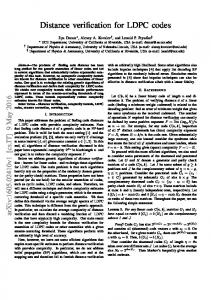
Fig. 1. Parity check Matrix for a (3,6)-regular QC-LDPC code. There are 18 circulant permutation matrices (or CPMs) marked 1, 2, 4, 8, 16, 32, 3, 6, 12 . . . 80, 160. The number denotes the offset for the CPM. For example, the circulant marked labeled 3 is shown in more detail in (b). Each circulant is a 256 256 matrix. The offset is the position of the nonzero entry in the first row of the circulant. (a) A (3,6)-regular QC-LDPC code ( = 256). (b) A = 256, offset 1 = 3. CPM with
2
m
m
for , where the operations in the sum are modulo-2 operations. Each sum is called a check-sum (check constraint). Often an LDPC code is represented graphically by a bipartite graph which consists of two disjoint sets of nodes. Nodes in one set represent the code bits and are called variable nodes (VNs), and the nodes in the other set represent the check-sums that the code bits must satisfy and are called check nodes (CNs). and the CNs from 0 to . The Label the VNs from 0 to th CN is connected to the th VN by an edge if and only if . The VNs connected to the th CN simply correspond to the code bits that are contained in the th check-sum. The CNs connected to the th VN simply correspond to the check sums that contain the th VN. In terms of encoding and decoding implementation, the most advantageous structure of an LDPC code is the QC structure. Commonly, in most of the proposed constructions of QC-LDPC codes, the parity-check matrix of a QC-LDPC code is given as array (or block) of circulants or circulant permutation a matrices (CPMs) and/or zero matrices of the same size, say , as follows:
.. .
.. .
..
.
.. .
(2)
is a matrix over GF(2). The QC-LDPC Then and code given by the null space of the matrix has length . Many standard codes for communication rate at least systems are QC-LDPC codes. Fig. 1(a) shows the code structure of a (3,6) regular maQC-LDPC codes. We denote this code as . The trix has 3 block rows and 6 block columns for a total of 18 circulant permutation matrices. Each circulant permutation matrix (CPM) is 256 256 with a certain offset, which denotes the position of the nonzero entry in the first row of the matrix. Details of a CPM with offset equal to 3 is shown in Fig. 1(b).
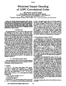
Fig. 2. Partially parallel decoder architecture for (3,6)-regular QC-LDPC codes 6) denotes the th IMEM, = 256, adapted from [9], I (0 with E (0 3 0 6) denotes the EMEM on the th row and on the th column.