Advanced Materials Research Vol. 979 (2014) pp 50-53 © (2014) Trans Tech Publications, Switzerland doi:10.4028/www.scientific.net/AMR.979.50
Baseline Popping Detection and Correction Algorithms for Perpendicular Magnetic Recording System Piya Kovintavewat1 and Santi Koonkarnkhai2 Data Storage Technology Research Center, Nakhon Pathom Rajabhat University, Thailand 1
2
[email protected],
[email protected]
Keywords: BLP detection and correction, head instability, perpendicular magnetic recording.
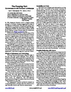
Abstract. Hard disk drives (HDDs) employ the magneto-resistive (MR) head to sense the change in magnetic flux via the transitions of magnetization pattern, resulting in a readback signal. Thus, head instability plays an important role on the reliability of HDDs because it can deteriorate the system performance considerably. Baseline popping (BLP) is one of the crucial problems caused by the head instability, whose effect can distort the readback signal to the extent of causing a sector read failure. This paper proposes three BLP detection and correction algorithms for a perpendicular magnetic recording (PMR) system. Specifically, to suppress the BLP effect experienced in the readback signal, the first algorithm is based on an averaging filter and a threshold detector; the second one relies on the estimated BLP signal obtained from a linear curve fitting technique; and finally the third one uses two sequence detectors running in parallel. Experimental results indicate that the third algorithm performs better than the other schemes because it can detect and correct the BLP better than the others, especially when the peak BLP amplitude is large. Introduction Current HDDs are based on the PMR technology, which employ the MR head to read the changes in magnetic flux, resulting in a readback signal. Thus, the read/write head plays a significant role on the quality of the readback signal, especially at high areal densities (ADs). Consequently, the head instability is one of major problems to determine the reliability of HDDs because it can considerably degrade the HDD performance. In practice, the head instability leads to many problems, including BLP, writer induced instability, spiking noise, and random telegraph noise [1-2]. Typically, the BLP is a low frequency signal. Unlike the thermal asperity (TA) [3], the BLP signal has a short rise time and a short decay time [1], and its peak amplitude is less than 1.5 times the peak of the normal readback signal. Generally, the average value of the normal readback signal is zero, while that of the BLP-affected readback signal is not, because the BLP causes a shift in the baseline of the readback signal. Hence, the BLP effect can cause an error burst in data detection, which could exceed the correction capability of error-correction codes, thus resulting in a sector read failure. It should be noted that the severity of the BLP effect relies on the BLP duration and its peak amplitude. Consequently, a method to mitigate the BLP effect is crucial, especially at high ADs. Many works have studied the BLP effect. For example, Chen et al. [1] presented a BLP detection method based on an averaging filter and a threshold detector. Ottesen et al. [3] used a bandpass filter to find the envelope of the readback signal and sent it to a threshold detector to determine the BLP. Finally, Kovintavewat et al. [4] introduced a novel BLP detection method, where the received signal is first adjusted before feeding it to the averaging filter and the threshold detector. However, no BLP correction algorithm has been proposed in the literature. In this paper, we present three BLP detection and correction algorithms to combat the BLP effect in a PMR system. Channel Model The PMR channel model with the BLP suppression block is illustrated in Fig. 1, where H(D) = ∑k hkDk = 1 + 2D + D2 is a PR2 channel [8], where hk is the kth channel coefficient and D is a unit delay operator. The BLP-affected readback signal, p(t), can then be written as
All rights reserved. No part of contents of this paper may be reproduced or transmitted in any form or by any means without the written permission of TTP, www.ttp.net. (ID: 202.29.10.6-17/06/14,12:48:57)
Advanced Materials Research Vol. 979
51
A0
t
Tr
aˆ k (a)
Tf
(b)
Fig. 1. (a) A channel model with the BLP detection and correction algorithm and (b) a BLP signal.
p ( t ) = ∑ k rk s ( t − kT ) + n ( t ) + u ( t ) ,
(1)
where rk = ak∗hk ∈{0,±2,±4} is a noiseless channel output, ak ∈{±1} is a data input sequence with bit period T, ∗ is a convolution operator, s(t) = sin(πt/T)/(πt/T) is an ideal zero-excess bandwidth Nyquist pulse, n(t) is an additive white Gaussian noise (AWGN) with two-sided power spectral density N0/2, and u(t) is a BLP signal. In practice, the BLP signal looks similar to the TA signal [5] but it has a short decay time and small peak amplitude, which can be modeled as [4] 0 ≤ t ≤ Tr A0t / Tr , , u (t ) = A0 exp ( − ( t − Tr ) / Td ) , Tr < t ≤ T f
(2)
where A0 = α Ʃk |hk| is a peak BLP amplitude, α ≥ 0 is a peak factor, Tf is a BLP duration, Tr is a rise time, and Td is a decay constant depending on a tail BLP amplitude A1. In this paper, we assume that A1 is 0.1 the peak of the normal readback signal corresponding to Tf = Tr – ln(A1/A0)Td, where ln(x) is a natural logarithm of x. At the receiver, the readback signal p(t) is filtered by an ideal lowpass filter (LPF), whose impulse response is s(t)/T, to eliminate the out-of-band noise. The filtered signal y(t) is then sampled at time kT, assuming perfect synchronization. The sampled output yk is passed to the BLP detection and correction block to alleviate the BLP effect before feeding into the Viterbi detector (VD) to determine the most likely data input sequence, aˆk .
BLP Detection and Correction Algorithms This paper introduces three BLP detection and correction algorithms as follows.
Algorithm 1. The first BLP detection and correction algorithm denoted as “Method 1” is simple, which makes use of an averaging filter and a threshold detector. Specifically, we find the average value of the readback signal, qk, according to qk =
1 k +β y , L ∑ i =k − β i
(3)
where yi is the ith sample of the readback signal, L = 2β + 1 is the window length for computing qk, and β is a positive integer. Then, a sequence qk is fed to a threshold detector to determine the presence of BLP. Basically, the BLP is detected if qk > m1, where m1 > 0 is a threshold value. After the BLP is detected, the BLP detection operation is disable, and the BLP correction operation is activated for a duration of Tf so as to alleviate the BLP effect. Hence, the readback signal after compensating for the BLP distortion is given by zk = yk – qk if the BLP is present; otherwise, zk = yk. Eventually, the corrected BLP sequence zk is fed to the VD for data detection.
52
Applied Physics and Material Science
G(D)
yk
Viterbi detector [ target = H(D)G(D) ]
zk
aˆk
BLP detection & location
Viterbi detector [ target = H(D) ]
vk
Fig. 2. The BLP detection and correction algorithm for Method 3.
Algorithm 2. To improve the performance of Method 1, we propose the “Method 2.” Here, we employs the BLP detection method presented in [4], which adjusts the readback sample yk according to dk = Σk|hk|, when yk < Σk|hk|; otherwise, dk = yk, where ∑k|hk| is the peak amplitude of {rk}, and |x| is an absolute value of x. Next, the adjusted sequence dk is sent to an averaging filter with a window length of L bits to obtain an averaged sequence qk according to (3). Hence, the averaged sequence qk is fed to a peak detector with the threshold values of m2 > 0 and m3 > 0 to determine the BLP location. Specifically, the starting point of the BLP event is detected if qk > m2 for three consecutive samples so as to make it more robust to a false alarm, whereas the ending point of the BLP event is obtained when qj < m3, where j > k and m3 < m2. In general, the BLP correction is performed by bringing the baseline of the BLP-affected readback signal back to zero. Assuming that the rise time is very small and the decay time is linear decay, the BLP signal can then be reconstructed from the samples {qk} and the BLP location, based on a linear least-squares fitting technique [5]. Finally, the corrected readback signal is obtained by subtracting the reconstructed BLP signal from the BLP-affected readback signal. Algorithm 3. Similar to [6], “Method 3” employs the two VDs running in parallel as depicted in Fig. 2, i.e., one for the H(D) target and the other for the G(D)H(D) target, where G(D) = 1 – D2 is a bandpass filter [7] for eliminating the BLP effect. Practically, the VD for the H(D) target yields low bit-error rate (BER) in the absence of the BLP, whereas that for the G(D)H(D) target offers low BER in the presence of the BLP. Consequently, the overall detected bit stream aˆk is chosen from the output of these two VDs depending on whether or not the BLP is present, i.e.,
z , if BLP is present aˆk = k . vk , if BLP is absent
(4)
To obtain the BLP location, Method 3 employs the BLP detection algorithm used in Method 1 and Method 2, which will be referred to as “Method 3-1” and “Method 3-2,” respectively.
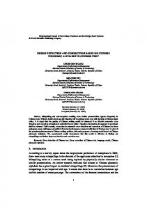
Experimental Results Consider the channel model in Fig. 1(a), where every 4096-bit data sector is corrupted by one BLP event occurred randomly with the tail BLP amplitude of A1 = 0.1∑k| hk |. Here, we define a per-bit signal-to-noise ratio as Eb / N0 = 10log10(∑k| hk |2/N0) in dB, where Eb is the energy per bit. The BER is computed based on a minimum number of 5000 data sectors and 1000 error bits, and call that number as “BER given BLP.” For the PR2 channel, Method 1 uses L = 251 bits and m1 = 1.14, and Method 2 employs L = 101 bits, m2 = 4.12, and m3 = 4.015 [4], where all parameters are designed by maximizing the percentage of detection and minimizing the percentage of false alarm at Eb/N0 = 12 dB, where the uncoded system without a BLP event yields BER of 10-5 [4]. Fig. 3(a) illustrates the BER performance with different schemes, where the performance of the system without BLP is referred to as “Without BLP.” Without BLP detection and correction, the system performance is unacceptable, denoted as “With BLP.” It is apparent that Method 3-2 performs the best, followed by Method 3-1, Method 2, and Method1. This might be because Method 3-2 can
Advanced Materials Research Vol. 979
10
10
10
-1
with BLP Method 1 Method 2 Method 3-1 Method 3-2
-2
-3
BER given BLP
BER given BLP
10
53
without BLP with BLP Method 1 Method 2 Method 3-1 Method 3-2
-4
7
8
9 10 (a) Eb/N0 (dB)
11
12
10
10
-2
-3
0.1
0.15
0.2
0.25 0.3 0.35 peak factor (α)
0.4
0.45
0.5
(b)
Fig. 3. (a) BER performance of different schemes, and (b) BER performance as a function of peak factors.
efficiently detect the BLP location and suppress the BLP effect embedded in the readback signal. We also plot the BER performance as a function of peak BLP amplitudes as shown in Fig. 3(b), at Eb/N0 = 10.7 dB when the system without BLP provides the BER of 10-4. Again, Method 3-2 yields better performance than other schemes, especially when the peak BLP amplitude is large. This is because Method 3-2 can detect and correct the BLP better than the other schemes when the peak factor is large.
Summary A baseline popping (BLP) is one of the major problems caused by head instability, whose effect can distort the readback signal to the extent of causing a sector read failure. Without BLP detection and correction algorithms, the system performance can be unacceptable. This paper proposed three algorithms to detect and correct the BLP effect embedded in the readback signal for PMR systems. The first algorithm is simple, which makes use of an averaging filter and a threshold detector. The second one reconstructs the BLP signal using a curve fitting technique, where the corrected readback signal is obtained by subtracting the reconstructed BLP signal from the BLP-affected readback signal. Finally, the third algorithm employs two VDs working concurrently, where the overall detected bit is selected from these two VDs, depending on if the BLP is detected. From simulations, we found that Method 3-2 performs the best because it can detect and correct the BLP better than the others, especially when the peak BLP amplitude is large.
References [1] L. Chen, E. Chen, J. Giusti, J. F. de-Castro, D. Saunders, Micro-magnetic and electric analysis on MR head baseline popping and instabilities. IEEE Trans. Magn. 37 (2001) 1343-1345. [2] E. Chen, D. Saunders, J. F. de-Castro, Junction edge instability in simple spin valve recording heads. IEEE Trans. Magn. 36 (2000) 2581-2583. [3] H. H. Ottesen, G. J. Smith, US Patent 6,671,111 B2. (2003) [4] P. Kovintavewat, S. Koonkarnkhai, A. Suvichakorn, Head instability detection for testing process in perpendicular magnetic recording system. Advanced Materials Research 770 (2013) 319-322. [5] P. Kovintavewat, S. Koonkarnkhai, Joint TA suppression and turbo equalization for coded partial response channel. IEEE Trans. Magn. 46 (2010) 1393-1396. [6] V. Dorfman, J. K. Wolf, A method for reducing the effect of thermal asperities. IEEE J. Selected Areas in Commun.19 (2001) 662-667. [7] S. Koonkarnkhai, P. Kovintavewat, P. Keeratiwintakorn, The effect of bandpass filters for thermal asperity suppression in perpendicular magnetic recording systems. ECTI Trans. Electrical Engineering, Electronics, and Communications 8 (2010) 93-98.