Battery Power System with Arrayed Battery Power Modules Chin-Sien Moo*, Jhen-Yu Jian*, Tsung-Hsi Wu*, Li-Ren Yu*, Chih-Chiang Hua** * Dept. of E.E., National Sun Yat-sen University, Kaohsiung, Taiwan ** Dept. of E.E., National Yunlin University of Science & Technology, Yunlin, Taiwan
[email protected],
[email protected],
[email protected],
[email protected],
[email protected] Abstract A battery power system configured by arrayed battery power modules (BPMs) is presented. Each BPM consists of a battery pack equipped with an associated bi-directional power electronic converter for charging and discharging. The number of BPMs in the array is schemed to cope with the required output voltage, current, power as well as sustainable energy. All BPMs in the configuration are mutually interactive to each other and have to be operated collaboratively with the others, but allowed to be controlled individually, facilitating the maintenance, protection, and the management of the battery power system. Keywords: Battery, power electronic converter, battery power module (BPM), BPM array.
I.
INTRODUCTION
Conventionally, battery cells are connected in series to obtain a higher voltage and in parallel to deliver a larger current. For large scale battery power systems such as those in electric vehicles (EVs) and power storage of renewable energy, they are arrayed to form battery power banks for handling higher power and energy [1, 2]. A battery power bank with a great number of cells, however, inevitably encounters the problems of unequal charging and discharging, which will limit the available power and energy capacities and cause degradation of battery cells [3-7]. This problem is partially solved by strictly sorting the produced cells on their key parameters, such as voltage, capacity, and internal impedance. Although the similarity and consistency of the selected cells in the bank are assured by manufacturers, a charge equalization circuit is needed to avoid charge imbalance from slight discrepancy among cells that will be magnified during cyclic charging and discharging [8-13]. Both battery sorting and charge equalization increase an extra amount in the production cost. Moreover, the charge equalizing process will bring about energy loss leading to deficiency in energy utilization of the battery cells. To deal with the problematic imbalance in the battery bank, the battery power system can be reconfigured by introducing the concept of the battery power module (BPM) [14]. In the configuration, a power bank consists of a number of BPMs in array connection. Each BPM consists of a battery set with an associated output converter. All BPMs collaborate on supplying the load power but can be controlled in accordance with the individual status.
II.
BATTERY POWER MODULES
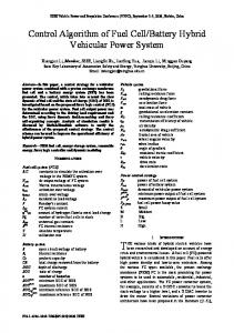
Ideally, a BPM is formed by a single battery cell with an associated power conversion circuit so that the problem of charge equalization will not be crucial. For the time being, however, such an arrangement is uncompetitive to the conventional application with battery banks since power conversion efficiency can be impracticably low due to low cell voltages. To retain high conversion efficiency, a battery set can be a single-packed battery or a battery bank with an adequate number of batteries connected in series [15-17]. This compromise needs a small-scale battery management system (BMS) with charge equalization for the serial batteries [18]. The power conversion circuit can be a dc-to-dc converter to step up/down the output voltage to the required level for the load, or a dc-to-ac inverter to convert the virtual dc voltage from the battery set into an ac power. The BPM can provide the regulation of voltage, current or power at the output port. Furthermore, the BPM is capable of recovering the battery power from a charger, which may draw power from solar cells, wind generators, or utility mains when a bi-directional power converter is used. Fig. 1 shows the BPMs equipped with three basic bidirectional dc-to-dc converters, including the buck/boost, boost/buck, and bi-directional buck-boost typed BPMs, which are named from the view point of the battery side. With a bidirectional converter, the BPM can perform both charging and discharging. In the bidirectional BPMs, the freewheeling diodes are replaced by power MOSFETs as the active power switches, which can in turn perform synchronous rectification to improve the conversion efficiency. III.
SERIAL CONNECTION OF BPMS
For high voltage applications, a number of BPMs can be connected in series to meet the load requirements. Fig. 2 shows an exemplar battery power source with serial configuration formed by n BPMs with associated bidirectional boost/buck converters. The load voltage Vout is the sum of the output voltages.
VO1 + VO 2 + " + VOn = Vout
(1)
where VOi denotes the average output voltage of the ith BPM.
IV.
PARALLEL CONNECTION OF BPMS
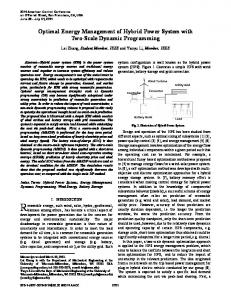
To provide more power and energy, BPMs are operated in parallel. An exemplar parallel configuration shown in Fig. 3 is formed by n BPMs with bidirectional boost/buck converters. With parallel configuration, the output voltages of all BPMs are identical to each other and equal to the load voltage Vout.
(a) Buck/Boost BPM
VO1 = VO 2 = " = VOn = Vout
(b) Boost/Buck BPM
(c) Bidirectional buck-boost BPM Fig. 1 BPMs with bidirectional converters
Theoretically, BPMs’ output voltages are allowed to be adjusted individually but have to contribute collaboratively to the required high voltage by the load. In case that all boost/buck converters are operated at the continuous conduction mode (CCM), the relationship among the output voltages can be expressed as VO1 : VO 2 : " : VOn =
V VB1 V : B 2 : " : Bn 1 − d1 1 − d 2 1 − dn
(2)
Fig. 2 Boost/buck BPMs connected in series
where VBi and di denotes the battery voltage and the duty-ratio of the power converter in the ith BPM, respectively. Since all BPMs are connected in series, the output currents of all BPMs are identical to each other. The average current is equal to the average output current Iout flowing to the load.
I O1 = I O 2 = " = I On = I out
(3) th
where IOi is the average output current of the i BPM. On the other hand, the input currents of BPMs can be different from others. These currents are dependent on the battery voltages and can be regulated by the power conversion circuits, meaning that the currents drawn from battery sets are controllable. The ratios among the battery currents can be expressed as I B1 : I B 2 : " : I Bn =
1 1 1 : :" : 1 − d1 1 − d 2 1 − dn
(4)
Equations (2) and (4) indicate that the currents drawn from batteries can be controlled in accordance with terminal voltages of the battery sets.
Fig. 3 Boost/buck BPMs connected in parallel
(5)
Contrariwise, the output currents from BPMs can be different to each other. The average load current Iout is the sum of the average output currents from BPMs.
I O1 + I O 2 + " + I On = I out
(6)
In other words, the required load current is contributed by all BPMs in operation. For the BPMs with boost conversion operating at CCM, the battery currents in BPMs can be regulated by controlling the duty-ratios. I B1 : I B 2 : " : I Bk : ⋅⋅⋅ : I Bn ⎛ 1 ⎞ ⎛ 1 =⎜ ⎟:⎜ ⎝ 1 − d1 ⎠ ⎝ 1 − d 2
V.
⎛ 1 ⎞ ⎟ :" : ⎜ ⎠ ⎝ 1 − dk
⎞ ⎛ 1 ⎞ ⎟ :" : ⎜ ⎟ ⎠ ⎝ 1 − dn ⎠
(7)
ARRAY CONFIGURATIONS OF BPMS
For the load which requires high voltage and current at the same time, BPMs can be connected in an array, which is in series to boost up the output voltage and in parallel to supply sufficient power to the load. Figs. 4 and 5 show two exemplar battery power systems. A number of BPMs are arrayed into an n by m matrix. Both power banks are composed of two matrices. To minimize the maximum voltage referenced to the ground, the power system is symmetrically arranged into a positive group and a negative group. Each group consists of an n by m matrix.
Fig. 4 BPMs connected first in series and then in parallel
In Fig. 4, a group of BPMs are first connected in series to cope with the required high load voltage and then in parallel to supply a sufficient power, respectively. The BPMs in a queue are connected in series. Each BPM-queue consists of n BPMs to meet the load voltage requirement. To supply a high output current, m BPM-queues are connected in parallel. This three-wire configuration can provide positive and negative voltages of Vdc, and in addition a high voltage of 2Vdc. The configuration in Fig. 5 consists of the same number BPMs as those in Fig. 4. The BPMs in a row are connected in parallel forming a BPM-row. Each BPM-row is composed of m BPM-rows to cope with the required load current, while the terminal voltage is aggregated by a number of BPM-rows connected in series. In practical applications with such a configuration, various dc voltages are available for different loads and the sustaining time of the power bank can be prolonged by increasing the number of BPMs in BPM-rows. With step-up/down converters, the number of batteries used in such a battery power bank is not restricted by the load voltage and current, but can be designed to fit the requirements of the maximum power and sustaining time. Furthermore, the batteries for BPMs in a power bank are not restricted to a same type. With the benefit of virtually independent operation, the techniques of charge equalization, state-of-charge (SOC) estimation, state-of-health (SOH) evaluation and failure detection can be easily implemented on the BPM array. VI.
BALANCED CHARGING AND DISCHARGING
When bidirectional converters are adopted in BPMs, the BPM arrays can perform both charging and discharging. The
Fig. 5 BPMs connected first in parallel and then in series
configuration allows the BPMs be individually operated so that the charging/discharging currents flowing into and out from batteries can be coordinated to provide a full amount of
the charge/load currents. In other words, the operation of BPMs can be scheduled to fulfill the system requirements. With associated power converters, the fully charged and exhaustedly discharged batteries as well as the damaged ones can be isolated by stopping the associated power converters or switching off the additional mechanical switches. This means that charge equalization is not the crucial issue in such a battery power system. On the other hand, it is more important to store more energy during the charging process. The battery power source can sustain longer when all BPMs are in order to collaboratively share the load current, meaning that the battery power can be efficiently utilized with balanced discharging. However, battery charge equalization with full power capacity of the BPMs can be easily accomplished for both directions since the charging and discharging currents can be programmed in accordance with the SOCs of batteries. For balanced discharging, the batteries with higher SOCs are drawn more currents during operation. In practice, the battery with a larger SOC is subjected to a slightly higher voltage. Therefore, a higher duty-ratio is needed to draw a larger current from the battery.
Y = n−
Vo ⎛ d mean ⎞ ⎜ VB ⋅ ⎟ 1 − d mean ⎠ ⎝
(9)
When the array connection of boost/buck-typed BPMs in Fig.4 is adopted, the fault BPMs can be blocked by simply removing the corresponding gate control signals, as illustrated by Fig. 7. When some BPMs have been removed, the power bank supplies the system continuously with a reduced load power.
VII. FAULT TOLERANCE In the power bank, all BPMs are operated cooperatively. With such a configuration, those BPMs with completely exhausted or damaged batteries can be isolated or removed from the battery power bank without interrupting the system operation. Fig. 6 illustrates an exemplar case of a serial configuration of boost/buck-typed BPMs with a defective battery set in BPM 2. An extra switch has to be added to isolate the defective battery set. The operation of the associated boost/buck converter can be stopped by removing the gate signal of the active power switch. At the beginning, the output filter capacitor is discharged since it is connected in series with the other BPMs. The capacitor voltage declines and
Fig. 6 Fault tolerance for serial BPMs with boost/buck conversion
eventually becomes a negative to forward bias the parasitic diode of M2 and the intrinsic body diode of the power MOSFET S2, providing a bypass current path. Unfortunately, the battery set will be short-circuited causing a danger to the system. In this case, an extra mechanic switch has to be added to isolate the battery set from the current path. To find the maximum fault tolerance, the converters are assumed to be operated in the CCM. The output voltage, Vo, of the serial BPMs can be regulated by controlling the duty-ratios of the boost/buck converters in a range of the duty-ratio from the minimum, dmin, to the maximum, dmax. In general, the rated output voltage of n serial BPMs is designated as the sum of the converter output voltages at the average duty ratio, dmean, under the nominal battery set voltage, V B.
⎛ d ⎞ Vo = ⎜ mean ⋅ VB ⎟ ⋅ n ⎝ 1 - d mean ⎠
(8)
Then, the allowable shut-down modules, Y, can be calculated as
Fig. 7 Fault tolerance for parallel BPMs with boost/buck conversion
VIII. CONCLUSIONS A novel battery power system configured by arrayed battery power modules, which are formed battery sets equipped with dc-to-dc converters, has been proposed to meet the large scale power requirement. The BPMs in the battery power system are substantially operated individually so that bidirectional charge equalization with full-power can be accomplished. In addition to the excellent balanced charging and discharging performances as well as an exceptional fault tolerant capability, the power bank with arrayed BPMs owns following advantages: (1) With associated converters, the output voltage can be well regulated. (2) The stored energy in the batteries can be utilized more efficiently since the batteries discharging currents can be individually profiled. (3) The SOCs of batteries can be more accurately estimated through on-line monitoring. (4) The modular design simplifies maintenance, enhances operating functions, and provides the flexibility in extending the battery power of the system. (5) Extensive management algorithms can be realized. These advantages, however, are at expense of a higher installation cost and lower overall power conversion efficiency if a same number of batteries are used in the battery power system. The installation cost of the battery power system with BPMs is apparently higher than that of the conventionally used battery power, which is without any converter or with fewer converters. To overweigh this shortcoming, a battery power system should be designed with an appropriate number of BPMs with associated power electronic converters with optimal power rating, by which, the discharging currents can be coordinated in accordance with the load requirements and the battery conditions, and, the number of batteries can thus be reduced. Moreover, the cost of maintenance is reduced substantially by the diminution of battery failure and longer the battery life cycles. REFERENCES [1]
[2]
A. M. Sharaf, E. Ozkop, and I. H. Altas, “A Hybrid Photovoltaic PV Array-Battery Powered EV-PMDC Drive Scheme,” in EPC 2007, pp. 37-43, Oct. 2007. J. Crowell, “Battery Arrays, Rechargable Li-Ion Battery Power Sources for Marine Applications,” in OCEANS 2005, pp. 46-51, Sep. 2005.
[3]
N. H. Kutkut, H. L. N. Wiegman, D M. Divan, and D. W. Novotny, “Design Considerations for Charge Equalization of an Electric Vehicle Battery System,” IEEE Transactions on IA, vol. 35, no. 1, pp. 28-35, Jan./Feb. 1999
[4]
M. Dubarry, N. Vuillaume, and B.-Y. Liaw, “From Single Cell Model to Battery Pack Simulation for Li-Ion Batteries,” in J. Power Sources, vol. 186, no. 2, pp. 500–507, Jan. 2009.
[5]
D. Brunner, A. K. Prasad, S. G. Advani, and B. W. Peticolas, “A Robust Cell Voltage Monitoring System for Analysis and Diagnosis of Fuel Cell or Battery Systems,” in J. Power Sources, vol. 195, no. 24, pp. 8006–8012, Dec.2010. J. Kim, J. Shin, C. Chun, and B. H. Cho, “Stable Configuration of A Li-Ion Series Battery Pack Based on A Screening Process for Improved Voltage/SOC Balancing,” IEEE Transactions on PE, vol. 27, no. 1, pp. 411–424, Jan.2012. M. Bradgard, N. Soltau, S. Thomas, and R. W. De Doncker, “The balance of renewable sources and user demands in grids: power electronics for modular battery energy storage system,” IEEE Transactions on PE, vol. 25, no. 12, pp. 3049–3056, Dec. 2010. J. Chatzakis, K. Kalaitzakis, N. Voulgaris, and S. Manias, “Designing a New Generalized Battery Management System,” IEEE Transactions on IE, vol. 50, no. 5, pp. 990-999, Oct. 2003.
[6]
[7]
[8]
[9]
S. T. Hung, D. C. Hopkins, and C. R. Mosling, “Extension of Battery Life via Charge Equalization Control,” IEEE Transactions on IE, vol. 40, no. 1, pp. 96-104, Feb. 1993.
[10] W. Hong, K. S. Ng, J. H. Hu, and C. S. Moo, “Charge Equalization of Battery Power Modules in Series,” in IPEC 2010, pp. 1568-1572. June 2010. [11] J. Cao, N. Schofield, and A. Emadi, “Battery Balancing Methods: A Comprehensive Review,” in VPPC 2008, pp. 1-6, Sep. 2008. [12] A. Affanni, A. Bellini, G. Franceschini, P. Guglielmi, and C. Tassoni, “Battery Choice and Management for New-Generation Electric Vehicles,” IEEE Transactions on IE, vol. 52, pp. 1343-1349, Oct. 2005. [13] J. H. Kim, J. W. Shin, C. Y. Chun, and B. H. Cho, “Stable Configuration of a Li-Ion Series Battery Pack Based on a Screening Process for Improved Voltage/SOC Balancing,” IEEE Transactions on PE, vol. 27, no. 1, pp. 411-424, Jan. 2012. [14] C. S. Moo, K. S. Ng, and Y. C. Hsieh, “Parallel Operation of Battery Power Modules,” IEEE Transactions on EC, vol. 23, no. 2, pp. 701-707, Jun. 2008. [15] C. S. Moo, Y. C. Hsieh, I. S. Tsai, and J. C. Cheng, “Dynamic Charge Equalization for Series-Connected Batteries,” IEEE Transactions on EPA, vol. 150, no. 5, pp. 501-505, Sep. 2003. [16] Y. C. Hsieh, S. P. Chou, and C. S. Moo, “Balanced Discharge for Series-Connected Batteries,” in PESC 2004, pp. 2697-2702, June 2004. [17] C. S. Moo, K. S. Ng, and J. S. Hu, “Operation of Battery Power Modules with Series Output,” in ICIT 2009, pp. 1-6, Feb. 2009. [18] L. Maharjan, T. Yamagishi, and H. Akagi, “Active-power control of individual converter cells for a battery energy storage system based on a multilevel cascade PWM converter,” IEEE Transactions on PE, vol. 27, no. 3, pp. 1099–1107, Mar. 2012.