Acoustics 08 Paris
Beampattern optimization for a conformal projecting array of transducers with baffle effect and mutual coupling among elements Y. Ma and Z. He Institute of Acoustic Engineering, Northwestern Polytechnical University, 710072 Xi’an, China
[email protected]
985
Acoustics 08 Paris Beampattern optimization for projecting arrays is much more challenging in comparison with receiving arrays, particularly for conformal projecting arrays. It is because the array elements have to work in resonance state for efficient projecting and the variation of radiation impedance has strong effect on the array performance. The radiation impedance for each element is determined by a lot of factors, i.e, the element position, baffle property, mutual coupling and velocity weighting vector of the array. Thus beampattern optimization for a projecting conformal array must take into account all these factors. One thing makes the topic more difficult that the mutual impedance for each element is changeable along with the weighting vector change. In this paper a global solution approach is formulated and a boundary element model combined with transducer equivalent circuits is developed. The driving voltage weighting vector is deduced through an optimization algorithm. Computer simulation together with experiments are conducted for a 14-element conformal array. The results agree well. The multiple beampatterns formed within a wide observation sector exhibit uniform beamwidth and low sidelobes. The source level for each beam is maximized in constraint of the maximum driving voltage of array elements being constant.
1
certain distance from the center in the radiated acoustic field of the transducer array with a certain impedance boundary condition baffle can be obtained using the boundary element method [8]. Assume that the vibration velocity weighting vector of the transducer array is WV ,
Introduction
In underwater acoustic projecting transducer array of active sonar and AUV, good projecting beampattern such as a low sidelobe level and high transmitting source level is always expected, thus the transmitting sound energy can be focused in the concerned direction, and the long-range object can be detected with a relatively lower transmitting sound energy. In order to achieve good system performance, the lowfrequency, high-power and broadband acoustic radiation of the transducer array is often expected [1]. In the research of the radiated acoustic field for compact transducer arrays, especially for compact conformal array, the mutual interactions among elements must be considered [2-5]. The conformal array for mobile platform is small in volume with compact elements, and the shape is the same as that of the carrier. Consequently, the interactions among elements in conformal array are definitely significant. On the other side, the radiated acoustic field of the transducer array may be greatly influenced by the baffle with a certain impedance boundary condition [4,6].
then the sound pressure in the θ direction on a certain distance from the center of the array can be calculated as follows:
p(θ ) = X(θ ) T WV
Suppose that the driving voltage weighting vector of the transducer array is WE , then the vibration velocity weighting vector of the array can be calculated using the equivalent circuit principle, which is:
WV = nZ −1 WE
(2)
where n is electromechanical transfer ratio of the transducers, and Z is the mutual impedance matrix of the array, which is:
⎡ Z m 0 + z11 ⎢ Z = ⎢ z 21 ⎢ M ⎢ ⎣ z L1
Some preliminary research work has been conducted on the influence of the baffle effect and mutual interactions among elements to the performance of the transducer array [4,7]. However, the research work only dealt with the cases of planar array, and the structure of the baffles was relatively simple and assumed to be rigid, and the radiation directivity of the arrays was not controlled. Furthermore, the calculation was all theoretical simulation, in which the validity and effectiveness had not been verified by experiment.
where
z12 L Z m 0 + z 22 L M z L2
⎤ ⎥ ⎥ ⎥ M ⎥ + z LL ⎦
z 1L z 2L
M L Z m0
(3)
z ii is the self-radiation impedance of the ith trans-
ducer, and
z ij is the mutual radiation impedance between
the ith transducer and the jth transducer, and Z m 0 is the mechanical impedance of the transducers in the array. Substituting Eq. (2) into Eq. (1) produces:
In this paper, the boundary element theory together with the optimization method is employed to calculate the driving voltage weighting vector of an underwater acoustic transducer conformal array mounted on a complicated finite baffle with a certain impedance boundary condition in order to obtain a low-sidelobe beampattern and good projecting performance. And an experiment has been conducted to verify the simulation results in an anechoic water tank.
p(θ ) = nX(θ ) T Z −1 WE
(4)
Because the maximum amplitude of the driving voltage of the transducers in the array is limited, in order to obtain a low-sidelobe projecting beampattern and a sound source level as high as possible, it needs to provide the largest pressure amplitude in the axial direction of the array when the maximum amplitude of the driving voltage weighting vectors keeps unchanged. That is, to make the maximum modulus of the driving voltage weighting vector to be the least, while producing the same amplitude of pressure in the axial direction of the array and at the same time imposing constraints on the sidelobe of the projecting beampattern. As the driving voltage weighting vector to be calculated is the normalized vector, the coefficient n in Eq. (4) can be
2 Principle of projecting beampattern optimization The response vector
(1)
X(θ ) in different directions on a 986
Acoustics 08 Paris dashed line represents that the weighting vector is calculated by the plane wave model optimization method with the sidelobe level also constrained to –20dB. Fig. 2~Fig.3 shows that the proposed method in this paper can be used to control the sidelobe of the projecting beampattern of the transducer array and obtain a lowsidelobe level. Using the proposed method, the highest sidelobe level of the beampattern is –20dB. Using the conventional beamforming method, the highest sidelobe level is -5.7dB. Using the plane wave model optimization method, the beampattern is distorted and the highest sidelobe level is -10.3dB. On the other hand, because the proposed method and the plane wave model optimization method impose constraints on the sidelobe level of the beampattern comparing with the conventional beamforming method, the maximum pressure amplitude of the mainlobe may reduce. The proposed method can provide the largest pressure amplitude in the axial direction of the transducer array when the maximum amplitude of the driving voltage weighting vectors keeps unchanged, at the same time satisfying the sidelobe constraints. Corresponding to Fig. 2, using the proposed method comparing with the conventional beamforming method, the maximum pressure amplitude does not reduce much, which is 1.67dB. It can be seen from above that the mutual interactions among elements and the baffle with a certain impedance boundary condition may greatly influence the radiated acoustic field of the conformal array. When the driving voltage weighting vector using the conventional beamforming method and the plane wave model optimization method without considering the acoustic interactions, the radiation beampattern of the
left out of account. It leads to the following optimization problem:
⎧ min( max ( WE ( j ) )) ⎪ WE j =1,L, L ⎪ T −1 ⎨ s.t. X(θ 0 ) Z WE = 1 ⎪ X(θ s ) T Z −1 WE ≤ δ s ⎪⎩ where
(5)
L is transducer number of the array. θ 0 is the
mainlobe direction,
θs
is the sidelobe direction and
δs
controls the sidelobe level of the projecting beampatern. The optimization problem (5) can be solved by means of the optimization algorithm. Then, the required driving voltage weighting vector of the transducer array is calculated. The practical driving voltage exerted on the transducers in the array is obtained by normalizing the calculated weighting vector, in which the weighting vector is divided by the maximum modulus of the vector, and then multiplied by a voltage factor which must be less than the maximum voltage that can be exerted on the transducers of the array.
3
Simulations
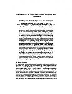
The boundary element model and mesh of the underwater acoustic transducer conformal array is shown in Fig. 1. This conformal array consists of 14 piston transducers. It is set in the middle arc line of a hemispherical baffle. Underside the baffle is the cover board. The surface of the hemispherical baffle is of rubber. The two sides of the baffle are of organic glass. The cover board is made of aluminum. The radius of the hemispherical baffle is r = 0.216 m. The radiation surface of each piston transducer is rectangular with the length a = 0.04 m, the width b = 0.04 m. The sound frequency is f = 12.5 kHz, and the wavelength is
λ = 0.12 m. The mechanical impedance of the transducers is measured, which is Z m 0 = 831 . 25 − j1698 . 8
N ⋅ s/m . Three methods are used to calculate the driving voltage weighting vector of the transducer array. The first method is the conventional beamforming method in which the weighting vector is calculated through phase compensation according to the geometrical positions of the elements by the plane wave model without considering the baffle effect and mutual interactions among elements [9]. The second method is the plane wave model optimization method in which the weighting vector is calculated by the plane wave model and the optimization method with the same criteria as proposed in this paper also without considering the acoustic interactions. The third method is the method proposed in this paper, which uses Eq. (5) to calculate the weighting vector of the array. Fig. 2~Fig.3 are respectively the radiated sound pressure amplitude and directivity of the 14-element conformal array calculated by the boundary element method when the beam scan angle is 75°. The maximum pressure amplitude has been normalized to 1. The solid line represents that the weighting vector is calculated by the proposed method with the sidelobe level constrained to –20dB. The dotted line represents that the weighting vector is calculated by the conventional beamforming method with the plane wave model. The
Fig. 1. Boundary element model of the transducer conformal array.
Fig. 2. The radiated pressure amplitude of the array when the beam scan angle is 75°.
987
Acoustics 08 Paris simulation results. It verifies that the proposed method is valid and practical.
Fig. 3. The radiation directivity of the array when the beam scan angle is 75° . Fig. 4. The measured radiated pressure amplitude of the array when the beam scan angle is 75° .
array may be distorted with high sidelobe level. However, the proposed method can successfully take into account the acoustic interactions, and with reasonable optimization, a low-sidelobe beampattern and good projecting performance can be obtained.
4
Experimental results
An experiment has been conducted to measure the radiated acoustic pressure directivity of the conformal array in an anechoic water tank. The working frequency is f = 12.5 kHz. The maximum driving voltage exerted on the transducer array is 4V, that is, the normalized driving voltage weighting vector calculated by Eq. (5) is multiplied by the voltage factor 4V. Fig. 4~Fig. 5 are respectively the measured radiated sound pressure amplitude and directivity of the 14-element conformal array when the beam scan angle is 75°. The maximum pressure amplitude has been normalized to 1. The solid line, dotted line and dashed line represent the same meanings as those in Section 3. From Fig. 4~Fig. 5, it can be found that the results measured in the experiment are consistent with the simulation results in Section 3, which reveals that the proposed method can calculate the driving voltage weighting vector of the conformal array to obtain a low-sidelobe projecting beampattern. Using the proposed method, the highest sidelobe level of the measured beampattern is –15.3dB when the beam scan angle is 75°. Using the conventional beamforming method, the highest sidelobe level of the measured beampattern is –5.9dB. And using the plane wave model optimization method, the highest sidelobe level of the measured beampattern is –9.8dB. It is shown that the highest sidelobe level reduce much using the propose method comparing with the other two. There are some differences between the experimental results and the theoretical simulation results caused by the modeling error, calculation error and experiment error. On the other hand, just as the same in simulation computation, the proposed method can provide the largest pressure amplitude in the axial direction of the transducer array when the maximum amplitude of the driving voltage weighting vectors keeps unchanged, and at the same time satisfying the sidelobe constraints. Corresponding to Fig. 4, by use of the proposed method comparing with the conventional beamforming method, the maximum pressure amplitude does not reduce much, which is 1.72dB. It can be seen that the results measured in the experiment are greatly consistent with the
Fig. 5. The measured radiation directivity of the array when the beam scan angle is 75° .
5
Conclusions
In this paper, the boundary element model together with the optimization method is used to calculate the driving voltage weighting vector of a conformal array to obtain a lowsidelobe beampattern and good projecting performance. The computer simulation reveals that in the transducer conformal array the mutual interactions among elements and the baffle with a certain impedance boundary condition may greatly influence the radiated acoustic field of the array. When the driving voltage weighting vector of the array is calculated by the conventional beamforming method and the plane wave model optimization method without considering the acoustic interactions, the radiation beampattern of the array may be distorted and the sidelobe level may be very high. The proposed method in this paper can successfully take into account the acoustic interactions and obtain a low-sidelobe beampattern and at the same time provide the largest pressure amplitude in the axial direction of the array when the maximum amplitude of the driving voltage weighting vectors keeps unchanged. An experiment has been conducted to measure the radiated acoustic pressure directivity of the conformal array in an anechoic water tank. The experimental results demonstrate that the proposed method is valid and practical. Further research may seek better calculation model of the radiated acoustic
988
Acoustics 08 Paris field which can more precisely approximate the practical case of the transducer array.
Acknowledgments This work was supported by the National Natural Science Foundation of China under Grant No. 10734030.
References [1] Jean-Noel Decarpigny., “The design of low-frequency underwater acoustic projectors: present status and future trends” , IEEE J. Oceanic Eng. 16,107-122 (1991). [2] Lawrence E. Kinsler, Fundamentals of acoustics (Wiley, New York, 2000), pp.390-406. [3] David L. Carson, “ Diagosis and cure of erratic velocity distribution in sonar projector arrays”, J.Acoust.Soc. Am. 34,1191-1195 (1962). [4] Christan Audoly, “Some aspects of acoustic interacttions in sonar transducer arrays”, J.Acoust.Soc.Am. 89, 1428-1433 (1991). [5] Jongkil Lee,Inchang Seo, “Radiation power estimation for sonar transducer arrays considering acoustic interacttion. Sensors and Actuators A 90,1-6(2001). [6] Harry A. Schenck, “Improved integral formulation for acoustic radiation problems”, J.Acoust.Soc.Am. 44,4158 (1968). [7] Tomoki Yokoyama, “Mitsuru Henmi. Effects of mutual interactions on a phased transducer array”, Jpn. J. Appl. Phys 37,3166-3171 (1998). [8] He Zhengyao, Ma Yuanliang, “Calculation of baffle effect and mutual interaction between elements for an underwater acoustic conformal array with application to the optimization of projecting beampattern”, Chinese Science Bulletin 52, 2584-2591 (2007). [9] Wolfgang H. Kummer, “Basic array theory”, Proc. IEEE 80, 127-139 (1992).
989