information does not help with rotational mobility. In contrast .... software interface for instant RSSI, e.g. MAX 2829 used in ..... A video demo is available at [18] ... BeamSwitch Rotating Speed (°/s). Music. Video. FTP. R. Desk. 0. 5. 10. 15. 20. 25.
BeamSwitch: System Solution for Energy-Efficient Directional Communication on Mobile Devices Technical Report 0616-09 Hasan Dumanli, Ardalan Amiri Sani, Lin Zhong, and Ashutosh Sabharwal Department of Electrical & Computer Engineering, Rice University, Houston, TX 77005 Abstract: Directional communication has the potential to improve the energy efficiency of wireless communication without sacrificing its quality. We present a system solution, BeamSwitch, for directional communication on mobile devices. BeamSwitch employs a special multi-antenna system that consists of multiple identical directional antennas1, or beams, a single regular omni-directional antenna, and a single RF chain. It uses one of the directional beams for transmitting data frames and receiving their acknowledgements and the regular antenna for all other transceiving. BeamSwitch tracks the signal strength of incoming frames and selects the right beam for data transmission. We report an extensive evaluation of BeamSwitch including both measurements with a prototype with three beams and Qualnet-based simulation. Our evaluation shows that BeamSwitch with three 6 dBi directional antennas can improve the energy efficiency of a commercial 802.11 network interface card (NIC) by up to 20% and simultaneously provide better or close communication quality. BeamSwitch achieves this under diverse radio propagation environments and extreme mobility (up to 360° per second direction change).
1. Introduction Current mobile devices radiate power into all directions for wireless transmission, which can be wasteful when they are communicating with a single party. Such directional waste can be alleviated by focusing radiation along the right direction, or directional transmission. With directional transmission, a lower transmission power can be potentially employed to achieve the same receiver signal strength and therefore improve the energy efficiency of transmission. While extensive research has been devoted to directional communication, few have studied it for mobile devices, which can not only move but also rotate. Our driving vision is directional communication on mobile devices that not only minimizes directional waste but also suppresses interference between devices. In this work, we provide a system solution for directional communication for mobile devices in the infrastructure mode, called BeamSwitch. We intend BeamSwitch to be implemented with the wireless network interface card (WNIC), 1
It is very important to note that “antenna” is often used to refer to the whole RF system, including antennas and RF chains, e.g. smart antenna and phase array antenna. In this work, we use “antenna” to refer to the actual antenna only.
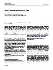
which usually implements the MAC layer and below of the network protocol stacks. Figure 1 illustrates the key components of BeamSwitch and how they interact with the network protocol stack in the WNIC. BeamSwitch addresses two key technical challenges toward improving energy efficiency. First, popular hardware realization of directional communication, including phasedarray antenna systems and sectorization, are expensive in terms of power, hardware, and form factor. In contrast, BeamSwitch employs a special multi-antenna system that consists of multiple identical directional antennas, or beams, and a single regular omni antenna, all driven by a single RF chain. The beams are positioned to form omni-directional coverage. At a given time, only one antenna is used. Recent research development and commercial availability of small patch directional antennas e.g. see [1-3], have made it possible to fit up to six beams to a mobile device. BeamSwitch improves energy efficiency by reducing transmission power with the directional antennas. This sets BeamSwitch apart from existing beamforming and multiple-input multipleoutput (MIMO) technologies that are based on phased-array antenna systems. Second and more importantly, because mobile devices can move and rotate, its relative direction to the access point can change rapidly. Therefore, it is critical to identify the right beam at much faster time-scales, compared to handoffs in current systems. BeamSwitch addresses this by leveraging the acknowledgement mechanism and the channel reciprocity to assess the quality of a beam based on the received signal strength of ACK frames from the access point. It determines the efficacy of a beam by comparing the RSSI of received ACK with a history record. When it determines that the current beam is inefficient, BeamSwitch will enumerate the beams with outgoing data frames until the most efficient beam is identified. Moreover, we intend BeamSwitch as a system solution so that it can be deployed without any standards modification for the case of 802.11 systems. Toward this end, BeamSwitch only transmits data frames and receives ACK frames through a directional antenna. For all other frames, it employs the regular antenna. Therefore, it behaves exactly like a conventional 802.11 device during association, handoff, and other network management operations. Using a prototype implementation and Qualnet-based simulation, we systematically evaluate BeamSwitch with the following two questions in mind.
1
•
How does BeamSwitch perform under the influence of various factors external to its design? Such factors include traffic patterns, channel conditions, mobility, and peer presence. • With what configurations of the multi-antenna system can BeamSwitch improve energy efficiency while maintaining a close or even better communication quality than conventional systems under various external conditions? Our results show that BeamSwitch with three beams of 6dBi maximum antenna gain and with 3dB, or 50%, lower transmission power through directional antennas can improve energy efficiency by up to 20% for a commercial 802.11 network interface card and simultaneously improves communication quality when stationary and with low mobility (rotating at 90°/second). It maintains similar efficiency improvement and a close communication quality even when continuously rotating at 360°/s. While our simulation also demonstrates the effectiveness of BeamSwitch systems with six beams, we consider the three-beam configuration a good start-point for implementation on mobile devices due to its low form factor requirement. The rest of the paper is organized as follows. Section 2 discusses related work. Section 3 and 4 present the antenna system and algorithm designs of BeamSwitch, respectively. Section 5 addresses the external factors that affect BeamSwitch and the design space of the multi-antenna system. Section 6 provides our prototype implementation and extensive measurements of it under various settings. Section 7 offers Qualnet-based simulation that overcomes the limitations of our prototype. Section 8 discusses the limitation of this work and Section 9 concludes the paper.
2. Related Work There are three key differences between the prior work and BeamSwitch. Firstly, BeamSwitch addresses a different type of node mobility. Node mobility can be decomposed into two types: linear and rotational. Linear mobility refers to the location change of a mobile node; in contrast, rotational mobility refers to its orientation change at roughly the same location. Both types of mobility can change the direction of a mobile device relative to its access point. Due to the usually large distance between them, the direction change introduced by linear mobility is relatively slow in comparison to that by rotational mobility. Because existing works employ directional communication only on nodes that rarely rotate, e.g. base station, access points, and vehicles, they only have to deal with linear mobility, e.g. MobiSteer [4]. To address the direction change due to linear mobility, location information can be used, e.g. see [4-6]. Unfortunately, location information does not help with rotational mobility. In contrast, BeamSwitch addresses the rotational mobility that is common to mobile and handheld devices. From this perspective, BeamSwitch and existing work in direc-
BeamSwitch Innovation
WNIC
MAC
PHY
Wireless Transceiver
Beam Beam Assessment Selection
RSSI
TX power ctrl.
Multi-antenna system
Figure 1. BeamSwitch is intended to be implemented with the wireless network interface card (WNIC)
tional communication are complementary because they deal with different mobility. Secondly, the primary goal of BeamSwitch is to improve the energy efficiency of wireless transmission. While directional communication can allow reduced transmission power, most existing solutions employ phased-array antenna systems with either adaptive or switched beamforming. A phased-array antenna system has multiple RF chains, each with an omni-directional antenna. Beamforming improves directivity approximately in proportion to the number of antennas and their RF chains [7, 8]. As a result, the power saving due to transmission power reduction is proportionally cancelled by the power increase in the rest of the system, similar to what has been shown for MIMO systems [9, 10]. Moreover, the use of multiple RF chains imposes cost and form factor barriers for the adoption on small devices, as has happened to MIMO systems. In contrast, BeamSwitch directly employs directional antennas with only one shared RF chain, Thus, there is no additional power cost, and hence is much more effective in improving transmission energy efficiency than phased-array antenna systems. Lastly, we intend BeamSwitch to be a system solution for energy conservation and therefore standard-compliant. In contrast, existing work employs directional communication for different goals, e.g. security, range extension, and spectrum reuse. Therefore, much of it attempts to employ directional communication beyond data transmission and therefore necessitates new network protocols, in particular MAC protocols, see [11] for example.
3. BeamSwitch Multi-Antenna System BeamSwitch employs a special multi-antenna system that consists of multiple, identical directional antennas (or beams) and a single regular omni-directional antenna. At a given time, only one antenna is used by the RF chain. When a directional antenna is employed, we say BeamSwitch is in the directional mode; otherwise, it is in the omni mode.
2
Throughput (Mbps)
7
1
6dBi with 3dB reduction in TX power 6dBi Omni
6 5 4
Rbetter TX 4
3
Rbetter gain
2 1
2
0 0
45
90
135
180
225
270
315
0 dBi
3
Direction of the transmitter antenna in degrees
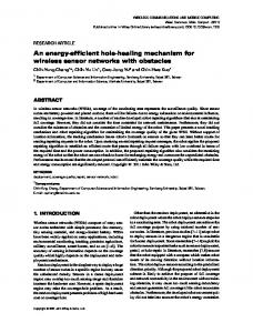
Figure 3. FTP throughput between two wireless nodes as the node with a directional antenna (6dBi) changes its orientation from 0 to 315°
Transmission power reduction in directional mode (Pdiff) \
Figure 2. Radiation patterns of a beam (in grey), its neighbor, and the omni antenna with 0dBi gain
3.1 Directional Antennas We first provide the rationale behind the use of directional antennas in BeamSwitch. Form Factor: BeamSwitch is motivated by the commercial availability of directional antennas in small form factors that can be employed in Smartphones and portable computers. For example, the patch antennas used in our prototype have an area of 1.56 inch2 [1]. In fact, recent advancement in micro-strip antenna technologies promises even smaller patch antennas to fit on the thin edges of Smartphones, e.g. see [2, 3]. Therefore, even small devices like Smartphones could support up to six directional patch antennas on their six surfaces with careful design. Performance Improvement: Our measurements show that directional antennas can provide better performance than omni-directional ones. We employ the wireless open-access research platform (WARP) developed by Rice University. In the experiments, two WARP boards are used and placed 15 meters apart indoor. One board is always equipped with a Telex 2406 omni-directional antenna [12]. We measured the FTP throughput between the two boards when the other board is equipped with the same omni-directional antenna and a directional antenna with 6dBi antenna gain (Telex 2401A) [1], respectively. We also measured the throughput when the transmission power from the directional antenna is lowered by 3dB, or by half. We orient the board with the directional antenna to eight different directions in a full circle and repeat all measurements for each orientation. Figure 2 clearly shows that the directional antenna outperforms the omni antenna even when 3dB lower transmission power is employed for a considerable range of orientation. This is because directional transmission can lead to much smaller delay spread [13] at the receiver because there are fewer paths. Figure 2 also highlights the potential risk of using directional antennas: when the antenna is not oriented properly, there can be significant degradation in throughput. In the worst case, the communication is almost completely terminated. Therefore, the key challenge to BeamSwitch is to select the right beam for any transmission.
Lower Power Consumption: As described above, directional antennas can focus radiation into the right direction and allow a lower transmission power to achieve comparable or better performance. This leads to lower power consumption by the wireless network adapter. For example, our measurement showed that the Cisco Aironet Wireless Cardbus 802.11 adapter [14] consumes 1.3Watt and 1Watt with 16dBm and 13dBm transmission power, respectively.
3.2 Radiation Pattern of BeamSwitch We next introduce some important concepts of the multiantenna system for later analysis. Figure 3 illustrates the radiation pattern of one beam (in grey) and that of one of its neighbors in the BeamSwitch conformation. For clarity, it ignores the side lobes of the directional antenna. The beam has the highest antenna gain along its dominant, or boresight direction (Direction 1 in the figure). Moving away from the boresight direction, the antenna gain drops. If we draw the radiation pattern of the omni-directional antenna in Figure 3, it will be a complete circle of 0dBi gain. The intersections of this circle and the directional radiation pattern define the points from which the directional antenna gain becomes lower than the omni antenna. Direction 3 in the figure shows one of the two intersections. From the boresight direction to these points, the directional antenna will have an equal or higher gain than the omni antenna. Therefore, we call this range of better gain of the directional antenna, denoted by . If we draw a circle of the transmission power reduction in the directional mode ( ) in Figure 3, the intersections of the circle and the beam radiation pattern, as marked by Direction 2, denote the points that the directional antenna can compensate the reduced transmission power with its antenna gain, in comparison to the omni mode. We call this range of better transmission, denoted by . The intersection of the patterns by two adjacent beams, e.g. as marked by Direction 4 in Figure 3, defines the direc-
3
tion with the least antenna gain that can be achieved by all . the directional beams. We denote this least gain as must be higher than 0dBi for the Apparently, BeamSwitch to achieve comparable performance as a conventional omni-directional antenna-based design. Note that 0 is equivalent to that the range of better gain increases from all beams cover all directions, or 360°. as the number of beams increases.
4. Beam Assessment and Selection BeamSwitch consists of two key modules in software. Beam assessment determines whether the current beam is fit or there is a need to change the beam. Once there is a need, beam selection suggests the next beam to use and assess until a fit beam is identified.
4.1 Beam Assessment BeamSwitch leverages the acknowledgement mechanism common to many wireless broadband technologies, including 802.11 and 802.16 (in TDD mode). Because many wireless technologies do not provide the RSSI information at the MAC layer, BeamSwitch obtains it directly from the wireless transceiver and calculates it for each received frames. Modern wireless transceivers usually provide hardware or software interface for instant RSSI, e.g. MAX 2829 used in our prototype [15]. BeamSwitch keeps the RSSI of most recent ACK frames and most recent data frames in a FIFO buffer of 50 entries. Although the data frames are received in the omni mode, they provide information about channel changes that affects both modes, e.g. the mobile device moves away from the access point. To compensate the antenna gain difference between the omni and directional modes, we add a constant number to the RSSI of a data frame before entering it to the buffer. The constant number is calculated as the average antenna gain difference between the directional and omnidirectional antennas over the range of better gain. Whenever an ACK is received, BeamSwitch compares its RSSI to the average of the buffer. It considers the current beam as invalid and there is a need for beam change if the ACK RSSI is lower than the average of the buffer. When this happens, BeamSwitch will choose the next beam to use according to the beam selection module. BeamSwitch employs the RSSI of ACK frames from the access point as much as possible. During busy transmission time, BeamSwitch always employs the same beam to transmit a data frame and receive its ACK. Therefore, it assesses the fitness of the current beam with every data frame. During idle time, if a BeamSwitched node overhears a data frame from its peer destined to the access point, it switches to the most recent beam to overhear the subsequent ACK frame from the access point for beam assessment. Since the BeamSwitched node only uses directional antennas for ACK frames destined to peers, there is no risk of missing incoming data.
4.2 Randomized Beam Selection Once BeamSwitch determines that the current beam is unfit, it employs the beam selection module to identify the next beam to use and assess. The beam selection module operates as a finite state machine. It is reset whenever a fit beam is found. Since BeamSwitch has no more than six directional antennas, it employs the following procedure before a valid antenna is found. • The first and second times the beam selection module is called since the directional information becomes invalid, it tries the two neighbors of the current directional antenna in a random order. The rationale is that device movement is relatively slow in comparison to the time taken for multiple DATA-ACK exchanges. • The third time, it tries the opposite of the original directional antenna; and the fourth and fifth times, it tries the neighbors of the third position in a random order. The rationale is that if an antenna and both its neighbors are wrong, BeamSwitch may have lost track and should try in a very different direction. For a design with at most six beams, BeamSwitch is most likely to have assessed all antennas before the relative direction of the device changes more than a small fraction of the range of better transmission of a beam. For example, for a PHY layer data rate of 12Mbps, the total time for six consecutive transmissions, including possible RTS/CTS exchange, is less than 20ms. Even if the end device changes direction at 360° per second, the total direction change in 20ms will be less than 10°. Motion Estimation for Beam Selection. It is apparent that BeamSwitch is inherently random in which direction to search. As ultra-low power accelerometers have appeared in mobile systems, it is possible to estimate the horizontal movement or rotational direction from the readings of a triaxis accelerometer. The direction information can be incorporated into the beam selection module in its first call: instead of trying the two neighbors in a random order, the neighbor along the right direction is selected. The accelerometer-based procedure apparently assumes that the antenna along the right “direction” is the right antenna.
5. Key Factors in BeamSwitch We next provide an analysis of how various factors affect the performance of BeamSwitch.
5.1 Benefit and Cost from BeamSwitch Apparently, the benefit of BeamSwitch is due to enhanced energy efficiency and communication quality when the best beam is used. The cost is due to assessing beams to identify a right one. Because BeamSwitch employs outgoing data frames and their ACK frames to assess a beam, the cost is related to the risk of retransmission when transmitting data frames from unfit beams.
5.2 Design Space of Antenna Configuration As described earlier, there are three properties of the multiantenna system used in BeamSwitch, namely, beam radia-
4
tion pattern, transmission power reduction in the directional mode ( ), and the number of beams. Each of these three properties may have a double-edged impact, detailed below. Moreover, they are not only interrelated but also their impact is highly dependent on node mobility. It is our objective to identify a suite of antenna configurations that have robust and consistent performance under various external conditions. Number of Beams: The more the number of beams, the finer is the choice of beams in BeamSwitch, and thus, a higher gain is possible with the best beam and the higher . Therefore, a higher number of beams leads to better throughput and energy efficiency when the best beam is identified. On the other hand, with more beams, the cost of identifying the best beam increases since it takes more time to identify the best beam. Therefore, the impact of the beam number is highly dependent on mobility. When mobility is low, the gain from the best beam will dominate and the more beams the better. In contrast, when mobility is high, the cost from selecting the best beam increases as the number of beams increase. We note that given the directional antenna, the number of beams in BeamSwitch can actually come from a small range. On one hand, BeamSwitch has to ensure 0 or that the range of better gain of all beams covers all direction. Therefore, there is a lower bound on how many beams it needs. For example, the 6dBi antenna used in our prototype requires at least three beams to roughly cover all direction. On the other hand, adding beams will eventually make BeamSwitch worse under mobility as analyzed above by complicating the search for fit beams. In addition, the number of beams is further limited by the form factor of mobile devices, which normally have four surfaces around 360° and at most six surfaces. Antenna Pattern: We focus the discussion on the most relevant property of a directional antenna, i.e. the maximum antenna gain, and neglect other secondary properties, such as the exact shape of the radiation pattern and the side lobes. Firstly, the higher the antenna gain, the more focused the antenna. As a result, we expect a better performance and efficiency when the best beam is indeed selected. On the other hand, a more focused antenna, leads to a smaller , and potentially a smaller too. The best beam can quickly become unfit under mobility. Therefore, we expect more frequent need for beam assessment under mobility and therefore more retransmissions when the beams are more focused. It is important to note that the antenna gain and the number of beams are related. The higher gain, the more beams are needed to cover 360° with of all beams. This reinforces the positive and negative impacts of more focused beams without and with mobility, respectively. ): TransmisTransmission Power Reduction ( , mostly sion power reduction in the directional mode, impact the performance and efficiency when a best beam is
selected. More reduction leads to more energy saving but may risk loss in performance. As a result, we expect to see that performance decreases and energy efficiency improves first and then drops when transmission power decreases and therefore retransmissions increase. The key of BeamSwitch is to maintain a better or comparable performance as omniantenna systems with higher energy efficiency. fore, is interrelated to the antenna gain and the number of beams because the higher , the smaller . With a higher , more beams or higher antenna gains are required to cover 360° with of all beams. In our evaluation, we denote an antenna configuration by a triplet (maximum antenna gain, transmission power reduction in directional mode, number of beams). For example, the default configuration in our evaluation is (6,3,3).
5.3 Factors External to BeamSwitch Design We identify multiple external factors that have a significant impact on the performance of BeamSwitch. Mobility: Mobility, in particular rotational mobility, necessitates more frequent need of beam assessment and therefore increases the cost of BeamSwitch. Much of our evaluation will be focused on the impact of mobility. Communication traffic: The pattern of communication traffic impacts BeamSwitch in three ways. The first is coupled with mobility. BeamSwitch assesses beams with outgoing data frames and it first searches the two immediate neighbors of the last used beam. Therefore, the cost of assessment will be smaller when the traffic is continuous than when it is sporadic because the adjacent beams may become unfit during the idle interval under mobility. Second, a high transmission data rate will have low assessment cost. This is because BeamSwitch assesses the current beam with each outgoing data frame. A higher transmission data rate makes it more likely that BeamSwitch will identify the right beam in its first two tries. Lastly, because BeamSwitch only improves transmission, it is more effective improving wireless communication with more transmission. Therefore, we expect it to be more effective with FTP upload than with VoIP. Channels: The channel, including multi-path effect, noise, interference, and peer contentions, impact both the cost and benefit of BeamSwitch as relative to conventional antenna-based systems. The cost of BeamSwitch under channels with little multi-path effect is high because an unfit beam will lead to very poor communication. Moreover, the hidden node problem will be the worst under these channels because peers not along the propagation pathway are unlikely to hear the transmission from a BeamSwitched device. On the other hand, the benefit of BeamSwitch is also high under these channels because the antenna gain can be fully realized. Similarly, while the presence of peers may introduce the hidden node problem, peers’ communication with the access point can create risk-free opportunities for a BeamSwitched node to assess and select beams even during its idle time.
5
6. Experimental Evaluation
1 Isotropic antenna
We have implemented BeamSwitch on the WARP platform from Rice University [16] and conducted a series of controlled experiments to evaluate its real-world performance. Our main motivation for using WARP was its support of DATA-ACK based communication at time-scales which are representative of commercial deployments, and thus allows us to correctly assess the interaction between mobility timescales and data communication time-scales.
3 directional antennas
WARP
Laptop Controllable motor
6.1 WARP-Based Prototype 6.1.1 Hardware Implementation The WARP platform has hardware interfaces for up to four RF chains and the RF daughterboard has two antenna ports that can be selected in software. Therefore, instead of using an antenna switch to select from multiple antennas, we have to employ multiple RF daughter-boards for more than two antennas. However, at any given time, only one RF daughterboard is active and the idle one is powered off. The switch time is about 50ns according to the datasheet [15]. Moreover, the current open-source WARP PHY and MAC implementation only supports the use of two RF daughterboards simultaneously. Therefore, we are limited to three directional and one omni-directional antennas in our experimental evaluation. However, we will use simulations for more antenna configurations in the next section. For the omni mode, we employ Telex 2406 omnidirectional antenna [12], which is the closest to being omnidirectional we can find in retail market. For the directional antennas, we employ directional antennas with maximum gain of 6dBi [1] and 9dBi [17], respectively. We lower the transmission power by 2 to 4dB for the directional mode. Unless otherwise specified, the default antenna configuration is (6,3,3). It is important to note that when the 9dBi directional antennas are used, the range of better gain of all three of them can only cover about 320° out of a full circle; and the corresponding is -2dBi (See Section 3 for definitions). Therefore, antenna configurations of (9,*,3) in our experiments are not practically suitable. However, we include them to illustrate the impact of different antenna gains. 6.1.2 System Implementation and Benchmarks The WARP platform comes with 802.11-like PHY and MAC layers. We implement BeamSwitch based on modifying existing code base. The implementation uses 2.4 GHz and employs QPSK with 12Mbps PHY layer data rate. Our experiments involve two or three WARP boards: one with BeamSwitched implemented, acting as the wireless interface for a laptop computer; the second without BeamSwitch, acting as the wireless interface for another laptop serving as the access point. The optional third board acts as a peer node to the BeamSwitched node. The boards are placed at the same height and 15 meters from each other. We choose 15 meters because communication indoor is no longer reliable even with the omni-directional antenna at a longer dis-
Figure 4. WARP-based BeamSwitch prototype on the rotatable platform for experimentation
tance, likely due to the challenging propagation environment indoor. We test our prototype with four benchmark applications: audio (Music) and high-definition video (Video) streaming using VLC media player, FTP a large file (FTP), all from the BeamSwitched end, and Remote Desktop (R. Desk) with the BeamSwitched end as the remote end. Our benchmarks are limited because the WARP platform cannot communicate with an 802.11 device directly. Each measurement lasts five minutes for all benchmarks and involves 6000 to 45000 data frames, depending on the benchmark.
6.2 Mobility and Propagation Environment To stress BeamSwitch with controllable mobility, we build a motor-driven rotating platform to hold the batterypowered BeamSwitched end. The motor can rotate from 90°/s to 360°/s. Figure 4 shows the BeamSwitch prototype on the rotatable platform. It is also important to note that random change in the rotating direction will not make a difference because the beam selection module is inherently random in its search direction. It is important to note that mobile devices, including cell phones, can rarely rotate 360°/s. A video demo is available at [18] We have evaluated the prototype with three propagation environments. The first, Outdoor, is an open space on a university campus. It is close to a Ricean channel where multipath effect is highly limited. The second, Indoor, is inside an office building on the same campus. It is close to a Rayleigh channel where multi-path effect is abundant. The third environment, Indoor with People, is similar to the second except that we have two human subjects move around the BeamSwitched end randomly at a typical walking pace to introduce changes in the propagation. There are multiple 802.11 networks inside the building and they are actively used.
6.3 Evaluation Metrics We evaluate BeamSwitch on its energy saving and impact on communication quality.
6
20 15 10 5
Music FTP
0 0
Video R. Desk
90
180
25
EPB reduction (%)
EPB reduction (%)
EPB reduction (%)
25
20 15 10 5
Music FTP
0
360
0
BeamSwitch Rotating Speed (°/s)
Video R. Desk
90
180
25 20 15 10 5 0
360
Video R. Desk
90
180
360
BeamSwitch Rotating Speed (°/s)
BeamSwitch Rotating Speed (°/s)
(a) Outdoor
Music FTP
0
(b) Indoor
(c) Indoor 2
Music FTP
0
90
180
Video R. Desk
35 30 25 20 15 10 5 0
Music FTP
360 Omni
0
BeamSwitch Rotating Speed (°/s)
90
Video R. Desk
180
RR (%)
35 30 25 20 15 10 5 0
RR (%)
RR (%)
Figure 5. Energy per bit (EPB) reduction for three propagation environments 35 30 25 20 15 10 5 0
(a) Outdoor
0
360 Omni
BeamSwitch Rotating Speed (°/s)
Music FTP
90
Video R. Desk
180
360 Omni
BeamSwitch Rotating Speed (°/s)
(b) Indoor
(c) Indoor 2
Figure 6. Retransmission rate (RR) for three propagation environments. Note those for the conventional omni-antenna design are shown for comparison 1
1
Music
1
Video
BeamSwitch Omni 0.5
0.5
0
0
0
5
10
0
5
Remote Desktop
BeamSwitch Omni
BeamSwitch Omni
0.5
0
1
FTP
0.5
0 0
10
BeamSwitch Omni
5
Delay (ms)
10
0
5
10
Delay (ms)
Delay (ms) Delay (ms) Figure 7. Cumulative data delay distributions under Indoor with People as BeamSwitched node rotates at 360°/s
6.3.1 Energy Efficiency We evaluate energy efficiency with energy per bit, calculated as the total energy consumed by the WNIC on the BeamSwitched end divided by the number of data bits transmitted from it (Figure 5). We use total energy instead of transmission energy because BeamSwitch can increase receiving energy consumption by engendering retransmissions. As a result, “energy per bit” can be significantly larger than “transmission energy per bit”. We report reduction in the energy per bit of the BeamSwitched end as compared to that of a conventional, omni-directional end under otherwise exact experimental settings. Because BeamSwitch only reduces transmission power, “energy per bit reduction” as reported later can be significantly lower than “transmission energy per bit reduction.” As a result, we will also see that
“energy per bit reduction” becomes smaller for traffic with less transmission. Because WARP was not intended for mobile platforms, its RF system was not optimized for power and the transmission power has a negligible impact on its power consumption. In contrast, commercial 802.11 WNICs demonstrates a much higher impact as shown in Section 3. Therefore, we employ a power model constructed with our measurements of a Cisco Aironet Wireless Cardbus 802.11 network interface card (NIC) [14] and calculate the total energy consumption of the whole card using traces collected from the BeamSwitched WARP. 6.3.2 Communication Quality We evaluate the impact of BeamSwitch on communication quality with throughput, data retransmission rate, and frame delay distribution. We calculate throughput by dividing the
7
40
RR (%)
BeamSwitch
BeamSwitch‐ME
Omni
30 20 10 0 FTP‐Outdoor
R. Desk‐ Outdoor
FTP‐Indoor2
R. Desk‐ Indoor2
Figure 8. Motion estimation (BeamSwitch-ME) reduces retransmission rates (RR) of BeamSwitch at 360°/s to very close to the conventional omni design
number of correctly transceived data bits by the total time length of simulation. Note that transceiving can be intermittent and therefore throughput can be much smaller than the data rate used in transceiving. We calculate retransmission rate as the percentage of retransmitted data frames out of all transmitted data frames from the BeamSwitched end (Figure 6). We calculate data delay as the delay between the time of transmission at the BeamSwitched end and the time of correct reception (Figure 7).
6.4 Measurement Results Our measurements clearly show that significant gains are possible with BeamSwitch. It can improve both energy efficiency and communication quality even when rotating at 90°/s. We observe lower retransmission rates, lower data loss rates, up to 20% throughput improvement for FTP, and up to 20% energy per bit reduction for Video, when the BeamSwitched node is rotating up to 90°/s in all three propagation environments. BeamSwitch only slightly degrades the communication quality even when continuously rotating at 360°/s. Yet there is no frame delay beyond 10ms, as shown in Figure 7. For Music, Video, and Remote Desktop, there is no humanperceptible difference in the media quality or response time. For FTP, throughput degrades by at most about 10% when continuously rotating at 360°/s. It is important to note that mobile devices are very unlikely to continuously rotating at 360°/s under realistic settings. Our own personal experience is that the rotating is more likely to be sporadic; and continuous direction changes are only introduced by linear mobility and are therefore slow. Henceforth, we expect the gain of BeamSwitch in performance and energy efficiency will dominate under realistic mobility. Moreover, as our experiments show, the communication quality impact due to sporadic rapid rotational mobility is also very small and not perceptible to the end user.
6.4.1 Impact of External Factors Our experiments confirmed our analysis in Section 5 regarding the impact of external factors. Communication Traffic: BeamSwitch has a relatively higher impact on the communication quality for Music and Remote Desktop (R. Desk) than Video and FTP. This is consistent with our analysis. Music generates a relatively low throughput about 128 Kbps, only about 20 frames per second, and Remote Desktop generates a busty traffic. As discussed in Section 5, BeamSwitch does better with a higher throughput and continuous communication. BeamSwitch achieves higher energy per bit reduction for Video than for FTP because Video is almost 100% data transmission and FTP requires a small percentage of data reception for FTP acknowledgements. Channels: we see that BeamSwitch affects both energy efficiency and communication quality (positively or negatively) in a similar way under all three channels. This can be ascribed to the double-edged contributions by multipath effect and interference described in Section 5. Moreover, although BeamSwitch degrades FTP throughput relatively more Indoor at 360°/s, it actually improves it relatively more Indoor at 90°/s (see Figure 10). This highlights how mobility can change the balance of the double-edged contributions by multipath effect and interference. 6.4.2 Antenna Configurations Because of our prototype is limited by at most three directional beams, we only evaluate the impact of transmission power reduction here. We will have resort to simulation to extensively evaluate the impact of the number of beams in Section 7.
Figure 9 presents the tradeoffs between throughput and energy per bit reduction made by FTP Indoor with three different rotating speeds and various antenna configurations, i.e. (6,*,3) and (9,*,3). In the stationary case, we stage the BeamSwitched node with a beam pointed toward the access point. Therefore, the station performance of BeamSwitch should be considered as its best possible performance. ): Our results Transmission Power Reduction ( show that transmission power reduction is most related to the tradeoff between energy efficiency and communication leads to more retransquality for all cases. Increasing missions and higher energy efficiency at first. Eventually, the cost associated with retransmissions can overtake the energy saving from lower transmission and increasing leads to lower efficiency. Such an impact is identical with transmission power reduction and can be leveraged together with transmission power control, which is an orthogonal power-saving mechanism and has been extensively studied, e.g. see [19]. In particular, although fixed transmission power was used in both the directional and omni mode in our evaluation, transmission power in the directional mode can be dynamically determined to provide the desirable tradeoff between efficiency and communication quality. Antenna Gain: While (9,*,3) configurations cannot cover 360° with the range of better gain of all beams and
8
4 3 2 (6,2,3) (9,2,3)
1 0
(6,3,3) (9,3,3)
(6,4,3) (9,4,3)
11 12 13 14 15 16 17 18 19
5 Throughput (Mbps)
Throughput (Mbps)
Throughput (Mbps)
5
4 3 2 1
(6,2,3) (9,2,3)
(6,3,3) (9,3,3)
(6,4,3) (9,4,3)
0
(6,3,3) (9,3,3)
(6,4,3) (9,4,3)
3 2 1 0 Energy Per Bit Reduction (%)
Energy Per Bit Reduction (%)
(a) Stationary
(6,2,3) (9,2,3)
4
9 10 11 12 13 14 15 16 17
11 12 13 14 15 16 17 18 19
Energy Per Bit Reduction (%)
5
(b) 90°/second
(c) 360°/second
BeamSwitch(0°/s) BeamSwitch(90°/s) BeamSwitch(360°/s) Omni
4
100
100
FTP
Remote Desktop
%
6
%
Throughput (Mbps)
Figure 9. Tradeoff made by BeamSwitch with various antenna configurations FTP (Indoor). The dashed line represents the throughput achieved with a conventional antenna system.
1
2
1
3
50
50
0
0
2
3
2 0
90 Outdoor
Indoor
Indoor with People
Figure 10. FTP throughput
2 , they achieves better tradeoffs than has their counterparts with 6dBi max antenna gain in the Pareto sense, i.e. their tradeoff points appear to the upper-right of those of their counterparts, when mobility is low (stationary and 90°/s). Unfortunately, they suffer substantial performance degradation with high mobility (360°/s) in comparison to the omni design. In contrast, (6,*,3) maintains very close performance to that of the omni design. Having a 360° range of better gain and 0 is apparently important to robust and consistent performance under extreme mobility. Because the impact of the antenna gain is highly related to the number of beams, we will further discuss this later in Section 7. 6.4.3 Effectiveness of Beam Selection Figure 11 shows that BeamSwitch identifies the fit beam in the first two tries in over 80% times even when the BeamSwitched end rotates at 360° per second and under Indoor with People. We also emulate the assistance of motion estimation using the similar method in Section 4.2 and measure FTP and Remote Desktop under Indoor 2 and Outdoor at 360°/s. Figure 8 presents the retransmission rates for them along with those for the omni-directional design. Our measurement shows the reduced rates are very close to or even lower than those for the conventional antenna counterpart. This
360
90
360
Rotating speed (°/s) Rotating speed (°/s) Figure 11. The numbers of trials before the beam selection module finds the right direction under Indoor 2
highlights the potential of motion estimation in helping BeamSwitch better guaranteeing communication quality.
7. Simulation-Based Evaluation We complement our prototype-based evaluation with simulations based on Qualnet. The simulations enable us to address the limitations of our prototypes in three aspects, namely, antenna system configurations with more beams, more complicated mobility, and the presence of peers.
7.1 BeamSwitch in Qualnet We have modified the PHY and MAC layers of the Qualnet simulation tool to simulate BeamSwitch. We have implemented the radiation models for two commercially available directional antennas with maximum antenna gains of 6dBi [1] and 9dBi [17], respectively. Qualnet provides an energy model for the WNIC derived from the WaveLAN specification [20]. Unless otherwise specified, all simulations are conducted with the BeamSwitched device placed at 75 meters from the access point. All simulations are based on the 11Mbps PHY layer. The default RF configuration is identical with that in our prototype: the directional antenna of 6dBi max gain, 3dB lower power transmission, and 3 directional antennas or (6,3,3). Qualnet allows us to move and rotate each node for both linear and rotational mobility. We employ the built-in Ricean channel from Qualnet. This is an extremely challenging channel to BeamSwitch
9
4 (6,3,3) (6,3,4) (6,3,6)
B
(6,4,6)
2
(9,4,6)
RR (%)
RR (%)
3
A
1
0 9
10
11
12
13
14
15
16
17
11 10 9 8 7 6 5 4 3 2 1 0
(6,3,3) (6,3,4)
(6,4,6)
A
(9,4,6)
9
18
(6,3,6)
B
10
11
12
13
14
15
16
17
18
Energy Per Bit Reduction (%)
Energy Per Bit Reduction (%)
(a) Rotating at 90°/s
(b) Rotating at 360°/s
Figure 12: Tradeoffs between retransmission rate (RR) and energy per bit reduction by various RF configurations for VoIP. Dashed line shows the retransmission rate of a conventional omni antenna-based system
because it magnifies the hidden node problem and the cost of beam assessment, as discussed in Section 5. Unfortunately, Qualnet does not provide proper Rayleigh channel models for directional antennas. Note we disable RTS/CTS in all simulations.
7.2 Antenna Configurations Our prototype is limited to at most three beams. Therefore, we were able to explore the impact of transmission power reduction only. Using simulation, we examine the coupled impact of the number of beams and antenna gains. We simulate the performance of various antenna configurations under different combination of rotating speeds with VoIP. We evaluate each with its tradeoff between energy per bit and retransmission rate. Number of Beams: Our simulation confirms our analysis in Section 5.2. Circle A in
Figure 12 shows that the retransmission rate significantly increases and the energy efficiency remains about the same as the number of beams increases from 3 to 4 and to 6 for (6,3,*) configurations. We observe the range of better transmission (or , as defined in Section 3) of (6, 3,*) configurations is 95° and therefore (6,3,3) will cover 285° for better transmission gain and (6,3,4) will cover all 360° in an overlapping manner. We conjecture the upper bound of the number of beams should be the least number that has the range of better transmission cover all 360°. Antenna Gain: In Section 5, we showed that the number of beams in BeamSwitch can only come from a small range. Similarly, we show that the directional antenna gain, or how focused the beams are in BeamSwitch, also comes from a small range. On one hand, the antenna gain is the reason BeamSwitch improves efficiency and performance; therefore, the higher, the better. For example, Circle B in
Figure 12 shows that (9,4,6) improves (6,4,6). On the other hand, a higher antenna gain requires more beams to cover all direction with the range of better gain or the range of better transmission. And the maximum number of beams is limited by the form factors to at most six. To conclude, we observe (6,*,3) and (9,*,6) provide Pareto optimal tradeoffs. In particular, (6,*,3) indeed provides a robust and consistent performance at least close to Pareto
optimality for BeamSwitch, as demonstrated by both measurements in Section 6 and simulations.
7.3 Complicated Mobility In Section 6, we mentioned that the randomness in the beam selection procedure makes evaluation with random direction changes unnecessary. We have simulated BeamSwicth with rotational mobility and random direction changes. Our results confirm that random direction changes do not introduce any noticeable difference in either energy efficiency or communication quality. As we recall from Section 4, BeamSwitch updates the threshold for detecting the need of beam change even in the omni mode, in order to distinguish between RSSI changes introduced by direction change and those by the mobile end moving away from its partner. To show how effective it is, we simulate that a BeamSwitched end linearly moves away from the access point at 2 meters per second from 20 to 80 meters with VoIP traffic between them. Our results show that the retransmissions rate is below 1% and over 5% before and after the threshold updating in the omni mode is disabled, respectively. This illustrates the usefulness of updating even in the omni mode.
7.4 Hidden Node Problem As discussed early, BeamSwitch may exasperate the hidden node problem because it reduces the chance that peers hear each other. We simulate the following five scenarios to see how serious this problem may be with two network configurations shown in Figure 13 and Figure 14. We choose these two configurations because they amplify the hidden node problem. In Scenario I, four conventional omni-directional mobile nodes are symmetrically distributed along a circle of 200-meter radius centered on an AP, as illustrated in Figure 13. Since transmission range with 15 dBm transmission power is 200 meters, this configuration guarantee that any mobile node interferes with each other. In this scenario all nodes seek to send a large file to the AP with FTP as fast as possible simultaneously. Scenario II differs from Scenario I only in that the four mobile nodes are BeamSwitched with the default RF configuration (6,3,3). In Scenario III, four directional mobile nodes are located along a circle of 100-
10
FTP FTP
FTP
100 or 200 meters
75 meters 150 meters
Figure 13. Symmetric network configuration for exposing the hidden node problem
meter radius centered on an AP. In this situation we are aware that mobile nodes can interfere with other mobile nodes since relative distance between the mobile nodes is shorter. In Scenarios IV and V, we evaluate BeamSwitch with an asymmetric network configuration as illustrated in Figure 14. In Scenario IV, we place two omni-directional nodes at 75 and 150 meters away from the AP, respectively. In Scenario V, we place two BeamSwitched nodes rather than omni-directional nodes in the same way as in Scenario IV. Findings: Our simulations show that in Scenarios II and III, there is 7.9% and 2.5% degradation in average node throughput, respectively, in comparison with that in Scenario I. In the extreme case of Scenario V, we observe 10.8% and 10.1% average throughput degradation for the BeamSwitched nodes placed at 150 and 75 meters away from the access point, respectively. This indicates that the communication quality degradation due to the hidden node problem introduced by BeamSwitch is marginal. This is not surprising indeed. Recall that BeamSwitch only stays in a directional mode during the frame exchange for a data frame transmission; it stays in the omni mode otherwise. Therefore, BeamSwitched nodes can still overhear transmission from the AP to their peers and thus largely avoid acerbating the hidden node problem. Note that we disable RTS/CTS in the simulation. Because BeamSwitch transceives RTS/CTS frames with the omni-directional antenna, the use of RTS/CTS will allow BeamSwitch to further address the hidden node problem.
8. Discussions and Future Work We next discuss limitations in the reported work and highlight research opportunities brought by BeamSwitch. Rotational Mobility: The mobility employed in our evaluation, both rotational and linear, is limited to that within the same plane as the BeamSwitched node and its access point are and the same plane as the boresight of the directional beams. While we acknowledge this is not equal to mobility with all degrees of freedom, such planar mobility substantially stresses directional antennas because they are
Figure 14. Asymmetric network configuration for exposing the hidden node problem
supposed to focus radiation power into a narrow angle in the same plane. Therefore, we consider it as adequate in evaluating BeamSwitch. Nonlinearity of Power Amplifier: By reducing transmission power, BeamSwitch reduces WNIC power mainly through the power-hungry power amplifier. However, the reduction in power consumption may not always be proportional to the transmission power reduction because the efficiency of a power amplifier is not constant but dependent on its out power. Therefore, BeamSwitch will benefit more in energy efficiency from power amplifiers that can provide high efficiency for lower transmission power, such as [21] and emerging tunable power amplifiers [22]. Mechanism vs. Policy: We would like to emphasize BeamSwitch as a power-saving mechanism, as orthogonal to existing ones, e.g. power control and power management. Simulation and experiments reported in this work clearly show its strength and limitation under different mobility, radio propagation environment, and traffic pattern. Therefore, there is a need for “policy” research in adaptively applying BeamSwitch based on the propagation environment and traffic patterns in order to maximize its energy-saving potential, particularly along with other power-saving mechanisms. BeamSwitch for Ad Hoc Networks: In this work, we intended BeamSwitch as a solution for mobile devices operating in the infrastructure mode, or communicating with a single access point. However, it is possible to extend BeamSwitch to devices operating in the ad hoc mode. A straightforward solution is to run a separate incarnation of BeamSwitch software, including its internal states, to cope with each node with which the BeamSwitched node is communicating with. The same BeamSwitch multi-antenna system can be shared by all such incarnations. The geographical location correlation between the peers can also be employed to improve beam assessment and selection. Theory of Directional Communication: Our work also strongly motivates the need for a deeper theoretical understanding of directional communication under rotational mobility. As evident from the lack of support for directional
11
antennas under Rayleigh channels in Qualnet, we currently do not have adequate models for directional channels under various propagation environments. Such channel models would lend tools to provide analytical models for the performance of BeamSwitch.
[4]
9. Conclusions
[5]
We presented BeamSwitch, a system solution to save power in wireless communication for mobile systems. BeamSwitch employs a special multi-antenna system with a single RF chain, multiple directional antennas, and a regular antenna; it utilizes RSSI information from the transceiver, and reacts to MAC events to select the best antenna for data transmission and its acknowledgement reception. It stays with the regular antenna for all other activities. We presented an 802.11-compliant implementation which requires no cooperation from the infrastructure or peers. BeamSwitch is orthogonal to existing wireless power-saving mechanisms by reducing directional energy waste in radiation. We reported an extensive evaluation of BeamSwitch based on both prototype measurements and simulation. Our evaluation clearly demonstrates the effectiveness of BeamSwitch in improving energy efficiency (up to 20%) of the WNIC with better or close communication quality compared to conventional antenna-based systems. BeamSwitch achieves this under extreme mobility (changing direction at 360°/s) and under various radio propagation environments. In addition, our work revealed the potential improvement to BeamSwitch from sensor-based motion estimation. Our evaluation also showed that a simple antenna configuration with only three beams and therefore low form factor requirement can achieve robust and consistent improvement over conventional omni antenna based systems. Such a design may be readily implemented on mobile systems like laptop computers and Smartphones.
Acknowledgements The work was supported in part by NSF awards CNS/CSREHS 0720825, CNS/NeTS-WN 0721894, CNS/CRI 0751173, CNS-0551692, CNS-0551692, and support from the TI Leadership University program.
[6]
[7]
[8] [9]
[10]
[11]
[12]
[13]
References [1]
[2]
[3]
Telex, 5dBi Patch Antenna. http://www.telex.com/Wireless/product.aspx?Mark etID=1&CategoryID=3&ProductID=49, 2008. L. Desclos, Y. Mahe, S. Reed, G. Poilasne, and S. Toutain, "Patch antenna size reduction by combining inductive loading and short-points technique," Microwave and Optical Technology Letters, vol. 30, pp. 385-386, 2001. F. Jolani, A. M. Dadgarpour, and H. R. Hassani, "Compact M-slot folded patch antenna for WLAN," Progress In Electromagnetics Research Letters, vol. 3, pp. 35–42, 2008.
[14] [15]
[16] [17]
[18]
12
V. Navda, A. P. Subramanian, K. Dhanasekaran, A. Timm-Giel, and S. Das, "MobiSteer: using steerable beam directional antenna for vehicular network access," in Proc. Int. Conf. Mobile Systems, Applications and Services (MobiSys). vol. 11, 2007, pp. 192-205. A. P. Subramanian, V. Navda, P. Deshpande, and S. R. Das, "A measurement study of inter-vehicular communication using steerable beam directional antenna," in Proc. ACM Int. Wrkshp Vehicular Inter-Networking (VANET) San Francisco, CA, 2008. R. Ramanathan, J. Redi, C. Santivanez, D. Wiggins, and S. Polit, "Ad hoc networking with directional antennas: a complete system solution," IEEE Journal on Selected Areas in Communications, vol. 23, pp. 496-506, 2005. J. C. Liberti and T. S. Rappaport, Smart Antennas for Wireless Communications: IS-95 and Third Generation CDMA Applications: Prentice Hall PTR Upper Saddle River, NJ, USA, 1999. T. Sarkar, Smart antennas: Wiley-Interscience Hoboken, NJ, 2003. S. Cui, A. J. Goldsmith, and A. Bahai, "Energyefficiency of MIMO and cooperative MIMO techniques in sensor networks," IEEE Journal on Selected Areas in Communications, vol. 22, pp. 10891098, 2004. H. Dumanli and L. Zhong, Beam forming power analysis: http://www.recg.org/publications/dumanli08beamf orming.pdf, 2008. R. R. Choudhury, X. Yang, R. Ramanathan, and N. H. Vaidya, "Using directional antennas for medium access control in ad hoc networks," in Proc. ACM Int. Conf. Mobile Computing and Networking (MobiCOM) Atlanta, GA, 2002. Telex, Omni-directional 2406 antenna. http://www.telex.com/Wireless/Product.aspx?Mark etID=1&CategoryID=3&ProductID=21, 2008. J. C. I. Chuang, "The effects of time delay spread on portable radio communications channels with digital modulation," IEEE Journal on Selected Areas in Communications, vol. 5, p. 879, 1987. Cisco, Cisco Aironet 802.11a/b/g Wireless CardBus Adapter, 2008. Maxim Integrated Products, Datasheet for MAX2828-MAX2829, Single-/Dual-Band 802.11a/b/g World-Band Transceiver ICs, 2008. WARP, http://warp.rice.edu/, 2008. L-COM Global Connectivity, RE08P: HyperGain 2.4 GHz 8 dBi Round Patch Antenna: http://www.lcom.com/multimedia/datasheets/DS_RE08PRTP.PDF. BeamSwitch Demo Video, http://www.recg.org/publications/beamswitch.avi.
[19]
[20] [21] [22]
D. Qiao, S. Choi, A. Jain, and K. G. Shin, "Adaptive transmit power control in IEEE 802.11a wireless LANs," in Proc. IEEE Vehicular Technology Conf. (VTC), 2003, pp. 433-437. Scalable Network Technologies, QualNet 4.0 User Guide, 2007. MAXIM, Datasheet for MAX2242: 2.4GHz to 2.5Ghz linear power amplifier. G. Liu, P. Haldi, L. Tsu-Jae King, and A. M. Niknejad, "Fully Integrated CMOS Power Amplifier With Efficiency Enhancement at Power Back-Off," IEEE Journal of Solid-State Circuits, vol. 43, pp. 600-609, 2008.
13