Bent-waveguide modeling of large-mode-area, double-clad fibers for high-power lasers. G. Ronald Hadleyâ , Roger L. Farrowâ¡, and Arlee V. Smithâ . â P. O. Box ...
Bent-waveguide modeling of large-mode-area, double-clad fibers for high-power lasers †
G. Ronald Hadley†, Roger L. Farrow‡, and Arlee V. Smith † P. O. Box 5800, Sandia National Laboratories, Albuquerque, NM 87185 ‡ P. O. Box 969, Sandia National Laboratories, Livermore, CA 94550 Abstract
The design and optimization of high-power fiber lasers and amplifiers requires a detailed understanding of several important physical processes, both linear and nonlinear. The influence of bending on the overlap of the propagating mode as well as its resistance to deleterious nonlinear effects such as self-focusing must be accurately predicted. To this end we have developed a number of models, both analytic and numerical, that allow us to treat these effects in detail. I. Introduction The development of high-power fiber lasers requires a detailed understanding of limitations imposed by high optical irradiances present in the active core. In a well-designed high-power system, the onset of optical damage or nonlinear optical processes ultimately limits the attainable power. As a result, current designs employ large mode area active fibers, with the aim of achieving a dominant lowest-order spatial mode with the largest possible area. Since these fibers will generally support multiple modes, a common practice is to coil the fiber using a diameter small enough to induce mode-dependent bend losses.1 The desired LP01 mode experiences lower bend losses than the higher-order modes, and, below a certain bend radius in the presence of gain, can completely dominate over the other modes. Optimizing the design of a fiber for use in bend-loss mode-filtered lasers or amplifiers requires consideration of the mode losses, mode-field spatial distributions and propagation constants of bent fibers and of beam propagation in fibers with varying bend radii or having orthogonal bend planes. To properly study these effects, we have developed analytical and numerical models for simulating beam propagation in coiled fibers in the presence of gain and loss. The models range in complexity from a semi-analytical eigenmode solver for bent step-index waveguides to fully vectorial finite-difference eigenmode solvers and beam propagation models. The latter models can handle arbitrary refractive-index and rare-earth-ion doping distributions as well as arbitrarily-varying bend radii. Both types of tools were found necessary for treating problems encountered in fiber amplifier simulation. In this paper, we concentrate on the more comprehensive finite difference (eigenmode and beam propagation) models and describe some significant results obtained from their use. To this end, Section II includes a brief discussion of the modeling approach and Section III describes results that are expected to impact the design of future fiber laser systems. II. Discussion of Modeling Approach
Fiber Lasers III: Technology, Systems, and Applications, edited by Andrew J. W. Brown, Johan Nilsson, Donald J. Harter, Andreas Tünnermann, Proc. of SPIE Vol. 6102, 61021S, (2006) · 0277-786X/06/$15 · doi: 10.1117/12.656699 Proc. of SPIE Vol. 6102 61021S-1
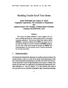
In order to adequately model a general class of fiber laser systems, numerical models were required that were capable of treating an arbitrary fiber shape, arbitrary index and gain profiles, and the effects of bending on both mode shape and radiation loss. To meet these requirements, an eigenmode solver was developed for simulations in which all parameters are invariant in the propagation direction ( z ), and a beam propagation code for the more realistic simulations involving z-dependent parameters. In both cases, a finite difference approach was adopted similar to that previously used to model waveguides of arbitrary shape2. This approach involves the description of regions of piecewise constant index of refraction for the fiber cross section using an irregular triangular grid in which all dielectric interfaces coincide with a triangle boundary. The triangular grid is produced by a grid generator that “stretches” an initially regular grid as required to properly describe the fiber structure. Finite difference equations are derived by integration of the relevant Helmholtz Equation for each field component over a polygonal region surrounding each grid point. These equations are solved by direct matrix inversion using either horizontal or vertical ordering for maximum efficiency. For the present application, the above approach required modification in order to treat effects due to fiber bending. Although these effects are commonly incorporated by simply adding an extra component to the index of refraction that increases linearly with radius, a more rigorous approach was employed by deriving the equations describing the propagation of light in a cylindrical coordinate system as shown in Fig.1. Here, propagation is assumed to take place along the θ direction, with the fiber geometry described in cross section as a function of r and z . The problem was then formulated in terms of the fields H r and H z , with all fields assumed to
z
θ
r Fig. 1 Geometry used for finite difference equation derivation
Proc. of SPIE Vol. 6102 61021S-2
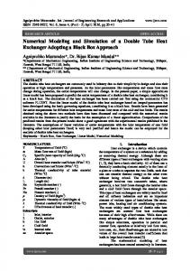
be proportional to the factor eikRθ , where k is the unknown (complex) eigenvalue, or in the case of beam propagation, the reference wavevector. A careful accounting of the interface conditions for both field components at all triangle boundaries separating regions of different dielectric constant then yields a fully vectorial formulation. A semivectorial formulation is easily obtained from these equations by neglecting one field component, and has been found to be very useful since the index contrasts typically found in fibers are small, making the semivectorial approximation well justified. Furthermore, the semivectorial code runs much faster and requires a factor of ~8 less memory. During the above derivation, the radial coordinate is shifted so that the origin is centered on the fiber, and expansions in the small quantity r / R naturally occur, where R is the bend radius. The first term in this expansion for the effective refractive index can be shown to be identical to the commonly-employed linear index ramp. Other higher-order terms, however, have also been included, leading to increased accuracy of the present more rigorous approach. From a numerics standpoint, however, the resulting finite difference equations may be solved using direct matrix inversion as before, with the only additional requirement in practice being the use of an absorbing region or perfectly matched layer (PML) along the right boundary to absorb the radiation emitted as a result of the bend. III. Results A. Mode distortion When a step-index fiber is coiled tightly enough to filter out high-order modes, the resulting LP01 mode is substantially distorted relative to LP01 of the unbent fiber and has a smaller effective mode area (Aeff). In addition, the intensity-weighted center of the bentfiber mode is significantly shifted toward the outer core boundary in comparison with the unbent mode. Both of these effects are shown in the calculations illustrated in Fig. 2 for the case of ∆n =0.00344, core diameter = 25 µm and λ0 =1.064 µm. Notice that these effects are of major importance even for very modest bend radii, and in general will have a strong impact on amplifier performance and efficiency; the smaller Aeff will lead to a more rapid onset of damage or nonlinear process and the shift in mode position will reduce the overlap between the mode field and the rare-earth-doped gain region, especially in fibers that confine the rare-earth dopant to the central region of the core. Consequently, calculations for bent-fiber systems that neglect mode distortion could not be expected to be sufficiently accurate for system design. B. Adiabatic Bend Transitions Although the fiber in a fiber laser or amplifier will likely be bent over most of its length with a constant bend radius to affect mode discrimination, the ends will most probably be straight in order to address packaging requirements or accommodate hardware for launching a seed beam and/or directing the output beam; in other implementations, one or
Proc. of SPIE Vol. 6102 61021S-3
2.5
Irradiance / a.u.
2.0
R bend 65.00 cm
1.5 1.0 0.5 0.0
3.55 cm
2.00 cm
1.36 cm
1.00 cm
-20
-10
0
10
20
Distance from core center / µ m
Fig. 2 Radial profile of the LP01 mode of a step index fiber for several bend radii.
Insertion Loss S tudy 0.8
Relative Power
0.6 G radual transition
0.4
0.2
S udden transition
50000
100000
P ropagation D istance (µm )
150000
Fig. 3 Beam power as a function of propagation distance for the LP01 mode of a fiber as the bend radius is changed from infinity to 0.84 cm, either suddenly or gradually.
Proc. of SPIE Vol. 6102 61021S-4
both fiber ends may be more tightly coiled than the central region in order to provide increased discrimination against high-order modes1. These transitions are expected to lead to sizeable insertion losses if the change in radius is sudden. We therefore have used the beam propagation code to investigate the dependence of insertion loss on the rate of change of bend radius. Using the same fiber parameters as described in the previous calculation, we injected the LP01 mode into the (straight) fiber and then made either a sudden or gradual change of bend radius to 0.84 cm as the mode was propagated. The results, shown in Fig. 3, depict a dramatic decrease in insertion loss from 80% to 20% for a transition occurring over a distance of approximately 10 cm as compared with a sudden transition. Affecting such gradual transitions in the laboratory is not expected to be especially difficult, due to the natural bending resistance of fibers. C. Self-focusing in Bent Fibers For fiber lasers or amplifiers operating at peak powers of several MW, self-focusing of beams due to the presence of the Kerr nonlinearity can lead to fiber damage, and thus represents a potential output power limiting mechanism. Although this phenomenon has been well-studied for decades in straight waveguides and glass amplifier rods, little is known about the behavior of self-focusing in bent fibers. In particular, it has been thought that the presence of bending might lead to an increase in self-focusing threshold and thus help to defeat this deleterious effect in high-power fiber systems. To investigate this effect, a nonlinear index capability was added to the beam propagation code by modifying the refractive index at each grid point at every propagation step according to the local beam power at that grid point. Simulations were then performed by injecting the fundamental linear (low-power) eigenmode to start the calculation and propagating this mode with nonlinear index effects included to observe its behavior. Beams of various powers were launched as indicated in Fig. 4. The results for the case of the straight fiber with parameters described above and n2 = 2.7 x 10⁻¹⁶ cm2/W are shown in Fig. 4a. The critical power for self-focusing is seen to be between 4.0 and 4.5 MW, in good agreement with the value of 4.35 MW predicted for a Gaussian beam in silica3. Below this value, oscillations occur that reflect the fact that the injected linear eigenmode is not an eigenmode of the nonlinear waveguide. These oscillations in peak irradiance are important due to their potential for fiber damage or stimulation of other nonlinear processes. The same calculation for a similar fiber with a 1-cm bend radius is shown in Fig. 4b. Although the behavior is somewhat more complicated, the overall results are similar to the straight fiber case. As before, the mode self-focuses at powers just below 4.5 MW and oscillates at lower powers. But now, self-focusing is seen to occur at a shorter distance, and the peak irradiances of the oscillations are somewhat higher. These changes are thought to reflect the fact that the injected eigenmode of the bent fiber is more tightly confined and the peak power density higher than for the straight fiber. These calculations indicate that bending the fiber does not mitigate self-focusing, and
Proc. of SPIE Vol. 6102 61021S-5
Peak irradiance / W cm-2
6x10¹³ 4.5 MW 4 MW 3 MW 2 MW
5x10¹³ 4x10¹³ 3x10¹³ 2x10¹³ 1x10¹³ 0 0.0
0.1
0.2
0.3
0.4
0.5
0.6
0.7
0.8
Distance / cm Fig. 4a
Self-focusing in a straight fiber
Peak irradiance / W cm-2
6x10¹³
4.5 MW 4 MW 3.5 MW 3 MW 2 MW
5x10¹³ 4x10¹³ 3x10¹³ 2x10¹³ 1x10¹³ 0 0.0
0.1
0.2
0.3
0.4
0.5
Distance / cm
Proc. of SPIE Vol. 6102 61021S-6
0.6
0.7
0.8
Fig. 4b
Self-focusing in a bent fiber with 1.0 cm bend radius.
that other approaches such as index tailoring or the use of longer pulse lengths should be pursued in the design of systems that are self-focusing-limited. IV. Conclusion We have developed a suite of numerical tools for analysis of beam propagation through fiber lasers and amplifiers that include effects due to fiber bending. These tools include a semi-analytic eigenmode solver and several triangular mesh finite-difference codes for both eigenmode determination as well as beam propagation. These latter tools all include bend loss inherently and allow arbitrary index and gain profiles in order to maximize our flexibility for future fiber and pumping designs. These tools have already proven extremely useful in allowing us to investigate several important effects such as distortion of mode shape due to bending, insertion loss due to changes in bend radius, and the effects of bending on self-focusing behavior. Future model development has already begun with the intention of addressing transient effects related to pulse length and shape, and associated parasitic processes such as stimulated Raman and Brillouin scattering. V. Acknowledgement This work was supported by Laboratory Research and Development, Sandia National Laboratories, U. S. Department of Energy, under contract DE-AC04-94AL85000. The authors acknowledge numerous stimulating and insightful discussions with D. A. V. Kliner and J. P. Koplow. VI. References 1. J. P. Koplow, D. A. V. Kliner, and L. Goldberg, Opt. Lett. 25, 442 (2000). 2. G. R. Hadley, Int. J. Electron. Commun. 58, 86 (2004). 3. G. Fibich and A. L. Gaeta, Opt. Lett. 25, 335 (2000).
Proc. of SPIE Vol. 6102 61021S-7