Beyond QoS Signaling: A New Generic IP Signaling Framework Xiaoming Fu a,∗ Hannes Tschofenig b Dieter Hogrefe a a Institute
for Informatics, University of G¨ ottingen, G¨ ottingen, Germany b Siemens
Corporate Technology, Munich, Germany
Abstract This paper describes the design principles and an introduction of a framework and protocols for generic IP signaling, namely the Cross-Application Signaling Protocol (CASP) and its signaling applications. While reusing certain features of the existing RSVP protocol, CASP overcomes its shortcomings and may be deployed as a replacement technology to provide simpler, mobility-supported, more extensible and more secure signaling services in IP based networks. This paper discusses challenges of today’s IP signaling protocols and addresses fundamentals and key aspects of CASP and its current signaling applications. In addition, a comparison with previous signaling protocol proposals and future work in this area are also given. Key words: Internet, Signaling Protocol, QoS Signaling, RSVP, Cross-Application Signaling Protocol (CASP)
1
INTRODUCTION
Signaling protocols are necessary to install and manipulate states in network nodes. Examples of typical signaling protocols include Signaling System 7 (SS7) [1] in telephony networks and ITU Q.2931 for ATM networks. In the Internet, which was designed as a connectionless, packet-switched network, IP datagrams are multiplexed in network nodes, and processed and forwarded in ∗ Corresponding to: Xiaoming Fu, Institute for Informatics, Lotzestr. 16-18, 37083 G¨ ottingen, Germany, Tel/Fax: (+49-551)39-14411/14403. Email addresses:
[email protected] (Xiaoming Fu),
[email protected] (Hannes Tschofenig),
[email protected] (Dieter Hogrefe).
Article to be published in Computer Networks, Vol. xx, No. xx, pp. xx-xx, 200x.
a “best-effort” way. As a result, the current Internet does not maintain flowbased state in the routers, except for some middleboxes, such as Network Address Translators (NATs) and stateful packet filtering firewalls (FWs). However, with its rapid development, the Internet is being used for an increasing number of different applications. Some of these applications demand services similar to that of a circuit-switched network, for example, real time applications would require certain Quality-of-Service (QoS) support from the network, while network administrators may wish to allow the traversal of NATs and firewalls, or to collect the network performance data from an end-to-end path. To deliver such services for a wide range of Internet applications, signaling protocols which manage state in Internet nodes along the data path are necessary. Since QoS is regarded as a vital feature for the next generation Internet, QoS signaling has been one of the hottest topics in the area of Internet research. In early years, when it was believed that multicast was going to be a popular fashion in communications, the Internet Engineering Task Force (IETF) designed a multicast-oriented experimental protocol for resource reservation, which is called STream protocol Version 2 (ST-II) [2]. ST-II supports pointto-multipoint multicast communication; however it encounters complexity and scalability problems in terms of the number of receivers and size of reservation states. The Resource ReSerVation Protocol (RSVP) [3,4] was then designed to provide support for multipoint-to-multipoint reservation setup in a more efficient way. RSVP introduces a number of important features for Internet signaling, such as soft state, two-pass signaling message exchange, and modularity through the use of opaque objects. It therefore quickly emerged at the forefront of academic and industrial interests and was regarded as a good candidate for a basic signaling protocol for IP-based networks. However, because RSVP was originally designed for optimal support of QoS resource reservation in an early QoS model – the Integrated Services model – and not for general-purpose signaling, there have been debates regarding RSVP’s complexity, security, scalability and modularity in order to meet new requirements over the years. To address these problems, the IETF Next Steps In Signaling (NSIS) working group [5] was formed to investigate the new current signaling deficiencies and to collect the new requirements. As an outcome the working group started their work on a generic signaling protocol suite. These protocols, still in beta-revision, could reinvigorate the drive for standards to provide various signaling services via a universal means, such as in QoS reservations and configuring NATs or firewalls. This would allow network providers to build value-added services that are more secure and extensible than existing ones. For end users, this would mean that they are not tied to one vendor’s equipment. 2
The rest of the paper is organized as follows. Section 2 discusses the general principles of Internet signaling and challenges that current protocols face. Section 3 presents an overview of the Cross-Application Signaling Protocol (CASP), an IP signaling framework which is designed to meet requirements for next generation signaling. Section 4 explains details about CASP components and how CASP masters challenges. A comparison of properties (such as protocol overhead and security ) of CASP against other approaches is presented in Section 5. Finally, Section 6 summarizes the paper and outlines future works.
2
PRINCIPLES AND CHALLENGES OF IP SIGNALING
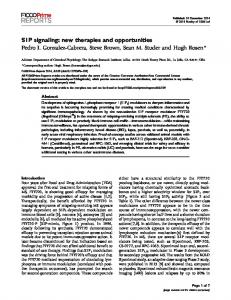
For the purpose of this discussion, a signaling protocol establishes, maintains and deletes state in a number of nodes which end-to-end flows traverse. State manipulation can either be done in a “soft” or in a “hard” way. SS7 and ST-II are example signaling protocols using hard state. Hard state refers to a state created in the network which can only be removed upon receiving an explicit tear-down message for deletion, while soft state refers to a nonpermanent state which will expire unless refreshed. In comparison to hard state signaling, soft state signaling is preferred as it provides better robustness in case of network situation changes, allowing the end-to-end communication to recover to a desired configuration without the need to send explicit messages. The soft state concept was introduced with the RSVP protocol originally designed for Internet QoS signaling, particularly for the IntServ QoS model [6]. The basic operation of RSVP can be illustrated as follows. As shown in Fig. 1, the host transmits the PATH message to the unicast or multicast group address(es) of the receiver(s), which conveys the sender information and its data flow characteristics (TSpec). The PATH message, which is encapsulated in a raw IP or UDP datagram with a Router Alert Option, is sent through all the routers along the path of the data flow, and at each RSVP router the RSVP process intercepts it, and creates a PATH state. This state allows response messages to travel backwards along the previously established path. Upon receipt of the PATH message, a RESV message is sent back toward the sender following the same path in the reverse direction, requesting the necessary resources (such as guaranteed bandwidth) for the data flow (FlowSpec). The data receiver authorizes the QoS reservation in the RESV message. Each RSVP router attempts to establish and maintain a RESV state to provide the requested service upon the receipt of the RESV message. Both PATH and RESV states are soft: PATH and RESV messages are sent periodically by hosts and routers to maintain these states, otherwise they will time out. The established state can be removed when the end host 3
Routers learn: •
PATH R 1
PATH messages sent periodically to refresh softstate.
•
PATH
PATH
R
PATH
2
R R
PATH
the path followed by packets from this source to this group. The TSpec for this sender.
PATH
4
3
(a) RSVP PATH messages sent by sender(s) Routers:
RESV RESV messages sent periodically to refresh softstate.
•
R 1
RESV R
RESV RESV R
•
Determine if RESV can be fulfilled according to RSpec. Forward/merge RESV
RESV RESV
2
R 4
3
(b) RSVP RESV messages sent by receiver(s) Fig. 1. RSVP basic operation
sends an explicit tear-down message after the application has finished sending the data. The end host may also rely on the soft-state timeout. RSVP does not rely on specific routing protocols and adapts to multicast group membership changes. It is possible to reuse RSVP for general-purpose Internet signaling. In fact it has been extended for many signaling purposes other than Internet QoS, such as label distribution for traffic engineering with RSVP-TE [7]. It has to be mentioned that the usage of RSVP in the domain of MPLS modifies some of the basic RSVP design principles and is as such not a classical application of path-coupled signaling. However, many intrinsic design limitations in RSVP have hindered its acceptance as a general-purpose signaling protocol, which motivated the introduction of a new framework. Some critical challenges are: Protocol complexity: First, the original RSVP makes per-flow reservations, requiring a pair of PATH and RESV state in RSVP routers that are indispensable part of the protocol operation, which is intended for the receiver-originated resource reservation purpose and optimized for multicast flows. This in turn requires a number of unnecessary objects and error handling for unicast data traffic. For the majority of signaling services which do not require multicast 1 , this only introduces overhead in protocol process1
According to http://www.multicasttech.com/multicast faq.html, the penetration of multicast in the Internet only accounts for a minority of less than 5% after nearly two decades development in multicast.
4
ing. Considering state overhead in each router is proportional to the number of data flows 2 , which requires non-trivial processing overhead. Although hop-by-hop reliability has been added later [9], in the basic RSVP specification [4], signaling messages are refreshed without distinguishing between message losses due to network congestion, route change or other message corruption. Thus, the reliability of signaling process has to rely on relatively long-term periodic refreshes, which makes it difficult to meet the requirements in all scenarios. Security: RSVP does provide basic security mechanisms with the RSVP Integrity Object [10] and with extensions for Identity Representation [11]. However, it does not allow standard security mechanisms, such as Transport Layer Security (TLS) [35] or IP Security (IPsec) [36], to be used because of the end-to-end addressing of a number of messages (e.g., PATH messages). Out-of-band key distribution is assumed and the selection of security association for end-to-end addressed messages is based on routing table lookups which is only useful in certain environments where the discovery nature of the end-to-end addressed messages is not meaningful. Some deficiencies can also be identified in the area of user authentication and authorization in roaming environments, primarily due to the interaction with COPS [12]. To the best of our knowledge, COPS has never experienced the same degree of deployment as Radius [13] or Diameter [14] and is therefore not regarded as an inter-domain AAA solution. For accounting and credit control COPS does not provide the adequate support and Radius or Diameter has to be used. Furthermore, the missing support for sender-initiated QoS reservations is not aligned with the common practice, where charging and pricing for the Internet service are often made for data senders. Mobility: RSVP was designed when node mobility had not yet matured. Unfortunately, even modest mobility introduces complications for RSVP [19,20]. For example, route changes and change of the end host’s IP address, are natural subsequences upon a mobile node’s movement. For downlink reservations (i.e., those with targeted data flow sending from the corresponding node to the mobile node), one has to rely on a next PATH refresh message, since a re-establishment of the RSVP routing path states can only be triggered by end-to-end addressed PATH messages. Furthermore, the flow identifier (flow ID) in RSVP, which is used to uniquely identify state in RSVP routers, consists of IP addresses and port numbers of sender(s) and receiver(s). According to Mobile IP [15,16], a mobile node will obtain a new IP address (care-of address) at the new point of attachment. Thus, a flow ID will be changed after a mobile node moves to a new location during an ongoing application session. Moreover, most IP mobility schemes introduce IP tunnels of some kind to allow the data traffic to reach the current location of the mobile node. To support these scenarios in RSVP is very challenging: 2
Aggregated RSVP reservations [8] allows coarser-grained state but the basic RSVP operations are the same.
5
even though some proposals attempted to extend RSVP for use in mobile environment (e.g., [18,19,17], to be shortly discussed in Section 3), there are still a number of open issues [25]. Extensibility: First, RSVP was designed to carry objects encoded in “TypeLength-Value” (TLV) opaque to QoS models. However, RSVP X-Specs (TSpec, FlowSpec, etc.) are mostly QoS-specific. There is no clear distinction between application-specific functions and general-purpose signaling functions. Second, signaling objects may vary in size – they can be fairly large, such as certificates, authorization tokens or active networking code. If a signaling message is too large and exceeds the link MTU, IP fragmentation is needed. This can lead to problems, e.g., in IPv6 where routers do not perform fragmentation. Thus, in RSVP, the messages size is limited by the MTU. Third, the overall design of RSVP was flat: all functionalities (reliability, soft-state, routing of signaling messages, multicast, etc) are integrated in single PATH/RESV messages. It was well-suited for Internet QoS signaling, but does not fit for general purpose signaling services. It is questionable whether a revised RSVP (with all the desired features included and others removed) should be called RSVP especially if it is not backward compatible anymore. We think that the changes are substantial enough to give the protocol (and the framework) a new name.
3
CASP – A FRAMEWORK FOR NEXT GENERATION IP SIGNALING
In order to meet some of the requirements listed in the previous section, e.g., mobility and extensibility, some attempts to adapt RSVP have been made. Some proposals, such as MRSVP (proposed by Talukdar et al. [17]), RSVP Flow Transparency (proposed by Shen et al. [18]), and Localized RSVP (proposed by Manner et al. [19]), attempted to resolve mobility issues with RSVP. For the convenience of the discussion in this paper we will refer to these types of approaches as “M-RSVP”. The basic idea is to introduce a mobilityindependent flow ID and thus after mobility takes place, a subsequent RSVP signaling procedure with the same flow ID will update established state information. Based on RSVP’s approach for receiver-initiated reservations authorization problems arise and also result in a long latency in re-establishing QoS states (see for example [20]). Furthermore, it is difficult to remove established states along the old path (most likely, only by relatively long-term state timeouts), whereas this is important for frequent path changes due to mobility. These approaches mentioned above address mobility but none of them demonstrates a greater extensibility in supporting various signaling services. There6
fore, recent research by Braden and Lindell [21] has attempted to separate its general signaling functionality from application-specific signaling functionalities, known as “Two-Level Architecture for Internet Signaling” (referred as “Two-level RSVP” hereafter). This approach makes a distinction between application-independent signaling services (referred as NSIS Transport Layer Protocol or NTLP in the NSIS terminology) and application-specific signaling services (provided by the NSIS Signaling Layer Protocols or NSLPs) to extend RSVP for general signaling. Work by Shore [22], Brunner and Greco [23], Westberg et al. [24] have developed some plausible system designs that demonstrate advantages based on Two-level RSVP signaling. In principle, all approaches described above can be categorized as filter-based approaches, which aim to perform signaling while discovering the next hop. However, due to the complexity and difficulty in supporting large signaling messages, mobility, congestion control and security, these approaches – which were directly derived from RSVP – failed to achieve wide acceptance, as pointed out during the NSIS analysis phase [25]. Therefore, we developed a new approach as an alternative to these approaches, the so-called Cross-Application Signaling Protocol (CASP) [26,27]. In comparison to filter-based approaches, CASP introduces the separation of discovery from signaling (herein referred as “discovery-based approach”), and a new control plane concept of “session identifier” to uniquely identify signaling sessions, unlike the flow ID used in RSVP, while maintaining some merits of filter-based approaches (e.g, “router-alert” way for next-hop discovery). The framework and protocols based on CASP concepts were developed and turned into a standardization track after CASP’s initial documents came out in September 2002.
3.1 CASP overview ... Next-Hop Discovery Client
NAT/FW Client QoS Client
Signaling Message Transport
Existing Transport Layer Protocol (e.g., TCP, SCTP, UDP)
Fig. 2. The CASP architecture
As shown in Fig. 2, the CASP architecture consists of 1) a generic messaging 7
layer, which transports signaling messages between the sender of the signaling session and the responder, as well as maintaining messaging layer state, and 2) a client layer, which consists of a next-hop discovery client and any number of specific signaling client protocols. The client protocols perform the actual signaling operations, such as QoS signaling and resource reservation, firewall/NAT configuration, or network diagnosis, where client data are carried in opaque objects. Typically, the initiator is the data sender and the responder is the data receiver, but CASP supports both sender-initiated actions, such as reserving resources, as well as receiver-initiated ones. The Scout protocol, a common discovery mechanism using RSVP PATH -like message with Router Alert Option, is introduced to actively determine next CASP hop along the path without bothering application functionalities. However, each node can choose its own next-hop discovery mechanism, relying on manual configuration, router advertisements, link state routing protocols, Scout or, for looselypath-coupled operation, server discovery solutions such as DNS, DHCP or SLP [28] when available, which in most cases could be more efficient than the Scout protocol. The process of discovering the next-hop NSIS aware node introduces security vulnerabilities that need to be addressed for each individual protocol. The security threats and the respective countermeasures of Scout are analyzed and discussed in [26].
Modern reliable transport protocols offer flow control, congestion control, fragmentation and reliability, which are important characteristics for a generic signaling protocol. For example, digitally signed messages or active networking code can be fairly large. Such large messages may need fragmentation and congestion control, which are the functionalities of TCP and SCTP [29], but not of unreliable transport protocols like UDP. Therefore, the CASP messaging layer is built on existing reliable or unreliable transport protocols, such as TCP, SCTP or UDP, depending on the needs of the application. Small, “oneshot” signaling messages can be embedded into the UDP or raw-IP discovery message for efficiency, while larger messages and reliable responses make use of a chain of reliable transport connections (TCP, SCTP). Naturally, the endto-end transport behavior may be determined by the weakest link. In many cases, depending on the number of imposed signaling sessions and the client layer refresh intervals, non-edge signaling peer nodes may communicate with each other with their client message exchanges before a transport connection expires and thus keeping their transport connections active for a long time, and avoiding the connection set up latency; if necessary (e.g., between non-edge neighboring CASP nodes, especially where route changes are more likely), the messaging layer can also have “keep-alive” soft state refreshes, without involving client layer. As a result, the average session setup latency is low. Furthermore, a messaging layer state teardown does not necessarily teardown the underlying transport connection, since it may be needed for a later session. 8
Unlike normal CASP messages, CASP Scout Request messages utilize UDP with a Router Alert Option [30,31] for its transport (like RSVP PATH messages). Although the destination of a Scout Request is the data receiver, the first CASP node with the desired client layer functionality along the path will respond (with a Scout Response) without forwarding it further on. Scout Requests have their own reliability mechanism. They are retransmitted periodically, with an exponentially increasing retransmission interval, which is a relatively small value.
3.2 CASP operation
A CASP messaging layer session is established between an initiator and a responder, along a chain of CASP nodes, with a cryptographically generated random session identifier (session ID) chosen by the initiator [53]. Additionally, a flow ID describes the data flow the signaling message pertains to. At each node, the CASP messaging layer remembers its previous CASP node, aside from the initiator. It also determines the next node along the data path, checks if there is an existing transport connection to that node; if not, establishes one, and then forwards the message downstream. The node then remembers the upstream node and associates it with the session identifier, a state refresh timer and a state expiration timer. This ensures that all messages for a session traverse the same set of CASP nodes, in both directions. The importance of the session identifier is described in Section 4.3. While delivering generic messaging layer signaling messages, the messaging layer establishes, refreshes, or releases states for signaling sessions; it also remembers the traversed path by installing state at individual routers (stateful approach) or records a route (stateless approach). Without requiring a CASP message to be delivered to the target, the CASP client layer decides whether a received CASP message needs to be forwarded on, or simply processed and/or responded with a feedback. Moreover, CASP utilizes a session identifier concept, which is a (probabilistically) unique and independent of flow sender or receiver. The session identifier is part of the signaling message and also the primary key to the messaging layer state, allowing proper operation in mobile environments (as it will be described in Section 4.3). Initiator
Router 1
Router 2
Responder
QoS Client
NATFW Client
QoS Client
QoS Client
Messaging Layer
Messaging Layer
Messaging Layer
Messaging Layer
Messaging Association
Fig. 3. An example of CASP signaling
Fig. 3 illustrates an example of CASP signaling where TCP is used as the 9
underlying transport mechanism (the SCTP case is similar; when UDP is used, a CASP message will be sent to a discovered next hop without checking or reusing any existing connection). The QoS signaling client of the initiator requests the CASP messaging layer to deliver its services from the initiator towards the responder. It is possible that some intermediate CASP nodes (in this example, Router 1) do not support the requested client layer functionality and the following operations take place: (1) The initiator creates a messaging layer session identifier, and determines that the next CASP node supporting QoS client is Router 2. The initiator triggers the Scout discovery process periodically by sending a Scout request towards the destination address. Router 2, in our example, will respond with a Scout response message. If there is an existing TCP connection between the initiator and Router 2 then a CASP message is generated and delivered to Router 2. (2) Upon receipt of the CASP message sent by the initiator, R2 passes its client payload on to the correspondent QoS client before forwarding the CASP message further. Additionally, it also remembers the previous hop. Router 2 might need to perform the same discovery procedure again. After determining that the Responder is the next hop to send CASP message, Router 2 establishes a TCP connection between itself and the responder, if no such TCP connection exists. (3) After the responder receives the CASP message and processes the QoS client data, it may need to return an acknowledgment to the initiator.
4
CASP DESIGN DETAILS
4.1 Application-specific signaling and extensibility under the CASP framework
Theoretically, CASP can support any number of application-specific signaling protocols (and discovery mechanisms). We developed two demanding applicationspecific signaling protocols, namely the QoS resource reservation client for CASP (CASP-QoS [32]) and the firewall/NAT signaling client CASP (CASPFW/NAT [33]). Based on services provided by CASP general signaling support, CASP-QoS intends to support QoS signaling functionalities provided by RSVP, while CASP-FW/NAT installs firewall pinholes and creates NAT bindings along the path. These clients have their own soft state but are not concerned with message transmission (such as dealing with packet loss, fragmentation and retransmission; these are handled by CASP messaging layer through the reuse of existing transport protocols). Before presenting these current signaling applications of CASP, we discuss the interactions between 10
these client protocols and the general signaling transport. Any signaling client can request general signaling transport services through a few primitives: ClientReq, ClientResp, and ClientNotification. In CASP, separation of a generic messaging layer from an application-specific client layer allows for any other signaling client protocols to be easily added. Each client only relies on common CASP signaling transport services and can be changed without affecting other clients. Furthermore, separation of a next hop discovery functionality from the messaging layer allows easier security protection of signaling procedures, and avoids complexity in messaging layer. This also helps to remove the restriction on the application signaling protocol, such as message size to be limited to MTU or introducing lower-layer overhead. Each client signaling application or discovery mechanism is identified by a type to be registered with IANA, and then used; this is much like RSVP object definition but allows a better extensibility due to its more modular design. As the first signaling application supported by the CASP framework, CASPQoS supports both sender-initiated and receiver-initiated reservations, mostly designed for unicast communications. It defines five message types: Query, Commit, Reserve, Release, Response, each of which may contain several objects in TLV format, including bandwidth, partial reservation, IntServ Flowspec, etc. The combination of “Reserve-Commit” makes a typical reservation: after a Reserve message determines whether the resources along the data path are available for reservation on behalf of a flow, a Commit message will make the actual reservation. However, the Commit message can either immediately be initiated by the responder and follow the reverse chain of nodes that the Reserve message traverses, or initiated by the initiator (after it receives a Response). Once created, QoS reservations are maintained as soft state: they will expire unless receiving periodical Reserve messages for refresh. In general, a Response message can be an answer to a Reserve or Commit message, and reports the result of these operations. In addition, the initiator can use a Query message to find out whether resources are available at any time along the CASP-QoS node chain, from the received Response message. An example message flow for CASP-QoS operation is shown in Fig. 4. The second signaling application after CASP-QoS is CASP-FW/NAT [33]. It allows nodes to signal information to firewalls, or to establish a NAT binding, as well as to provide the signaling initiator with the NAT information, and supports both sender-initiated and receiver-initiated operations. It defines six message types: Path, Create, Release, Response, Query, and Trigger. A Create message allows to establish or update FW/NAT state (e.g., flow ID, such as source/destination address, port number, transport protocol, SPI, etc.) upon a successful authorization and verification of the security policy. If the verification fails, a Response message with error indication is returned to the requesting entity. In the receiver-initiated operation, a Path message is used 11
Router 1 CASP-QoS
Initiator
Non-CASP router
Router 2 CASP-QoS
Responder
Query Response Reserve
refresh
Response Commit
Reserve
Response Commit
Fig. 4. An example of CASP-QoS operation
as a trigger for the responder to issue a Create message, whereas a Create message can be issued alone without a path trigger in a sender-initiated operation. A FW/NAT device can send an asynchronous event notification – the trigger message – to the end node. In addition, a Query message provides diagnostics functionality for the initiator to look up FW/NAT state along the path with the received response message. A typical example of CASP-FW/NAT operation with regard to receiver-initiated firewall signaling is illustrated in Fig. 5. Initiator
FW 1
Other routers
FW 2
Responder
Path: PF=(src= 139.23.203.23, dst=17.12.23.5, sport=5000, dport=600)
refresh Create: PF=(src= 139.23.203.23, dst=17.12.23.5, sport=5000, dport=600)
path
create
query response
Fig. 5. An example of CASP-FW/NAT operation
Message format for the CASP protocol suite can be found in Appendix. 4.2 General signaling transport
As depicted in Section 3.1, we can view the signaling architecture in CASP as three distinct parts: CASP messaging layer, the CASP client layer and the specialized client responsible for next hop discovery. In this section we present the CASP messaging layer and the Scout protocol for next hop discovery, which comprise the key functionality of general signaling transport and use of the following three types of messages: 12
Scout request (ScoutReq), which contains a router alert option and requested application type and will be processed (and by replying a scout response) if a CASP node receiving this message supports the given application type; Scout response (ScoutResp), which indicates the information about discovered next hop (IP address, etc). CASP signaling message (CaspMesg), which carries a session ID and other information (such as flow ID) for routing messages towards the responder, as well as an ADD/DEL flag indicating to install or remove state; Furthermore, there are several internal messages within the CASP general signaling transport mechanism, namely Discovery request (DiscReq), and Discovery response (DiscFail and DiscSucc). In order to provide enough robustness, the general signaling transport mechanism in CASP supports soft state in reacting to changes of network situations (for example, see Section 4.3 for discussions on route change and mobility cases). The state in messaging layer indicates the delivery path of a given session, uniquely identified by a session ID. Additionally, associated with a soft state there are two types of timers: a refresh timer in signaling initiator whose expiration triggers a refresh of soft state along the path; and a state timer in all participating CASP nodes which controls the expiration of the soft state. Fig. 6 and 7 depicts the finite state machines for the general signaling transport mechanism provided in CASP. The scout protocol has only two general states: Idle and WaitResp (waiting for scout response), whereas the messaging layer keeps track of much more complex states: Idle, WaitDisc (waiting for discovery success), NHopDiscd (next hop is discovered but state not established), and Established. Their transitions with different event triggers show how the CASP signaling transport defined in [26] may be implemented. However, implementers can build their own CASP signaling systems and choose their own way of internal processing of CASP messages and interfacing with applications using CASP.
ClientReq, CaspMesg
RefreshTimerExp StateTimerExp CaspMesg
DiscFail DiscSucc
Init
Idle
ClientReq, CaspMesg
WaitDisc
StateTimerExp CaspMesg
NHopDiscd
Established
NHopTimerExp
Fig. 6. CASP messaging layer state machine
13
DiscReq
Init
RetryTimerExp RetryTimerExp, ScoutResp
DiscReq
Idle
WaitResp
Fig. 7. CASP Scout protocol state machine
4.3 Mobility support in CASP
By its intrinsic design, CASP signaling supports route change and mobility scenarios, due to the introduction of a unique session ID that is independent of source and destination IP addresses, the extensible discovery component, and additional a Branch ID which identifies the changed signaling path segment. A CASP node use a counter for the Branch ID, incrementing it by one when a new branch occurs. A node needs to be able to determine which branch is the “most up-to-date” one. Branch IDs typically are just “locally” meaningful, not necessarily end-to-end. DEL B