Beyond Secure Channels Yacine Gasmi
Ahmad-Reza Sadeghi
Patrick Stewin
HGI – Ruhr-University Bochum Universitätsstraße 150 Bochum, Germany
HGI – Ruhr-University Bochum Universitätsstraße 150 Bochum, Germany
HGI – Ruhr-University Bochum Universitätsstraße 150 Bochum, Germany
[email protected] [email protected] [email protected] Martin Unger N. Asokan HGI – Ruhr-University Bochum Universitätsstraße 150 Bochum, Germany
[email protected]
Nokia Research Center P.O. Box 407 Helsinki, Finland
[email protected]
ABSTRACT
1. MOTIVATION
A Trusted Channel is a secure communication channel which is cryptographically bound to the state of the hardware and software configurations of the endpoints. In this paper, we describe secure and flexible mechanisms to establish and maintain Trusted Channels which do not have the deficiencies of previous proposals. We also present a concrete implementation proposal based on Transport Layer Security (TLS) protocol, and Trusted Computing technology. We use Subject Key Attestation Evidence extensions to X.509v3 certificates to convey configuration information during key agreement (TLS handshake). The resulting session key is kept within the Trusted Computing Base, and is updated in a pre-determined manner to reflect any detected change in the local configuration. This allows an endpoint to detect changes in the configuration of the peer endpoint while the Trusted Channel is in place, and to decide according to a local policy whether to maintain or tear down the Trusted Channel.
The number and types of digital services available over the Internet continue to rise. Examples include online banking, e-commerce and e-government services, and content delivery. The ability to enforce access control is crucial to the security of many of these services. Since the Internet is an open network, access control is based on establishing secure communication channels that assure confidentiality, integrity, and freshness of the transmitted data as well as authenticity of the involved endpoints. The standard approach is to use communication security protocols like Transport Layer Security (TLS) [4] or Internet Protocol Security (IPSec) [9]. However, these protocols do not provide any guarantees about the integrity of the endpoints. Nodes on the Internet are subject to constant attacks from malicious software. Compromised endpoints on the Internet is a fact of life. Security breaches on the Internet today rarely involve compromising the secure channel because endpoints are much easier to compromise. Using a secure channel to an endpoint of unknown integrity is ultimately futile; In the words of Gene Spafford, “using encryption on the Internet is the equivalent of arranging an armored car to deliver credit card information from someone living in a cardboard box to someone living on a park bench”[19]. To meet the security needs of digital services over open networks, we need a way of establishing a communication channel which provides a way for an endpoint to securely obtain information about the state of the hardware and software configuration of the peer endpoint to verify whether this state is trustworthy, i.e., whether it conforms to a locally defined security policy. To determine the trustworthiness of an endpoint, information regarding its state and behavior is needed. Reporting integrity information of a remote platform is one of the main goals of Trusted Computing (TC) as proposed by the Trusted Computing Group (TCG). The basic idea is to securely measure integrity information or fingerprints of the core components of the platform (firmware and software) during the startup process. This information is stored in a cost-effective, tamper-resistant Trusted Platform Module (TPM). This module is mounted on the mainboard of the computing platform and acts as trust anchor. It can sign the measured integrity information and report it to a requesting party.
Categories and Subject Descriptors C.2.2 [Computer-Communication Networks]: Network Protocols—Applications (SMTP, FTP, etc.); C.2.4 [Computer-Communication Networks]: Distributed Systems —client/server
General Terms Security
Keywords Relay Attack, Remote Attestation, State Changes, TLS, Trusted Channel, Hypervisor, Microkernel, Trusted Computing, Virtualization
Permission to make digital or hard copies of all or part of this work for personal or classroom use is granted without fee provided that copies are not made or distributed for profit or commercial advantage and that copies bear this notice and the full citation on the first page. To copy otherwise, to republish, to post on servers or to redistribute to lists, requires prior specific permission and/or a fee. STC’07, November 2, 2007, Alexandria, Virginia, USA. Copyright 2007 ACM 978-1-59593-888-6/07/0011 ...$5.00.
Our target is to use general purpose platform rather than secure co-processors. If we validate the platform configuration only at session setup, then, in order to prevent bait-andswitch attacks we must prevent any configuration change while the session is active. This may be problematic in general purpose systems because multiple simultaneous applications have to co-exist on them. The problem becomes particularly severe in contexts where long-lived TLS sessions are used (e.g., [18]). Therefore we need to allow configuration changes, but still retain the ability to verify them. Main Contribution: In this paper we propose a security architecture and mechanisms for establishing and maintaining a Trusted Channel. It combines the TLS protocol with the platform integrity measurement and reporting features of TCG Trusted Computing functionalities. Linking endpoint integrity information to secure channels has been already investigated in the literature (cf. [6, 20, 15, 10, 8]), in particular in conjunction with the TLS protocol that is well-known and often deployed in practice. Also the TCG is addressing this issue (cf. [22, 27]). However, none of the solutions so far addresses the problem fully. Some are specified in insufficient detail, e.g., [15] do not explain how they exactly establish the linkage to TLS. Others have deficiencies regarding security or trust assumptions that we do not have: e.g. [20] aims to prevent relay attacks, but as shown in Section 4, these attacks seem still possible. [6] have the same problem without stronger trust assumptions. However, almost all approaches attempt to verify the integrity of a platform only at the time of setting up the secure channel and most of them do not consider mutual security. Our proposal avoids the shortcomings of the previous proposals. It (i) provides the security properties required for a secure communication channel, (ii) allows the peers to cryptographically bind measurements of the endpoint configurations to the secure channel, (iii) provides the means to force any change in the configuration of one endpoint to be reported to the peer while the channel is in place, and (iv) minimizes the information disclosed to the peer or third parties. We propose a concrete implementation of our solution based on the TPM. Outline: In Section 2 we define the basic terms, describe a high-level protocol for Trusted Channels, and consider the security properties to be provided by Trusted Channels. In Section 3, we propose an implementation of our Trusted Channel protocol based on the TLS protocol and the TPM. Related work is elaborated in Section 4. Finally, in Section 5, we briefly present security considerations regarding the requirements in Section 2.
2.
TRUSTED CHANNEL
The underlying security architecture considers client C and server S communication where each involved endpoint may require information about the state of the other endpoint. The evaluation of state information is done according to the locally applied security policy. If the endpoint state information conforms to the security policy the corresponding endpoint is considered to be trustworthy.1 This security policy consists of a set of requirements and guidelines that have to be fulfilled by the platform configuration 1
There exist several approaches how trustworthiness may be determined (e.g., [13]). How this is done exactly is out of scope of this paper.
of the counterpart, e.g., that an appropriate access control enforcement mechanism is in place, etc. In the following we first describe a high-level protocol for the establishment of Trusted Channels followed by security requirements.
2.1 Basic Definitions The communication endpoints operate based on components called compartments. A compartment is a software component that is logically isolated from other software components. Isolation means a compartment can only access data of another compartment using specified interfaces provided by a controlling instance. The configuration of a compartment describes the compartment’s I/O behavior. The process of deriving/determining the configuration of a component (hardware and/or software) is called measurement conducted according to a well-defined metric (e.g., by deriving a fingerprint of its code). The resulting measurement value represents the component’s state and behavior and can be used as a means for deciding on trustworthiness. The set of all security crucial components of a platform responsible for preserving its trustworthiness is called Trusted Computing Base (TCB). The TCB is considered trustworthy by definition. Hence, the main goal of system design is to keep the TCB as small as possible. In Section 3 we show the corresponding TCB components of our architecture.
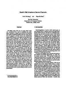
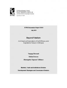
2.2 Establishing a Remote Trusted Channel We differentiate between Local and Remote Trusted Channels. The former designates a channel between compartments running on top of the same TCB while the latter concerns compartments running on different TCBs. Note that for local channels the validation of the TCB’s trustworthiness is redundant. In this paper we focus on the establishment of Remote Trusted Channels. These channels are fully controlled by the TCB. Basically, the TCB generates and maintains the required keys and establishes a channel to a remote party through a potentially untrusted Communication Software CS . Since the protocol has symmetric structure we omit superscript C and S in the following text. The central idea is to make sensitive channel information such as credentials and secret keys only accessible to the desired/trustworthy TCB and not to CS or client compartments. Binding this information to the TCB assures that the establishment and use of the channel is only possible by the platform’s TCB, that later reports the configuration of the client compartments to the other peer. CS only manages the transport of protected data. The setup of a Trusted Channel starts with a handshake protocol as shown in Figure 1. We split the protocol flow into the following phases. In phase 1, Negotiating Security Parameters, both parties negotiate which side has to report on its configuration information. Additionally, an encryption key Kenc of a secure encryption scheme (here an asymmetric encryption key pair Kenc := (PKenc , SKenc )) is generated at any time before the handshake begins and now used for credential exchange. Kenc is bound to the TCB configuration confTCB . As consequence the private part SKenc is only available if the TCB has that specific configuration. A certificate issued by a trusted authority confirms this fact. Both sides exchange this certificate cert which includes the corresponding public part PKenc and confTCB which is evaluated by both sides. The exchange of confTCB at this early stage allows both sides to evaluate the trustworthiness of the
Figure 1: Establishing Remote Trusted Channels counterpart’s TCB. Furthermore configuration information conf that reflects the actual state of compartments involved in the communication is encrypted using PKenc , and the result encC is sent to the counterpart. In phase 2, Configuration Exchange, encC is received and the local configuration conf of the recipient is sent back encrypted to the counterpart. At both sides the corresponding CS forwards encC to the TCB. The exchange of conf allows both sides to evaluate whether the actual configuration of the peer’s compartments conforms to their security policy or not, in phase 3, Configuration Validation, before sending sensitive data. In phase 4, Secure Session, the TCB finally computes the session key KS and returns only a handle2 to CS . For finishing the handshake a key confirmation message is sent to be sure that both sides have computed the same KS .
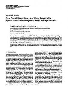
Updating session key after state change. We do not prevent state changes to appear in compartments during a communication session.3 Whenever the state of the platform changes while a Trusted Channel is in place, access to sensitive data such as KS can be restricted according to application requirements. Subsequently, KS has to be updated. It must be guaranteed that each side is notified about the new state conf ′ . Figure 2 gives a high-level view of the update protocol. The possibility of barring access to KS is guaranteed by keeping it in the TCB and giving only a handle to CS . For notifying the counterpart about conf ′ the TCB updates KS to KS′ in phase 1, Notifying State Change. If demanded by the application, access to the old KS and received data may be prohibited to CS and the client compartments. Hence, to be able to continue communication the counterpart has to be notified about conf ′ to update KS to KS′ as well. The important issue here is that a malicious CS cannot conceal any state change because KS is updated and access to it can 2 A handle is a kind of identifier used by CS to notify the TCB which key it has to use for decryption. 3 The state of the TCB is not allowed to change during a session.
be barred. The TCB informs CS about KS′ and sends encC ′ to the other peer. Since the Trusted Channel is still existing between the involved TCBs, KS is used, in phase 2, Updating Session Key, for transmission. Instead of performing a full key exchange, both sides only update the session key in a predefined manner. Thus, the other side decrypts encC ′ , validates conf ′ and decides whether the new state is acceptable or not. If conf ′ is acceptable, KS is updated to KS′ and the communication continues as before after successful key confirmation. Otherwise, the endpoint simply breaks the connection and data on the other endpoint may be deleted or stored by the TCB depending on the application.
2.3 Requirement Analysis In this Section we informally consider the security objective and properties of a Trusted Channel. The objective for each party is to create and maintain a secure communication channel to a certain trustworthy entity and within a certain peer endpoint such that no other untrusted entity, either between the two endpoints, or within the peer endpoint can violate the security of the channel. More concretely, a Trusted Channel (we adapted the definition of [15]) (i) provides the security properties required for a secure communication channel, (ii) allows the peers to cryptographically bind measurements of the endpoint configurations to the secure channel, (iii) provides the means to force any change in the configuration of one endpoint to be reported to the peer while the channel is in place, and (iv) minimizes the information disclosed to the peer or third parties. Thus, we require the following properties for a Trusted Channel: (R1) Secure channel properties: Integrity and confidentiality of data, freshness to prevent replay attacks, and authenticity both during transmission as well as within the endpoints have to be provided. (R2) Authentic linkage of configuration information and secure channel: Configuration information has to be delivered to the communication partner authentically at the establishment and while the Trusted
Figure 2: Update of KS and notification of the counterpart
3.1.1 TC-enabled Hardware Layer
Figure 3: Layered Architecture
Channel is in place. Authenticity of this information is important to prevent relay attacks where the configuration of a trustworthy third platform is relayed by an attacker, acting as Man-In-The-Middle, to cheat the requesting party. Providing configuration information during the communication implies reporting any state change on the involved platforms. (R3) Privacy: Creation and maintenance of the channel should adhere to the least information paradigm, i.e., disclosure of platform configuration information does not go beyond what is necessary for proper validation. Further platform configuration information has to be protected against disclosure to a third party.
3.
IMPLEMENTATION
In this section we briefly explain the implementation of the underlying security architecture for establishing Remote Trusted Channels. Our approach is based on [15] where the concept of Trusted Channels is used in a DRM scenario. However, we propose a detailed implementation of a Trusted Channel based on TLS protocol, which is one of the most commonly deployed secure channel protocols, rather simple and enabling interoperability.
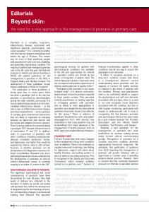
3.1 System Architecture Our system architecture is shown in Figure 3. It is based on security frameworks as proposed, e.g., in [14], [16], and consists of an Application, Trusted Service, Virtualization as well as TC-enabled Hardware Layer 4 .
The hardware platform has to provide additional components as defined by the TCG in various specifications (e.g., [23]). The central component forms the TPM which is currently implemented as a dedicated hardware chip. It offers amongst others a cryptographic hash function (SHA1), a cryptographic engine (RSA) for encryption/decryption and signing, a hardware-based Random Number Generator (RNG), hardware protected monotonic counters as well as some amount of protected storage. It provides a set of registers in protected storage called Platform Configuration Registers (PCR) that can be used to store hash values. Protection mechanisms ensure that the value of a PCR can only be modified in a predefined way5 (see also Section 3.2). Protected storage is also used to store certain security sensitive keys, e.g., Attestation Identity Keys (AIK). An AIK is non-migratable, i.e., its private part never leaves the TPM’s protected storage and can only be applied for signing data (e.g., via the TPM Quote() command) that originates from the TPM but not for encryption (cf. [23, p.18]). An AIK certificate certAIK can be obtained from a Certification Authority (CA) that vouches for the mentioned AIK properties. Furthermore the TPM provides functionalities such as binding and sealing that allow to cryptographically relate/bind data to a certain platform configuration, which is reflected by a subset of PCR values. The TCG attacker model considers software attacks. Thus, it is assumed that a TPM is only vulnerable to hardware attacks.
3.1.2 Virtualization Layer The Virtualization Layer is part of the TCB and consists of a hypervisor. We use a L4 microkernel but we kept the interfaces generic so that Xen could also be considered (cf. [16]). The hypervisor provides and mediates access to hardware components of the platform by presenting virtualized instances of these components to the upper layers. Additionally, it offers fundamental functionalities like scheduling, memory management and interrupts. By providing virtual memory that solely directs memory accesses to logical address spaces, interfaces for access control mechanisms and monitored Inter Process Communication (IPC) the virtualization layer guarantees separation of compartments (run5
4
The term TC-enabled is further used with regard to platform conform to the TCG specifications.
PCR i+1 ← Hash(PCR i |x), with old register value PCR i , new register value PCRi+1 , and input x (e.g., a SHA-1 hash value). This process is called extending a PCR.
time isolation).6 The code of the TCB resides in a protected memory region and is only accessible to higher layers by using specific interfaces. Additionally, only trusted software runs in kernel mode. All device drivers and compartments in turn run in user mode. Thus, separation from software layers operating on top of the virtualization layer is also guaranteed.
3.1.3 Trusted Service Layer This layer consists of security services and provides interfaces to the Application Layer. These interfaces allow applications to use enhanced security functionalities strengthened by Trusted Computing. It also mediates and monitors access to virtualized hardware resources. Thus, this layer enforces isolation of compartments and controls communication between processes running in different compartments. The following services are the main components of the TCB in our approach: • Trust Manager (TM) provides functionalities used for establishing Trusted Channels. The corresponding keys are computed and held by TM. They never leave the TCB, only key handles of the session keys are passed on to the Application Layer. The usage of TPM functions (cf. Section 3.1.1) is restricted to code running in kernel mode. This is ensured using the TPM concept of localities (see [24, p.7]) and TM controlling access to the TPM interfaces. Furthermore, TM allocates memory for transferred data and controls access to it according to an application security policy. • Compartment Manager (CM) measures compartments when starting them. To differentiate client compartments, CM assigns a unique ID to every compartment. The compartment’s configuration is appended together with its ID in a Configuration Data Structure (CDS). CM takes care of keeping CDS secure (inside the TCB) and providing it to other TCB components. CM acts also as a monitoring agent. Thus, every state change of a running compartment will be noticed. An implementation of the monitoring agent is in progress. Approaches such as the Integrity Measurement Architecture proposed in [17] may be incorporated in our architecture but must be adapted accordingly. • Storage Manager (SM) handles persistent data storing. It guarantees trusted storage, i.e., availability, authenticity, confidentiality as well as integrity of the stored data. When data is stored freshness can be guaranteed using the monotonic counters of the TPM. Additionally, trusted storage provides isolation of stored data from different compartments by cryptographic means. By using PCR values SM can seal data to a platform configuration. Thus data decryption is only possible if a specific platform state is present (cf. [26, p.44-52]).
3.1.4 Application Layer Our architecture comprises a compartment used to establish a TLS channel for other compartments.7 It runs a TLS 6 Direct Memory Access (DMA) is not considered here. To protect against attacks misusing DMA new security concepts like Intel Trusted Execution Technology (TXT, cf. [7]) or AMD I/O Virtualization Technology, (cf. [1]) have to be applied. 7 It is also possible to integrate the TLS software into communicating compartments, but for modularity reasons and
software that is able to interpret TLS extensions designed for our approach (for TLS extensions cf. [5]). TLS adaptations: The introduced adaptations consist of TLS extensions (state change extension , binding extension) transmitted within the ClientHello or ServerHello messages and include important information for the handshake protocol. Furthermore, we extend the existing TLS messages ServerKeyExchange and ClientKeyExchange to optionally include CDS . We also adapt the session key computation to include this CDS and introduce a new cipher suite. Remote attestation: We enhance the TLS handshake protocol to exchange configuration information for performing a remote attestation. There are several approaches to attest to the configuration of a platform, e.g., the TCG remote attestation approach, where the configuration is captured by computing and collecting fingerprints for every hardware and software component, or property-based attestation, where the remote platform only attests to certain security properties of the platform (see [13]). We adapt the TCG concept by using a mixture of both approaches and dividing the remote attestation into two parts. At first both peers provide certificates (certbind , certAIK , see below) included in binding extension, that vouch for the secret part of the key to be used for the transfer of secrets in the handshake being sealed to a specific TCB configuration.8 The partners evaluate if the TCB of the counterpart adheres to their respective security policy by checking the TCB’s fingerprint against a reference value provided by a trusted third party. In a second step we exchange configuration information based on properties as well as fingerprints that is related to the compartments involved in the communication. This information represented by CDS comprises an accumulated hash value of the TCB and includes the compartment configurations. The entries of the counterpart’s CDS are checked against a specific application security policy by either comparing the received fingerprints against reference values or, e.g., checking certificate chains that vouch for certain properties. Negotiating Attestation Type: During our extended handshake, the endpoints negotiate which side (C and/or S) has to attest to its state, i.e., the type of attestation supported (mutual, client-sided, server-sided) by evaluating binding extension.
3.2 Trusted Initialization To be able to attest to a platform’s configuration its hardand software components have to be measured reliably and those measurements have to be stored securely. An ongoing measurement process is effected originating from the Core Root of Trust for Measurement 9 that initiates the measurement process up to the Application Layer. Every component that has to be loaded during the boot process is measured before passing control over to it. Consequently, a Chain reusability we chose to provide a separate compartment for TLS software. 8 certbind has to be sent via binding extension, because PKenc included in certbind is needed at this early stage to encrypt configuration information. The Certificate message (cf. [4, p.40ff]) could also be used if a new TLS message after ClientKeyExchange for sending configuration information from S to C was introduced. 9 A small piece of code initiating the measurement process at the very beginning of the boot process. Usually this code is located within the BIOS.
of Trust is established and the TCB is measured reliably. These measurements consisting of hash values over loaded code are stored in PCRs and represent the static configuration in our approach because it must be only modifiable with a following reboot. After the boot process platform monitoring is conducted by CM. CDS that reflects the platform configuration is maintained by CM. CDS represents the dynamic configuration because we allow state changes to happen. Thus, these compartments at the Application Layer are not deemed entirely trustworthy, they are monitored and if their state changes (e.g., a library is loaded) their trustworthiness has to be reassured by the peer via checking the new configuration with respect to its security policy. In our approach the Chain of Trust is initially built up to the TCB. Subsequently, CM extends the Chain of Trust when a client compartment as well as the TLS software compartment are loaded. Afterwards the system is initialized and ready to build up a Remote Trusted Channel.
3.3 Handshake In this Section we describe the linkage of integrity reporting to the TLS protocol. To be able to set up a Trusted Channel we define the following credentials: Attestation Encryption Key (Kenc ): We introduce the asymmetric Attestation Encryption Key (AEK) Kenc , that is considered long-lived and usable for all client compartments that wish to establish a Trusted Channel to a remote party. It is created and sealed by TM at any time before the Trusted Channel is set up. Kenc is loaded during boot time and kept inside the TCB. The public part PKenc is sent to the counterpart instead of a public TLS key to transfer secrets during the handshake. Binding Key (Kbind ) and Binding Certificate (certbind ): The long-lived asymmetric key pair Kbind is created using the command TPM CreateWrapKey() at any time before a Trusted Channel is set up and after an AIK but before Kenc is generated. Its private part SKbind is sealed nonmigratable to a specific TCB and never leaves the TPM unencrypted. We make use of the Subject Key Attestation Evidence (SKAE) as proposed by the TCG (cf. [21]). SKAE provides a certificate extension for X.509v3 certificates certified by a CA vouching that Kbind was created by a Trusted Platform that conforms to the TCG specification (cf. [23]) and that a certain TCB configuration has to be in place during release, by signing it with an AIK using TPM CertifyKey().10 We include the SKAE extension in a binding certificate certbind that replaces the TLS certificate and authenticates the endpoints. We need Kbind for authenticating Kenc :11 By signing PKenc using SKbind we provide evidence that SKenc is kept secure inside the same TCB.12 To use an AIK is not allowed for this purpose. We use 10
The SKAE extension centrally consists of a TPM_CERTIFY_INFO2 structure containing PCR values that have to be in place during key release and a digest of PKbind (cf. [25, p.96]). Furthermore a signature over TPM_CERTIFY_INFO2 that was created using an AIK is also included in the extension. 11 It is also possible to use Kbind instead of Kenc for encryption during the handshake. But the involvement of the TPM every time a Trusted Channel is set up when using Kbind would result in performance loss. 12 The TCB must check digest at creation and digest at release (cf. [25, p.89]) before signing PKenc with SKbind .
TPM Sign() to sign Kenc ’s public part PKenc . The resulting signature and PKenc represent a further certificate extension AEK extension that is also included in certbind . certbind may be signed by a CA or by the TCB. We do not impose restrictions on the design of the certificate apart from the inclusion of a SKAE extension and our AEK extension as shown in the following: certbind := { serial no, issuer, subject, PKbind , TPM_CERTIFY_INFO2, sign{TPM_CERTIFY_INFO2}SKAIK , | {z } SKAE extension
P Kenc , sign{P Kenc }SKbind , {z } | AEK extension
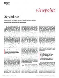
sign{certbind }SKCA } Figure 4 shows how these credentials are used in the protocol flow between the two parties involved in the communication with focus on the client TCB. Principally, the message flow among the TCB components is similar for C and S depending on the kind of attestation chosen (mutual, serversided, client-sided). For better understanding we use the protocol phases introduced in Section 2.2. Negotiating Security Parameters: A compartment with the identity compID starts TLS C using CM C . Then TLS C issues init() to TM C to indicate that a TLS connection using the attestation feature is desired by compID. The session context SC is created by TM C which stores all data related to the Trusted Channel session sessionID . A random generator that provides rd C is seeded using TPM GetRandom() at C C boot-time. Additionally, certbind and certAIK are provided C C by TM C calling SM C . rd C , certbind and certAIK are stored C C in SC .13 A nonce nonce C , certbind and certAIK are then returned to the TLS C as parameters for the ClientHello mesC C sage, where certbind and certAIK are comprised in the attestation extension binding extension C included in the extension list hello ext list C (cf. [5]). Subsequently the ClientHello message is transmitted to S. Analogously, the ServerHello message is sent to C. Configuration Exchange: TLS S requests an Attestation C C Blob AB S . certbind and certAIK are verified and the TCB configuration of the respective counterpart is validated. If this evaluation fails communication is aborted issuing a corresponding TLS alert (cf. [4]). Otherwise AB S is created by TM S . It consists of key material rdSessionKey S , CDS S C 14 and nonce C encrypted using PKenc . CDS S is reliably provided by CM S . nonce C is included to ensure freshness and rdSessionKey S is later used to compute the master secret ms. CDS S is only added if the corresponding form of attestation has been chosen (mutual, server-sided). AB S is sent to C in the ServerKeyExchange message. The structure of this message has to be adapted to support this kind of key exchange including attestation. All actions taken for AB S are also applied on client side to create AB C . Configuration Validation: TLS C sends the received AB S C to TM C that decrypts AB S using SKenc . TM C now valiS C dates CDS and nonce to ensure the freshness of AB S . rd C is split in 28 bytes for nonce C and 48 bytes rdSessionKey C (KS key material). 14 In our approach we use a RSA-based key exchange, using Diffie-Hellman would also be possible. 13
If decryption or verification fails corresponding TLS alerts are issued. Otherwise a decision is made either to trust in the remote party or to cancel the session. If the remote party is considered trustworthy, rdSessionKey S is saved in SC and used later to compute ms. AB C is sent to S in the ClientKeyExchange message which is also adapted. On the server side AB C is verified analogously to AB S . Secure Session: TLS C gets a handle to the session key KS . KS is generated using the same ms on both peers. ms is computed using nonce C , nonce S , a string indicating that it is ms, rdSessionKey C and rdSessionKey S as input to a pseudo random function (PRF). Subsequently, TM C derives KS using ms, CDS S and CDS C (cf. [4, p.24]). KS is computed analogously on the server side. In the last step the TLS key exchange is completed and the handshake is finalized by the [ChangeCipherSpec] and a final Finished message. This message is already encrypted using KS , thus, a failure in key exchange would be noticed (cf. [4, p.51]).
State Change. A state change on one platform is noticed by CM (an efficient monitoring agent assumed, cf. Section 3.1.3). TM can restrict access to keys and data belonging to the session depending on the security policy. Both sides are notified using HelloRequest , ClientHello and ServerHello, respectively. The updated CDS ′ for validating the new configuration conf ′ and updating KS is securely transmitted to the counterpart encrypted using KS (since the Trusted Channel is still in place between the involved TCBs) and included in state change extension . Subsequently, a TLS resume message flow takes place (cf. [4]). For a detailed view of the state change protocol flow see Appendix A.
4. RELATED WORK
Figure 4: Protocol Flow with detailed client TCB
Establishing trust in client/server communication has already been examined in the past. E.g., [8] and [3] apply secure co-processors for running evaluated and certified guardian programs as trusted co-servers, that are used to authenticate the main servers reliably to monitor their behavior and to do sensitive computations. However, this approach relies on rather expensive co-processors that are more secure against physical tampering. We choose to use off-theshelf hardware for our approach. Moreover, [8] only consider the server-side. The client remains unmonitored. [10] use the TPM to induce trust into web applications. Their trust model is based on the mapping of a long-lived key pair to short-lived configurations. However, [10] use a huge TCB since their system is based on a Linux kernel. Furthermore, no isolation based on virtualization is guaranteed. Software compartments are realized using the very complex SELinux security module. Like in [8] the approach of [10] addresses only the trustworthiness of one peer. In addition, state changes while a channel is in place are not considered. The TCG is working on a Reference Architecture, that aims to standardize the management of platform configuration (cf. [22]). A specific use case of that architecture is called Trusted Network Connect (TNC, cf. [22, p.51]). However, the published specifications focus on network authentication and policy enforcement when granting network access only, but they do not consider state changes during the session. Furthermore, the TCG does not consider the linkage
between configuration information and secure channels. In [27, 15] they state that the exchange of integrity data “relies on the underlying network authorization transport protocol [...] to provide a secure authenticated channel”, but they also state that “TNC does not expect to standardize this protocol” (cf. [27, p.16]). The group is working on the TLS Extensions for Attestation (TLS-Attestation) Specification (cf. [22, p.51]) as standard for exchanging integrity data, but the document has not been published yet. However, our approach can also be applied to the TNC model. In [12] a security protocol is proposed that combines multiple facets of endpoint authentication, e.g., user and platform authentication, by introducing a two-phase handshake through TLS extensions. However, the application is rather generic and does not consider relay attacks or configuration changes in detail. Another proposal (cf. [11]) considers the capabilities of modern chipset architectures such as AMD SVM and Intel’s Trusted Execution Technology. The basic idea is to load only security-sensitive code pieces of an application instead of a VMM into an isolated secure exection environment. This idea seems to be very elegant since it reduces the size of the TCB drastically. However, the approach requires TPM involvement every time a session is initiated. This affects performance when a server has to set up many TLS connections. Furthermore, encryption and decryption of network packets is not performed in the trusted environment, i.e., an untrusted application obtains the session key. The central issue identified in the following related work is the necessity of a secure link between the secure channel and configuration reporting, in particular to prevent relay attacks. In [20] the authors present a solution where the Diffie-Hellman (DH) key exchange is bound to the integrity reporting information by incorporating the public DH key as external data in TPM Quote (cf. [20, p.9]). However, this approach is not secure against relay attacks. It is vulnerable to a Man-in-the-Middle (MitM) attack on the public DH key during Remote Attestation, because [26, p.157] explicitly allows to add external data (here the public DH key) to TPM Quote from a remote platform. A different approach to prevent relay attacks is proposed in [6]. Here, the SSL certificate (or public key) is added to the list of measured platform integrity values and can therefore be verified through the attestation. The link between SSL properties and platform integrity values is created by a Platform Property Certificate that contains, e.g., the domain name and is signed using the AIK. However, this approach needs to make stronger assumptions to prevent a MitM attack, because it is not clearly stated how to prevent that the respective PCR is extended with a SSL certificate (or key) that originates from another, malicious platform. As in [20], the attack seems especially realistic in the case that the malicious platform and the one attesting to its configuration colaborate. In our approach this attack is prevented by using a non-migratable key that is signed using the AIK. A second security concern of [20] is that by giving the session key to the communication software, key and transmitted data remain unprotected in case of a state change. Platform manipulation during session run-time could compromise data and keys and, hence, enable MitM attacks. Especially with regard to the chosen DRM scenario this appears critical. [6] in turn consider state changes in the sense that a channel is closed in this case. However, like in [20] it is not
stated how unauthorized access to already received data is prevented. In our approach session key and received data remain protected by the TCB. Access to the session key is denied until the new state has been approved by the counterpart. Furthermore, access to already received data is barred if required by the underlying security policy. Moreover, our concept provides more flexibility because the channel is not automatically aborted in case of a state change and communication can be continued after a re-evaluation of configuration information. The approach in [15] is related to the one presented in this paper. However, it does not consider mutual attestation and uses key transport rather than contributory key agreement. In contrast we consider mutual attestation as well as contribution of key material by both parties involved. In all the mentioned approaches configuration information is sent in plain text, which raises privacy and security concerns. Our approach assures that configuration information is always transmitted in encrypted form to a verified TCB at the peer.
5. SECURITY CONSIDERATIONS TCB and TLS protocol provide certain security properties. The main security properties provided by the TCB are platform monitoring including trusted initialization, Local Trusted Channels, strong isolation, trusted storage and protected storage. TLS security properties have been already considered in numerous research papers (e.g., [28]). Thus, we assume that TLS prevents attacks like, e.g., version rollback ([28, p.9]), ciphersuite rollback (cf. [28, p.6]), replay or short-block attacks (cf. [2]) with regard to the secure channel during transmission. In the following we discuss that our channel fulfills the requirements (cf. Section 2.3). (R1) Secure channel properties: TLS provides secure channel properties during transmission over insecure networks. On the endpoints the TCB offers those properties. Confidentiality and integrity are provided by trusted initialization, strong isolation of the TCB and platform monitoring. The TCB also takes care of authenticity and freshness by securely storing nonces and session keys. As a result of platform monitoring every manipulation of a compartment during runtime is noticed and access to sensitive data can be barred if necessary. Furthermore, SM provides trusted storage that can preserve secure channel properties in case that data is stored persistently. (R2) Authentic linkage of configuration information and secure channel: Authenticity is guaranteed by providing certbind that replaces the TLS certificate and is used to authenticate the endpoints (cf. Section 3.3). The secure linkage of configuration data to the endpoints is verified by evaluating certbind and certAIK . Linkage verification by evaluating the certificate chain: certbind is signed by a CA. Its validity is checked by obtaining P KCA from the CA. certAIK in turn is created and signed by a PrivacyCA. Its validity is verified by obtaining P KP rivacyCA . Evaluating the signature over TPM_CERTIFY_INFO215 using P KAIK included in certAIK verifies PKbind . In a last step the signature of SKbind over PKenc is checked using PKbind . before the 15
TPM_CERTIFY_INFO2 includes a digest of PKbind .
communication begins and can be used for setting up further Trusted Channels as long as the corresponding AIK exists and is considered trustworthy. We propose to create this key together with the associated AIK. After a successful evaluation the following statements can be made: All keys are bound to the same TCB. This TCB is designated by PCR values incorporated in TPM_CERTIFY_INFO2. Thus, CDS sent encrypted by PKenc in ServerKeyExchange or ClientKeyExchange has to originate from this TCB because SKenc is sealed to this TCB. Hence, key material sent to the counterpart necessary for the computation of KS (rdSessionKey C , rdSessionKey S , CDS S , CDS C ) is only available to this specific TCB. The Finished message that is already encrypted using KS assures authentication of endpoints and linkage of configuration data to the channel. KS and Kenc are kept inside the TCB during the session. Due to the strong isolation property of the TCB those keys cannot be disclosed to compartments running on the same TCB or to other platforms. Relay attacks as well as attacks to obtain any keys establishing the Trusted Channel are not feasible assumed that no hardware attacks are applied. Thus, the disclosure of keys like Kenc is unlikely to happen but as a fallback mechanism revocation lists have to be maintained. Determination of endpoint trustworthiness: The trustworthiness of the peer’s TCB is determined by evaluating the PCR values included in TPM_CERTIFY_INFO2 using reference values provided by, e.g., trusted third parties. The trustworthiness of compartments in turn is determined by evaluating CDS . With the help of the platform monitoring feature of CM, the dynamic configuration of a TC-enabled platform can be reported reliably at any given point in time. Additionally, the process of storing and reporting of dynamic configuration information cannot be manipulated because of the security properties of the TCB. To ensure that in case of a configuration change on an endpoint configuration information is exchanged, access to KS can be barred by the TCB. Additionally KS is updated mingling it with CDS ′ of the endpoint where the state change occurred. Thus a state change cannot be concealed from the counterpart by a manipulated TLS compartment and communication can only continue when configuration information has been exchanged. (R3) Privacy: With regard to configuration data transmitted within ServerKeyExchange , ClientKeyExchange and state change extension we decided to send it encrypted to protect potentially sensitive data. Only the configuration of TCB, TLS compartment and its client compartments is reported to keep the information disclosed to the other platform as minimal as possible, in contrast to other approaches where the configuration of all components running on a platform is disclosed. Furthermore, every communication partner can assess the trustworthiness of its counterpart and thus, make a statement on whether it will treat personal information according to its security policy.
6.
SUMMARY
In this paper we presented a protocol and implementation proposal for a Trusted Channel that combines the security
features of a secure channel with the ability, provided by the Trusted Computing technology, to reliably determine the trustworthiness of the communication endpoints. We showed how the security requirements, i.e., providing the properties of a secure channel, authentic evidence on endpoint state and a privacy-respecting processing of sensitive data, are fulfilled by our approach, even if platform state changes occur during the communication session. For interoperability reasons, the approach was designed using TLS and showed that only few extensions to the TLS protocol were needed to realize a Trusted Channel. In a further step, a similar implementation could be designed for IPSec. A formal security analysis of the presented protocol is subject to future work as well as an evaluation regarding its performance.16 Furthermore, a reliable runtime integrity measurement agent has to be implemented.
7. ACKNOWLEDGEMENTS The authors would like to thank the anonymous reviewers for their very valuable comments and their helpful suggestions.
8. REFERENCES [1] Advanced Micro Devices, Inc. IOMMU Architectural Specification. Advanced Micro Devices, Inc.: http://www.amd.com/us-en/assets/content_type/ white_papers_and_tech_docs/34434.pdf, Feb. 2007. PID 34434 Rev 1.20. [2] S. M. Bellovin. Problem Areas for the IP Security Protocols. In Proceedings of the Sixth Usenix UNIX Security Symposium, 1996. [3] D. Chess, J. Dyer, N. Itoi, J. Kravitz, E. Palmer, R. Perez, and S. Smith. Using trusted co-servers to enhance security of web interaction. United States Patent 7,194,759: http://www.freepatentsonline.com/7194759.html, Mar. 2007. [4] T. Dierks and E. Rescorla. The Transport Layer Security (TLS) Protocol Version 1.1. Internet Engineering Task Force: http://www.ietf.org/rfc/rfc4346.txt, Apr. 2006. Network Working Group RFC 4346. [5] S. B.-W. et al. Transport Layer Security (TLS) Extensions. Internet Engineering Task Force: http://www.ietf.org/rfc/rfc3546.txt, June 2003. Network Working Group RFC 3546. [6] K. Goldman, R. Perez, and R. Sailer. Linking remote attestation to secure tunnel endpoints. In STC ’06: Proceedings of the first ACM workshop on Scalable trusted computing, pages 21–24, New York, NY, USA, Nov. 2006. ACM Press. [7] Intel Corporation. Intel Trusted Execution Technology – Preliminary Architecture Specification. Intel.com: http://download.intel.com/technology/security/ downloads/31516803.pdf, Nov. 2006. Preliminary Architecture Specification and Enabling Considerations. 16
For example, it has to be analyzed in more depth how much integrity information has to be sent during the key exchange. Maybe alterations to the protocol have to be considered to improve performance.
[8] S. Jiang, S. Smith, and K. Minami. Securing Web Servers against Insider Attack. In ACSAC ’01: Proceedings of the 17th Annual Computer Security Applications Conference, page 265, Washington, DC, USA, 2001. IEEE Computer Society. [9] S. Kent and K. Seo. Security Architecture for the Internet Protocol. Internet Engineering Task Force: http://www.ietf.org/rfc/rfc4301.txt, Dec. 2005. Network Working Group RFC 4346. Obsoletes: RCF2401. [10] J. Marchesini, S. W. Smith, O. Wild, J. Stabiner, and A. Barsamian. Open-Source Applications of TCPA Hardware. In ACSAC ’04: Proceedings of the 20th Annual Computer Security Applications Conference (ACSAC’04), pages 294–303, Washington, DC, USA, 2004. IEEE Computer Society. [11] J. M. McCune, B. Parno, A. Perrig, M. K. Reiter, and A. Seshadri. Minimal TCB Code Execution. In SP ’07: Proceedings of the 2007 IEEE Symposium on Security and Privacy, pages 267–272, Washington, DC, USA, 2007. IEEE Computer Society. [12] Ned M. Smith. System and method for combining user and platform authentication in negotiated channel security protocols. United States Patent Application 20050216736: http: //www.freepatentsonline.com/20050216736.html, Sept. 2005. [13] A.-R. Sadeghi and C. St¨ uble. Property-based attestation for computing platforms: caring about properties, not mechanisms. In NSPW ’04: Proceedings of the 2004 workshop on New security paradigms, pages 67–77, New York, NY, USA, 2004. ACM Press. [14] A.-R. Sadeghi, C. St¨ uble, and N. Pohlmann. European multilateral secure computing base – open trusted computing for you and me. Datenschutz und Datensicherheit DuD, 28(9):548–554, 2004. Verlag Friedrich Vierweg & Sohn, Wiesbaden. [15] A.-R. Sadeghi, C. St¨ uble, M. Wolf, N. Asokan, and J.-E. Ekberg. Enabling Fairer Digital Rights Management with Trusted Computing, 2007. To be presented at ISC07, Information Security Conference 2007. [16] R. Sailer, E. Valdez, T. Jaeger, R. Perez, L. van Doorn, J. L. Griffin, and S. Berger. sHype: Secure hypervisor approach to trusted virtualized systems. Techn. Rep. RC23511, Feb. 2005. IBM Research Division. [17] R. Sailer, X. Zhang, T. Jaeger, and L. van Doorn. Design and implementation of a TCG-based integrity measurement architecture. In SSYM’04: Proceedings of the 13th conference on USENIX Security Symposium, pages 16–16, Berkeley, CA, USA, 2004. USENIX Association. [18] K. Smith. Creating Secure Web Service Sessions. SOA World Magazine: http: //webservices.sys-con.com/read/250516_1.htm, Aug. 2006. [19] G. Spafford. Attributed to in Risks Digest 19.37 review of @LARGE, by David H. Freedman and Charles C. Mann, Sept. 1997. http://catless.ncl.ac.uk/Risks/19.37.html.
[20] F. Stumpf, O. Tafreschi, P. R¨ oder, and C. Eckert. A robust Integrity Reporting Protocol for Remote Attestation. In Proceedings of the Second Workshop on Advances in Trusted Computing (WATC ’06 Fall), Tokyo, Dec. 2006. [21] TCG Infrastructure Working Group (IWG). TCG Infrastructure Workgroup Subject Key Attestation Evidence Extension. Trusted Computing Group: https://www.trustedcomputinggroup.org/specs/ IWG/IWG_SKAE_Extension_1-00.pdf, June 2005. Specification Version 1.0 Revision 7. [22] TCG Infrastructure Working Group (IWG). TCG Infrastructure Working Group Reference Architecture for Interoperability (Part I). Trusted Computing Group: https://www.trustedcomputinggroup.org/ specs/IWG/IWG_Architecture_v1_0_r1.pdf, June 2005. Specification Version 1.0 Revision 1. [23] Trusted Computing Group. TCG Specification Architecture Overview. Trusted Computing Group: https://www.trustedcomputinggroup.org/groups/ TCG_1_3_Architecture_Overview.pdf, Mar. 2003. Specification Revision 1.3 28th March 2007. [24] Trusted Computing Group. TPM v1.2 Specification Changes. Trusted Computing Group: https://www.trustedcomputinggroup.org/groups/ tpm/TPM_1_2_Changes_final.pdf, Oct. 2003. [25] Trusted Computing Group. TCG TPM Main Part 2 TPM Structures. Trusted Computing Group: https://www.trustedcomputinggroup.org/specs/ TPM/Main_Part2_Rev94.zip, Mar. 2006. Specification Version 1.2 Level 2 Revision 94. [26] Trusted Computing Group. TCG TPM Main Part 3 Commands. Trusted Computing Group: https://www.trustedcomputinggroup.org/specs/ TPM/Main_Part3_Rev94.zip, Mar. 2006. Specification Version 1.2 Level 2 Revision 94. [27] Trusted Network Connect Work Group. TCG Trusted Network Connect TNC Architecture for Interoperability. Trusted Computing Group: https://www.trustedcomputinggroup.org/specs/ TNC/TNC_Architecture_v1_2_r4.pdf, May 2007. Specification Version 1.2 Revision 4. [28] D. Wagner and B. Schneier. Analysis of the SSL 3.0 protocol. In 2nd USENIX Workshop on Electronic Commerce, Nov. 1996.
APPENDIX A. STATE CHANGE (DETAILED VIEW) In this Appendix we propose a protocol flow considering a state change on one communication endpoint (cf. Figure 5). It consists of the TLS protocol flow when a session is resumed (cf. [4]). To be able to transfer information about a state change we defined state change extension that carries encrypted configuration information (CDS ′ ).17 In the following we present the protocol flow in case of a state change on S. State changes on C are managed accordingly. Notifying State Change: If the monitoring component of CM S detects a state change within an involved compart17
One could also add an additional message to transfer configuration information but we aimed at easy implementation and thus we chose to use extensions for that purpose.
same sessionID and a state change extension S indicating that its state has changed using ServerHello. Now C is aware that this is not a normal resume message exchange and RAB S sent within state change extension S has to be evaluated. Updating Session Key: TM C also mingles CDS ′S data with the existing KS to form KS′ . If the new state does not satisfy the security policy of the application, all data exchanged until this very moment and the corresponding KS are treated depending on that policy, that means, data is either deleted on both sides by TM C and TM S or stored with the help of SM C as well as SM S , respectively.19 Alternatively, access to this data may still be possible or only somehow restricted, but no further data is sent by the counterpart. Finally, the [ChangeCipherSpec] protocol is used to inform the endpoints that KS′ has to be used from now on. KS is deleted by TM S and TM C . In the last step the Finished message is sent to check if the state change was handled properly.
Figure 5: Detailed Protocol Flow (State Change) ment, CDS S is updated to CDS ′S by CM S . TM S is notified that a state change occurred. As consequence TM S can restrict access to KS and data belonging to sessionID depending on the security policy of the application. Thus, access to data can be barred to compID. Then TM S issues a command to trigger TLS S to send a HelloRequest indicating that either a session is resumed or its state changed and configuration information has to be exchanged. TM S asks CM S for CDS ′S . After receiving CDS ′S TM S updates KS to KS′ by mingling KS with CDS ′S . TM S also encrypts CDS ′S using KS 18 and returns this encrypted ResumeAttestationBlob RAB S to TLS S . As reaction to the HelloRequest the TLS C issues a ClientHello message that comprises sessionID and state change extension C included in the hello ext list C to inform S that no state change occurred on C. S sends the 18
Since the Trusted Channel is still existing between the TCBs, KS can be used for the encryption of CDS ′S .
19
The data is stored bound to the previous state considered acceptable if recommended by the application.