Beyond the Web Browser - X3D and Immersive VR Johannes Behr∗
† ¨ Patrick Dahne
Yvonne Jung‡
Sabine Webel§
Fraunhofer Institut fur ¨ Graphische Datenverarbeitung
A BSTRACT The semantics of the X3D ISO standard describe an abstract functional behavior of time-based, interactive 3D, multimedia information. It is independent of any specific software or hardware setup. However, X3D clients and applications today are mainly built for desktop systems running a web-browser. During the last years we have build a VR environment which utilizes the VRML- and X3DISO standards as a basis for an application programming and description language. In this paper we discuss some of our results and experiences. We present necessary extensions to the ISO standard, e.g. to support different interaction and navigation tasks, and discuss how existing parts can be interpreted differently in a VR environment. Keywords: X3D, Virtual Reality, Real-time Rendering, Devices. Index Terms: I.3.7 [Computer Graphics]: Three-Dimensional Graphics and Realism—Virtual reality; I.3.2 [Computer Graphics]: Graphics System—Distributed/network graphics; I.3.6 [Methodology and Techniques]: Standards—Languages H.5.2 [Information Interfaces and Presentation]: User Interfaces—Input devices and strategies 1
I NTRODUCTION
To bridge the historical rift between the VR and Web3D communities, as this workshop intends, we have to look at the current standards that are used and established. For VR it is unfortunately quite simple to list the available standards: As Polys [7] stated there is no standard at all. Neither for low level deviceIO nor for any higher construct compared to the WIMP interface, and a common understanding of 3DUIs is even further away. For scene-management most developer utilize scene-graph libraries like OpenSG [9], OpenSceneGraph [5] or Performer [10] which all come with a proprietary scene and file structure. There are some VR frameworks that support and provide even higher abstraction for behavior and animations [17, 14] but are not based on standards at all. On the other side, in the Web3D community, there is the X3D ISO standard which defines features which seem to be very useful for VR environments: Scene-Graph. A directed acyclic graph which is a very common data structure for VR-applications to organize the data as well as spatial and logical relations. The X3D standard includes all usual node types to describe transform-, geometry- and material-objects including shader. Behavior-Graph. X3D provides the ability to model the event flow and application behavior by connecting IO-slots of nodes. In X3D these connections are called ROUTES and they link ∗ e-mail:
[email protected] † e-mail:
[email protected] ‡ e-mail:
[email protected] § e-mail:
[email protected]
nodes which are also part of the scene graph in contrast to other systems which define different nodes-types for different edge types (e.g. hierarchy, event-flow). Device-independent. The X3D specification includes already for years high-level device-independent sensors for interactive parts of the scene but since the last revision there was also added support for intersection-rays and object-to-object collision-detection. These definitions are especially useful in immersive environments in combination with low-level sensor data. Portable Application. The X3D standard combines the scene- and behavior-graph with a powerful scripting-interface which provides a very flexible runtime environment. Application development is done by instantiating, scripting and wiring nodes. These networks of nodes are stored in a number of X3Dsupported files which are portable between different run-time environments. Multi-encoding. The VRML ISO standard, as X3D predecessor, only included a proprietary encoding and file syntax which was based on the Inventor toolkit [12]. The X3D standard supports three encodings, an VRML-compatible classic encoding, a XML based modern encoding and a binary-compressed encoding to minimize the size and loading time. This richness of the VRML/X3D ISO standard was one of the foundations we used to design and develop a new VR/AR System called Avalon [2]. The Avalon system utilizes VRML/X3D as application description language and we already presented and discussed different concepts and extensions we had developed [3]. This previous work focused on node-adaptations, basic interaction and scalability (e.g. a novel idea how to use the ROUTES-graph for multi-threading). In this paper we present some updates in the field of interaction, interoperability and rendering. Rendering as image synthesis process should be independent of the runtime environment but there are some aspects which have to be handled differently for desktop and immersive setups. 2 I NTERACTION One major drawback of the X3D specification is the extremely limited support for IO devices. The X3D specification does not mention devices at all - it only specifies some very high-level nodes that allow to control the way the user navigates in the scene (NavigationInfo node) and interacts with objects (PointingDeviceSensor nodes). The actual mapping between these nodes and the concrete devices connected to the computer is up to the browser. While this interaction model is sufficient for web-based 3D applications consisting of simple walk-through scenarios running on a desktop machine, it is much too limited for immersive VR and AR applications. For example, consider a driving simulator with a mock-up of the dashboard. The simulator (written in X3D) should be able to get the status of the switches on the dashboard e.g. used to switch the headlights on or off. Or consider a video see-through AR application where the X3D scene needs to get the video images from a camera attached to the system to put them into the background of the virtual scene. This demonstrates that there are much more usage
scenarios for IO devices than the simple navigation and point-andclick scenarios currently supported by the X3D specification. Our proposal is to use a layered approach to integrate support for IO devices into X3D. On the basic layer, we propose a set of low-level sensors that allow to receive data streams from or to send data streams to devices or external software components. On top of this layer is a set of high-level sensors consisting of the traditional PointingDeviceSensor nodes mentioned in the X3D specification. This approach is similar to that of traditional 2D user interfaces where we have a low-level layer consisting of simple mouse and keyboard events and higher-level layers consisting of user interface elements like buttons, text fields and menus. 2.1 Low-Level Sensors The purpose of the low-level sensors is to send or receive raw data streams without imposing any interpretation of these streams by the X3D browser. It is the sole responsibility of the X3D application to handle these data streams in a use- and meaningful way. Recently, there have been some competing proposals for low-level sensors [1][4][8]. These proposals suffer from two design flaws: • It is generally not a good idea to specify nodes like “JoystickSensor”, “MidiSensor” or “TrackerSensor”. An approach like this means that we have to specify nodes for all kinds of devices available, which is obviously not possible. There will always be devices that do not fit into the set of device classes available in the X3D specification. As a result, this approach does not reliably and convincingly solve the problem. • Even worse, these types of nodes require that the X3D application developer has to foresee what kinds of devices are available to the users of his application. This is obviously not possible and conflicts with the typical use-case of X3D applications - downloading them from a web server and running them on any kind of hardware available. For these reasons, we proposed another solution [3] which does not have these drawbacks. The idea is to treat devices as entities consisting of typed input and output data streams. We admit that this is not as straightforward as using special nodes for each kind of device, but the benefits far outweigh this disadvantage. We get maximum flexibility, we do not bloat the X3D standard, and we get a stable basis for higher layers of abstraction. So we propose a set of sensors, one for each X3D field type. The interface of these nodes looks like this (“x” is just a placeholder for the concrete X3D field types SFBool, SFFloat, ..., MFBool, MFFloat, ...): xSensor : X3DDirectSensorNode { x [in,out] value SFBool [] out FALSE SFString [] label "" } The “value” exposed field is used to send or receive data values. The “out” field specifies whether the node is used to receive data values (“FALSE”) or to send data values (“TRUE”). Finally, the “label” provides means to map the sensor node to a concrete data stream of a device. The important point here is that we do not specify where the data comes from (e.g “Joystick 1/X-Axis”). Instead, in the label field we specify what the data values are used for (e.g. “Move left/right”). When the user loads an X3D scene that contains sensors that are not mapped to devices, a dialog window opens that lists the labels of the sensors. Next to each label is a drop-down menu that contains all devices that are currently connected to the machine and that have a matching type and direction. This is just the same procedure that we are used to when we start a game, e.g. a first-person-shooter, for the first time. Before we can start playing
DEF cam Viewpoint { ... } DEF headPos SFVec3fSensor { label "Head Position" } ROUTE headPos.value_changed TO cam.set_position DEF headRot SFRotationSensor { label "Head Orientation" } ROUTE headRot.value_changed TO cam.set_orientation Shape { appearance Appearance { DEF videoTex PixelTexture {} } geometry IndexedFaceSet { ... } } DEF frame SFImageSensor { label "Video Frames" } ROUTE frame.value_changed TO videoTex.set_image Figure 1: Template of an AR application in X3D.
the game, we have to go into a “Configuration” dialog to specify which joystick to use and which of the joystick’s buttons is the fire button and so on. We propose to do the same for X3D scenes. After the user specified a mapping for the sensors, the X3D browser can save the mapping in a database (using the URL of the X3D scene as a key), so the user does not have to do this configuration each time he starts the X3D scene later on. It is also possible to define some kind of default mapping, e.g. we could specify that an SFFloat input sensor with the label “Move left/right” by default gets mapped to the x-axis of the first joystick. Figure 1 shows a simplified template of a video see-through AR application written in X3D that demonstrates how to use low-level sensors. There is a SFVec3fSensor that provides the current head position from the tracking system, and a SFRotationSensor that provides the orientation. We simply route both values into a Viewpoint node. Furthermore, there is a SFImageSensor that provides video images from a camera. These images are routed into a PixelTexture node that is mapped onto an IndexedFaceSet in the background of the virtual scene. 2.2 High-Level Sensors High-level sensors are sensors that are built on top of low-level sensors. They provide a more abstract interface to devices. Examples for high-level sensors are the X3D PointingDeviceSensor nodes as well as all means for navigating in the virtual scene. The PointingDeviceSensor nodes allow to interact with objects in the scene. The user can choose which object to manipulate by locating a pointing device “over” the object. In the case of 2D projections on desktop clients, “over” is defined by moving the mouse pointer over the object. But unfortunately, the X3D specification does not give any hints about how to interpret “over” in immersive, stereo projections using 3D or even 6D devices. Stiles et al. [11] describe possible solutions. In our system, we use a special node called “UserBody” that defines a 3D pointer. Its interface looks like this: UserBody : Group { SFBool [in,out] }
hot
FALSE
It is simply a Group node that has one additional field, “hot”. The children of this group node consist of geometries that form the shape of the 3D pointer. The “hot” fields specifies whether the pointer is active (i.e. “clicked”) or not. There can be an arbitrary
DEF pointerTransform Transform { children DEF userBody UserBody { children Shape { ... } } } DEF handPos SFVec3fSensor { label "Hand Position" } ROUTE handPos.value_changed TO pointerTransform.set_position DEF handRot SFRotationSensor { label "Hand Orientation" } ROUTE handRot.value_changed TO pointerTransform.set_orientation DEF handHot SFBoolSensor { label "Hand Active" } ROUTE handHot.value_changed TO userBody.set_hot Figure 2: Using the UserBody.
number of UserBodies, e.g. for multiuser applications. The pointer gets transformed in the 3D scene the usual way by putting Transform nodes in the transformation hierarchy above the UserBody and by routing position and orientation values into these transform nodes. We usually get the position and orientation values via lowlevel sensors from a tracking system, e.g. when using a stylus to interact with a scene, but it is possible to use arbitrary sources for these values, e.g. Script nodes. This is similar to the proposal made by Polys et al. in [7]. Figure 2 shows an example that demonstrates how to connect the UserBody to a tracking system. To interact with PointingDeviceSensors, our systems provides three different kinds of interaction modes, “project”, “intersect” and “collision”, which have specific advantages depending on the kind of application and interaction device. The user can select one of these interaction modes by using the user interface of our system. “project” is useful for interaction devices that only provide position values (3 degrees of freedom). We shoot a ray from the Viewpoint through the center of origin of the UserBody node. The first object that gets hit by this ray is the object our pointer is currently “over”. “intersect” and “collision” are useful for interaction devices that provide position values as well as rotation values (6 degrees of freedom). When using “intersect”, we shoot a ray from the origin of the UserBody node along the negative z axis. Again, the first object that gets hit is the object we are “over”. When using “collision”, the user actually has to collide the geometry of the UserBody with another object. 3 R ENDERING The proposed X3D Specification Revision 1 [16] includes two new components, Layering and Layout, which provide nodes and functionality to render and layout different scene-parts in different layers. The Layer and LayerSet nodes define the sub-trees and rendering order but do not define what kind of composition method is used. Layer nodes are intended to create special 2D-/3D-interaction elements such as heads-up displays or non-transforming control elements. With the new Viewport node additional clip boundaries can be defined, but they only refer to a single render window. There is no notion of how this information shall be treated in a multi screen cluster setup. This gets even worse when having a closer look at the Layout component. Because of nodes like the ScreenFontStyle and its pixel-specific addressing it is mainly designed as a means to provide some additional information and with desktop applications and interaction metaphors in mind. MR-applications in general require methods that render different layers of information - at least some sort of video-stream as back-
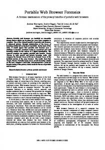
Figure 3: Special effects with image-based rendering and layering. Here motion blur is achieved by averaging several rendering passes.
ground and 2D- and 3D-annotations. Even more complex layering techniques with certain compositing methods, including mechanisms for general multi-pass techniques as proposed in [18] with the RenderedTexture node, are needed to implement image-based rendering techniques like for instance dynamic HDR glow or motionblur (see Fig. 3). For such advanced rendering effects which are - depending of the type of application - quite essential for evoking the sensation of presence and immersion, the possibility to render window-sized and view-aligned quads and additionally some way to control the composition method is needed. Besides this especially in immersive environments real time shadows are needed for depth cues and correct perception. For desktop applications and simple mono projector systems image-based rendering can be achieved by using an extended LayoutLayer node from the Rev1 specification, and additionally introducing novel X3DAppearanceChildNode types for advanced render state control for image compositing. This approach can be extended for stereo systems by introducing special shader uniform variables denoting such information like left/right eye (named ’StereoLeftEye’ in the following pixel shader code fragment) or even a cluster window id. This way creating stereo textures can be easily accomplished. Another challenge is how to treat these different kinds of layers in really immersive environments like e.g. the CAVE. Here, the correct positioning of user interface elements can be consistently handled with our special Viewspace node, which transforms its children to the coordinate system of the current active viewpoint. But there still exists no continuous conceptual model for handling pure effects layer nodes for mono/stereo and all display types ranging from a desktop PC to a tiled display cluster system. if (StereoLeftEye == 1) col = texture2D(left, gl_TexCoord[0].st); else col = texture2D(right, gl_TexCoord[0].st); Another important issue are multi resolution surfaces (e.g. LOD or adaptively tessellated NURBS) on the one hand and simulation systems (like physics and particle systems) on the other hand on multi screen setups. The latter can especially lead to problems when the simulation is non-deterministic and distributed across a cluster for all render windows. If the simulation calculations are not bound to the application thread but run on different client PCs, the result
is not necessarily the same and might therefore lead to rendering errors. Similar problems can occur with multi resolution meshes. If the view dependent tessellation is different on neighboring windows of tiled display systems this can also lead to artifacts. 4 I NTEROPERABILITY Any modern VR environment has to provide network-interfaces to incorporate application data at runtime, e.g. from simulator packages or external devices. Building different applications and services we observed that we should separate the interfaces in two groups. Application-Services are external interfaces which provide some access to the scene-graph elements, and System-Services are internal interfaces to distribute tasks (See Figure 4). We already presented some cluster and multi-threading aspect of interfaces [3] but would like to generalize these results.
with the VR system. The major drawback of this approach is that it just allows one-way communication due to the nature of the HTTP protocol: external software components are able to trigger actions, but the VR system itself cannot contact external software components. But for many applications this kind of communication is completely sufficient. An example for a DHTML based script is given in figure 5. str str str str str str str
= "/setFieldValue?node=shader"; += "&field=diffuseColor&value="; += diffR; += "+"; += diffG; += "+"; += diffB;
window.location = str; Figure 5: Web-page embedded JavaScript code example for setting a shader parameter via HTTP.
SOAP Interface. The SOAP [15] interface transforms the VRRuntime environment into a web-service. There are SOAP implementations for almost every language and environment available. The Microsoft .NET Framework and Java have native support built-in. The SAI on SOAP allows to do remote procedure calls into the VR-Framework but since HTTP is used as transport layer it cannot handle observers directly like the native interface.
Figure 4: Internal/ External Service Types.
4.1 Application Services Application services allow external components to access scenegraph elements like nodes. These interfaces should be application independent, support different access and manipulation functions but also some kind of data-observation methods. The X3D standard includes the Scene Authoring Interface (SAI), which defines the abstract scene access interface that can be used to interact with X3D worlds both from within the worlds or from external programs. The standard includes also two concrete implementations for this interface – one for ECMAScript and one for Java. These interfaces can be used from within the VR-Environment to define the behavior of Script-nodes, but also from within the web-browser to manipulate the scene-data from other web-page components. Since the VRruntime-environment is usually not running as web-browser plugin, we have to provide a network transparent interface. For this purpose, we present three SAI network-interfaces for different application classes. AEI. The Avalon-External-Interface implements the external SAIinterface while providing a asynchronous and fast binary network-transport layer. C++ and Java classes allow external applications to manipulate the scene-content and to register observers on scene-changes. This interface gives the best performance and feature set but uses a proprietary transport layer. HTTP Interface. The HTTP-SAI Version is based on a simple HTTP-GET encoding – therefore any language or tool that allows to download data from URLs is able to communicate
4.2 System Services The System Services are streaming protocols which are used to cluster parts of the media used for the user experience. In contrast to the SAI interfaces, this layer does not have any knowledge about nodes or the scene-graph. The Audio and Device Service are many useful to access hardware-units on remote machines. The clustering of graphics is essential for multi-screen support but also gives the system the ability to balance the load between different GPUs. Devices. The Human-Interface-Device HID layer is a network transparent transport layer to find and distribute data streams on different systems. This can include simple 3D or 6D streams but also more demanding image streams for AR applications. Graphics. The clustering uses an open-source implementation provided by OpenSG [6]. This layer provides the ability to use different sort-first/ sort-last algorithms to optimize the rendering performance. Audio. The SpatialSoundSystem (S3) service can be useful if the application server has no 3d-sound capacity or the speakers are actually plugged to another computer. There are some protocols for distributing 2D stereo streams but no public specification for spacial sound. All these services use the same Zero-Conf [13] based retrieval mechanism, and a simple HTTP white-board allows to monitor and reconfigure different aspects of every interface. 5 A PPLICATIONS AND R ESULTS In this section we present two applications running on our framework. The first one is using X3D interaction techniques in combination with the low-level and high-level sensors described above, the second one is also utilizing the presented web-interface.
5.1 VR-platform for heavy machine construction The aim of this project was to design a platform for the immersive modeling of heavy machines. Via a tracking system the position and orientation of a stylus are captured and integrated into the scene with low-level sensors. The immersive 3DUI is realized using highlevel sensors (e.g. X3D PointingDeviceSensors). The manipulation of virtual objects is combined with a “Snap-In” mechanism that supports the interactive assembling of several items which are part of a virtual tool box. Articulated links of correspondent objects are joined together and snapped in by “virtual magnetism” (Figure 6).
Figure 7: VR application for integrating virtual annotations into an immersive environment, deployed on a CAVE.
Figure 6: Immersive assembly Application.
5.2 Immersive Annotations Figure 7 and 8 show an application that allows the user to create virtual annotations and insert them into the scene. To provide an intuitive user interface, we use a PDA as all-purpose input device. The position and orientation of the PDA stick are captured by a tracking system. Thus, 2D-interactions (e.g. drawing of sketches, creating of annotations) can be performed on the PDA and 3D-interactions (e.g. navigating in the scene, manipulating of virtual objects) are provided by the Avalon system. The data exchange between PDA and Avalon is realized via HTTP-SAI. The application can be deployed on different HW setups like CAVE (Figure 7) or PowerWall (Figure 8). R EFERENCES [1] Althoff, Stocker, and McGlaun. A Generic Approach for Interfacing VRML Browsers to Various Input Devices and Creating Customizable 3D Applications. Web3D, 2002. [2] J. Behr. Avalon, 2007. http://www.ini-graphics.net/ avalon. [3] J. Behr, P. D¨ahne, and M. Roth. Utilizing x3d for immersive environments. In Web3D ’04: Proc. of the ninth int. conf. on 3D Web technology, pages 71–78, NY, USA, 2004. ACM Press. [4] P. Figueroa, O. Medina, R. Jimenez, J. Martinez, and C. Albarracin. Extensions for interactivity and retargeting in x3d. In Web3D ’05: Proceedings of the tenth international conference on 3D Web technology, pages 103–110, New York, NY, USA, 2005. ACM Press. [5] OpenSceneGraph. Open scene graph documentation. http://www.openscenegraph.org, 2003. [6] OpenSG. Opensg, 2006. http://www.opensg.org. [7] N. F. Polys and A. Ray. Supporting mixed reality interfaces through x3d specification. In Workshop at the IEEE Virtual Reality, 2006. [8] X. Project. Xj3d extensions - input/output extensions, 2006. http://www.xj3d.org/extensions/device.html.
Figure 8: Inserting virtual annotations into a VR environment, deployed on a PowerWall.
[9] D. Reiners, G. Voss, and J. Behr. A Multi-thread Safe Foundation for Scene Graphs and its Extension to Clusters. Eurographics Workshop on Parallel Graphics and Visualisation 2002. Proceedings, 2002. [10] J. Rohlf and J. Helman. IRIS Performer: A high performance toolkid for real-time 3D graphics. ACM Computer Graphics, SIGGRAPH 94, 1994. [11] R. Stiles, S. Tewari, and M. Metha. Adapting VRML 2.0 for Immersive Use. VRML 97, Second Symposium on the Virtual Reality Modeling language, 1997. [12] P. Strauss and R. Carey. An object-oriented 3D graphics toolkit. ACM Computer Graphics, 1992. [13] The Internet Engineering Task Force. The ZeroConf Network Protocoll Spezification. www.zeroconf.org, 2004. [14] H. Tramberend. Avocado – a distributed virtual environment framework. http://www.ercim.org/publication/Ercim News/enw38/tramberen d.htm, 1999. [15] W3C. Xml Protocol Working Group, sOAP Version 1.2 Specification. http://www.w3.org/2000/xp/Group/, 2000. [16] Web3DConsortium. Extensible 3D (X3D) ISO/IEC CD 197751r1:200x, 2006. http://www.web3d.org/x3d/specifications/ISO-IEC19775-X3DAbstractSpecification Revision1 to Part1/. [17] WorldToolKit. Sense8 Corporation; WorldToolKit: Virtual Reality Support Software. 4000 Bridgeway Suite 101, Sausalito, CA 94965, telephone : (415) 331-6318., 1994. [18] Xj3D. Xj3d dynamic texture rendering ext., 2004. http://www.xj3d.org/extensions/render texture.html.