The receiver calculates the code based on the incoming bits and compares it with ... always detect (dmin â 1) errors, but can only correct half of ... information bits are needed. i.e, We ... provide redundant bits in the generated code, though the.
International Journal of Soft Computing and Engineering (IJSCE) ISSN: 2231-2307, Volume-4, Issue-2, May 2014
A Lab VIEW Based Extended (10, 5) Binary Hamming Code Generator for Telecommanding Applications Sreelatha P, P Pradeep Kumar, S V Mohankumar Abstract- The paper presents the design details of an extended binary Hamming code generator for generation of codewords suitable for remote applications needing telecommands. It is required that these telecommand codes maintain a minimum Hamming distance of three. For the present application, a suitable (10, 5) Extended Hamming code generator is designed for 5 data bits, which generates a corresponding 10 bit codeword for each data word. The design implemented in LabVIEW is detailed here along with a distance table showing the Hamming distance between the generated codes.
His search for error-correcting codes led to the Hamming Codes, which are popular as perfect 1-error correcting codes and the extended Hamming Codes, 1-error correcting and 2-error detecting codes [1], [2], [3], [4], [5]. That is, any received word with at most one error will be decoded correctly and the code has the smallest possible size of any code that does this. Thus Hamming codes can be categorized as SEC-DED (Single Error Correcting - Double Error Detecting) codes. Hamming codes are code words formed by adding redundant check bits, or parity bits, to a data word. These are one of the most effective codes for error recovery and are used in situations where random errors are likely to occur. Hence, for telecommanding applications also, the codewords generated as extended hamming codes are considered appropriate.
Keywords - Extended Hamming code, Hamming distance, error correction, SEC-DED, LabVIEW.
I. INTRODUCTION In digital transmission systems, an error occurs when a bit gets altered between transmission and reception; that is, a binary 1 is transmitted and a binary 0 is received, or a binary 0 is transmitted and a binary 1 is received. Two general types of errors can occur in these cases: single-bit errors and burst errors [1], [2]. A single-bit error is an isolated error condition that alters one bit but does not affect nearby bits. A single-bit error can occur in the presence of white noise, when a slight random deterioration of the signal-to-noise ratio is sufficient to confuse the receiver's decision of a single bit. A burst error of length B is a contiguous sequence of B bits in which the first and last bits and any number of intermediate bits are received in error. Burst errors are more common and more difficult to deal with. Burst errors can be caused by impulse noise or by fading. These errors necessitate the use of error detection codes also to be transmitted as a function of the bits being transmitted. Thus this code is appended to the data bits and is transmitted. The receiver calculates the code based on the incoming bits and compares it with the incoming code to check for errors. A detected error occurs if and only if there is a mismatch. Remote control applications demand that error correction also be implemented to the possible level, so that the receiver itself takes care of error correction. [4], [5]. In such cases, each m-bit block of data is mapped onto an n-bit block (n>m) called a codeword which has (n-m) check bits in addition to the data bits. This codeword is verified at the receiver end to check and correct for certain errors. In the late 1940’s Richard Hamming recognized that the further evolution of computers required greater reliability, in particular the ability to not only detect errors, but correct them.
II. TYPES OF HAMMING CODES In practice, there are three types of Hamming codesstandard, extended and q-ary [3]. The standard Hamming code is normally designed to have a minimum Hamming distance of 3 between any two codewords. Eg., Hamming (7,4) is a standard type of Hamming code that encodes 4 bits of data into 7 bits by adding 3 parity bits. Extended Hamming (EH) code is designed to have the minimum distance between any two codewords as one more than the standard case, so an extended Hamming Code is a 1-error correcting and 2-error detecting code. The general construction of an extended code and a binary Hamming code is the same. The extra bit for the extended code is added as the parity check bit. For the above example, the extended Hamming code is denoted as Hamming (8, 4). In q-ary Hamming codes[5], the binary construction generalizes to Hamming codes over an alphabet A={0, …, q}, q ≥ 2. For a given r, an r × (qr-1)/(q-1) matrix M is formed over A, any two columns of which are linearly independent. Thus M determines a n-row, k-column matrix of the form [(qr-1)/(q-1), (qr-1)/(q-1) – r] = [n,k] q-ary Hamming Code for which M is the check matrix. III. WHAT IS HAMMING DISTANCE? The Hamming distance between two code words is the number of bits in which two code words differ [1], [2]. The minimum Hamming distance for a code is the smallest Hamming distance between all pairs of words in the code and determines its error detecting and correcting capability. This distance is provided by adding a suitable number of parity bits to a data word. To guarantee the detection of up to s errors in all cases, the minimum Hamming distance in a block code must be dmin = s + 1. To guarantee correction of up to t errors in all cases, the minimum Hamming distance in
Manuscript received on May, 2014. Sreelatha P, Space Physics Laboratory, Vikram Sarabhai Space Centre, Trivandrum, India. P Pradeepkumar, Space Physics Laboratory, Vikram Sarabhai Space Centre, Trivandrum, India. S V Mohankumar, Space Physics Laboratory, Vikram Sarabhai Space Centre, Trivandrum, India.
70
Published By: Blue Eyes Intelligence Engineering & Sciences Publication Pvt. Ltd.
A Lab VIEW Based Extended (10, 5) Binary Hamming Code Generator for Telecommanding Applications
a block code must be dmin = 2t + 1. Hamming codes can always detect (dmin – 1) errors, but can only correct half of those errors. It is also seen that when more parity bits are added, more errors can be detected and corrected. In telecommanding applications where remote control of a system is done by means of codewords, it is imperative that the codewords maintain a Hamming distance of at least three, so that each codeword is interpreted properly by the remote system. Depending on the number of data bits available for telecommands and the number of commands needed for operating the system remotely, the number of codewords is chosen. This forms the criteria for finalizing the number of bits needed to generate the Hamming code.
the parity bit determines the sequence of bits that it alternately checks and skips. Thus for a (9,5) binary Hamming code generator, the bits x3, x5, x6, x7 and x9 are chosen according to the data message and x1, x2, x4 and x8 form the check bits. For telecommanding application, the extended Hamming code is preferred and it becomes Hamming (10, 5). This is designed by adding a parity bit x0[3]. This bit is the sum of all the individual bits in the code word and will be ‘1’ for odd number of ones in the word and ‘0’ for even number of ones in the codeword. The check bits are calculated according to Hamming code definitions, like x1 is the sum of all odd numbered bits. As the check bits are of parity type, the sum here is symbolic and indicates whether the numbers of ones are odd or even. The design flow of the program is represented in the flowchart depicted in figure 1 below. As explained above, the same logic can be used for generating 4 parity bits for the data bits ranging from 5 to 11. The software is designed to cater to m value from 5 to 11 data bits. The parity bits have been individually calculated according to the following equations for the default case of 5 data bits
IV. DESIGN OF HAMMING CODE GENERATORS Suppose we have a set of n-bit code words consisting of m data bits and r parity bits. An error could occur in any of the n bits, so each code word can be associated with n erroneous words at a Hamming distance of 1. Therefore, we have n + 1 bit patterns for each code word: one valid code word, and n erroneous words. With n-bit code words, we have 2n possible code words consisting of 2m data bits (where n = m + r). This gives us the inequality: (n + 1) × 2 m≤ 2 n Because n = m + r, the above relation becomes (m + r + 1) × 2 m ≤ 2 m + r or (m + r + 1) ≤ 2 r This inequality gives us a lower limit on the number of check bits that we need in our code words. For the present telecommanding application, a maximum of 32 telecommands are allowed. This implies that 5 information bits are needed. i.e, We have data words of length m = 5. Then (5 + r + 1) ≤ 2r implies that r must be greater than or equal to 4. i.e., to build a code with 5-bit data words that will correct single-bit errors, we must add 4 check bits, creating code words of length 9. The above equation can also be used to find out the length of data word for which the number of check bits is fixed. Referring to the above example of 4 parity bits, we can see that (m + 4 + 1) ≤ 24 provide a range of values for m. In order to satisfy this equation, m can have a value from 1 to 11. For m values from 1 to 4, it is understood that 4 parity bits provide redundant bits in the generated code, though the number of errors that can be corrected is maintained as 1. Hence, for all practical purposes, the m value chosen is between 5 and 11 for 4 parity bits. The design algorithm states that each bit position corresponding to an even power of 2 will be occupied by a check bit and the rest are the data bits to be encoded. These check bits contain the parity of each bit position which is used in its generation. i.e, Each parity bit calculates the parity for some of the bits in the code word. The position of
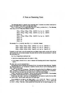
P1 = d1 + d2+ d4+ d5 P2 = d1 + d3 + d4 P3 = d2 + d3 + d4 P4 = d5 P0 = Sum of all bits = (P1 + .. + P4) + (d1 + ….+ d11) The final code word for the 5 bit case is arranged in the format P1 P2 d1 P3 d2 d3 d4 P4 d5 for H code and P0 P1 P2 d1 P3 d2 d3 d4 P4 d5 for EH code. The above equations represent the special case of m =5. The general form of equations which include the cases for m = 6 to 11 can be given as P1 = d1 + d2 + d4 + d5 + d7 + d9 + d11 P2 = d1 + d3 + d4 + d6 + d7 + d10 + d11 P3 = d2 + d3 + d4 + d8 + d9 + d10 + d11 P4 = d5 + d6 + d7 + d8 + d9 + d10 + d11 P0 = (P1 + .. + P4) + (d1 + …. + d11) The final codeword for the maximum of 11 data bits will have the format as given below P1 P2 d1 P3 d2 d3 d4 P4 d5 d6 d7 d8 d9 d10 d11 for H code and P0 P1 P2 d1 P3 d2 d3 d4 P4 d5 d6 d7 d8 d9 d10 d11 for EH code The software is designed to cater to the case of upto 11 bits according to the design flow chart depicted in figure 1.
71
Published By: Blue Eyes Intelligence Engineering & Sciences Publication Pvt. Ltd.
International Journal of Soft Computing and Engineering (IJSCE) ISSN: 2231-2307, Volume-4, Issue-2, May 2014
Figure 1 Design flow chart for Extended Hamming code generation This design is implemented in LabVIEW 2010 which is a popular graphical programming language. LabVIEW programs are called Virtual Instruments (VIs) as their appearance and operation imitate physical instruments [6]. The LabVIEW programs consist of a user interface called front panel and the area where code resides is the block diagram. A comprehensive set of tools is available for data or signal acquisition, analysis, display as well as storage. As explained above, in the present telecommand application, an
extended Hamming (10, 5) code is to be generated through the software. The software developed is made more generic and has the advantage that the same program can be used to generate codewords for applications that require the minimum Hamming distance of 4, which according to the inequality stated above is upto 11 data bits. The front panel of the software is shown in figure 2.
Figure 2 Front panel of Extended Hamming Code generator
72
Published By: Blue Eyes Intelligence Engineering & Sciences Publication Pvt. Ltd.
A Lab VIEW Based Extended (10, 5) Binary Hamming Code Generator for Telecommanding Applications
cases, except for the codeword comparison with itself. This ensures that one bit error can be easily corrected as illustrated in the example below. Suppose the transmitted codeword is 1100000011 and with a single bit error this is received as 1000000011. On observing all the codewords it is seen that no codeword matches the received codeword, and so assuming a 1-bit error for each bit position, ten codewords that can be reconstructed are 0000000011, 1100000011, 1010000011, 1001000011, 1000100011, 1000010011, 1000001011, 1000000111, 1000000001, 1000000010. Out of these codewords, it can be seen that the second one i.e, 1100000011, only matches with the generated codewords, identifying that this is the transmitted codeword.
V. GENERATION OF TEST MATRIX The fixed-length codewords generated from the above program are saved onto a text file. Before assigning these codes for the telecommanding application, it is to be ensured that the individual codewords maintain the minimum Hamming distance of 4. For this, another program is also developed in Matlab to verify that the individual codewords satisfy the minimum Hamming distance between them. This software counts the number of bit changes between each individual codeword and writes the difference in a matrix form. This generated output saved in matrix format is shown below as figure 3. Here, the codewords are numbered 1 to 32 and the exact codeword is shown as the second column. The distance between each codeword and the other codewords is shown alongside on the right columns. It can be seen that the distance between any two codewords is at least 4 in all the
Figure 3 Hamming distance test matrix of (10, 5) Hamming code [4]
VI. CONCLUSION The Hamming code concepts described above can find application in any digital communication system that requires error checking and single bit error correction. In all the cases, the errors are assumed to be of non-systematic and random nature. For remote control of a digital system through telecommands, the number of information bits is chosen first and then the check bits are generated according to Hamming code generator design. This guarantees that no two codes overlap and a single bit error will not make the system to read any particular command differently. The software developed in LabVIEW satisfies these conditions and the generated EH codes are verified for a specific case of 5 information bits.
[5]
[6]
Sreelatha P is a Senior Engineer at Space Physics Laboratory, Vikram Sarabhai Space Center, Trivandrum. She finished her B.Tech in Electronics and Communication Engineering (1991) and M.Tech in Microwave & Television Engineering (1994) from College of Engineering, Trivandrum. She has submitted her Doctoral thesis to the University of Kerala in 2013. She has experience in design and development of various RF and data acquisition systems for the scientific projects handled by the laboratory. She has also experience in checkout and software design for various scientific payloads of SPL and is the Checkout Project Manager for some prestigious payloads of the laboratory.
REFERENCES [1] [2] [3]
Bhattacharya D. K. and S Nandi, “Theory and design of SEC-DED-AUED codes”, IEE Proceedings on Computers and digital techniques, Vol. 145, Issue 2, pp 121-126, 1998. Bhattacharya D. K. and S Nandi , “An Efficient Class of SEC-DED-AUED Codes”, Proceedings of the Third International Symposium I-SPAN97, pp 410-416, 1997. www.ni.com
Proakis J.G., Digital Communications, 4th Edition, McGraw Hill Co., 2001. Forouzan, Behrouz A., Data Communications and Networking, 4th Edition, McGraw Hill Higher Education, 2007. Hall J.I., “Notes on Coding Theory”, http://www.mth.msu.edu/~jhall/classes/codenotes/coding-notes.html
73
Published By: Blue Eyes Intelligence Engineering & Sciences Publication Pvt. Ltd.