Nov 28, 2013 - A second attempt to build an ion ... the application of an iridium covered W(111) SAT ... the electron interference pattern in this interferometer,.
Biprism Electron Interferometry with a Single Atom Tip Source G. Sch¨ utz1 , A. Rembold1 , A. Pooch1 , S. Meier1 , P. Schneeweiss2 , A. Rauschenbeutel2 , A. G¨ unther3 , W.T. Chang4 , I.S. Hwang4 and A. Stibor1 Institute of Physics and Center for Collective Quantum Phenomena in LISA+ , University of T¨ ubingen, Auf der Morgenstelle 15, 72076 T¨ ubingen, Germany 2 Vienna Center for Quantum Science and Technology, TU Wien - Atominstitut, 1020 Vienna, Austria 3 Institute of Physics and Center for Collective Quantum Phenomena in LISA+ , University of T¨ ubingen, Auf der Morgenstelle 14, 72076 T¨ ubingen, Germany 4 Institute of Physics, Academia Sinica, Nankang, Taipei, Taiwan, Republic of China
arXiv:1311.7323v1 [physics.optics] 28 Nov 2013
1
Experiments with electron or ion matter waves require a coherent, monochromatic and long-term stable source with high brightness. These requirements are best fulfilled by single atom tip (SAT) field emitters. The performance of an iridium covered W(111) SAT is demonstrated and analyzed for electrons in a biprism interferometer. Furthermore we characterize the emission of the SAT in a separate field electron and field ion microscope and compare it with other emitter types. A new method is presented to fabricate the electrostatic charged biprism wire that separates and combines the matter wave. In contrast to other biprism interferometers the source and the biprism size are well defined within a few nanometers. The setup has direct applications in ion interferometry and Aharonov-Bohm physics. PACS numbers: 03.75.Dg; 03.75.-b; 41.85.-p; 07.77.Ka; 07.78.+s
I.
INTRODUCTION
In consideration of the success with interferometers for neutral atoms [1–4] and molecules [5–7], efforts were made to expand the field towards matter wave experiments with ions. They started with the realization of the first biprism interferometer for helium ions by Hasselbach et al. [8–11]. The additional parameter charge combined with the internal structure of ions offer significant advantages in comparison to interferometers for electrons and neutral atoms. Ion interferometers could open up the door for a class of novel quantum optical experiments to test the influence of inner structure in the magnetic Aharonov-Bohm effect [12–14] or the first direct measurement of the electric Aharonov-Bohm effect [14]. Furthermore such a device may allow for interferometry experiments with laser excitation of inner ionic states [13], decoherence studies [15] and might enable for extremely sensitive sensors for rotations and accelerations [16]. However, in the first and only realization of an ion interferometer [8–11], the low helium ion brightness of the field ion source turned out to be the weak point of the design. Very long exposure times of 15 min had to be taken into account to accumulate interference fringes and diffraction for 3 keV He+ ions. For that reason further quantum optical experiments have not been possible. A second attempt to build an ion interferometer was made by Krenn et al. [17]. Also in this device the low count rate of the ion source was the main challenge and prevented the successful generation of ion interferences. To solve this issue an alternative source needs to be applied. It was shown in [18–22] that single atom tip (SAT) field emitters generate coherent beams with high brightness for electrons and ions.
In this article we demonstrate for the first time the application of an iridium covered W(111) SAT source in a biprism interferometer. The device is based on the setup of Hasselbach et al. [8–11]. We analyze the electron interference pattern in this interferometer, characterize the performance of the SAT emitter in a field ion and field electron microscope and compare it with other emitter types. Furthermore, a new method to fabricate a coherent biprism beam splitter is presented. In conventional biprism electron or ion interferometers [8–11, 15, 23–25] the source size and the biprism diameter are not known with high accuracy. In our setup these parameters are well defined within several nanometers. Recently an electron beam from a SAT source was diffracted and interfered on a carbon nanotube [21, 22]. Although the high coherent properties of this source could be demonstrated, it is likely that this scheme cannot be applied for ion interferometry, since the fringe pattern magnification was performed geometrically with a distance of several hundred nanometers between the tip and the nanotube. For ions the tip voltage needs to be higher and the distance to the nanotube shorter, which may cause arcing. In this context our setup has the advantage that the interference pattern is magnified by a quadrupole lens. Furthermore the interference can be tuned by an adjustable potential on the biprism fiber, which is not possible in the nanotube approach.
II.
BIPRISM INTERFEROMETRY
In biprism interferometry [23] an ideally point-like electron or ion source illuminates coherently a biprism fiber. Applying a positive (for electrons) or negative (for ions) potential on the wire leads to a separation and deflection of the matter wave. The beam paths combine again
2 shortly after the biprism and interfere with each other. As a result an interference pattern parallel to the biprism wire can be detected in the plane of observation.
A.
Single Atom Tip Field Emitters
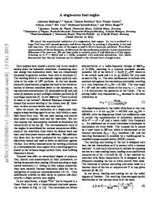
The choice of the beam source with a highly coherent signal is crucial for an electron or ion biprism interferometer that should be capable of performing sophisticated future matter wave experiments. The lateral and longitudinal coherence length, the emission angle, the signal intensity and the spatial stability depend on the source. An established technique to produce a coherent electron beam is to etch a metal tip and set it on a high negative potential in vacuum until field emission starts. To generate an ion beam, a positive voltage is applied to ionize and accelerate gas atoms at the tip end due to the high electric field. Several different tip types have been developed in the last decades. The electron emission characteristics of four of them are listed in Tab. I. In the first one, electrons are thermally emitted by a comparably blunt tungsten or lanthanum hexaboride (LaB6 ) tip and accelerated towards a counter electrode [26]. The second type describes an etched tip where the electrons are extracted by field emission. The third one, the so called ”supertip”, is an etched tip, where a tiny protrusion is created [27, 28]. This was the source in the first ion interferometer [8–11]. Due to its geometry, the emitted electron or ion matter wave experience a self focusing effect. An ion beam is emitted with a high angular confinement of about 2◦ , instead of about 60◦ full emission angle for etched tips [29] without the protrusion. However, it was mentioned in [10] for ion emission that this protrusion, being the emission center, is spatially only stable for about one hour, with a large uncertainty between different supertips. This is a disadvantage for the use in ion interferometry since the beam alignment before signal acquisition is typically longer than this time and the instability leads to uncorrelated phase shifts, destroying the contrast. Also the maximal beam brightness of 1014 A/m2 sr for ionization gas with a partial pressure of 1 mbar (Tab. I, [30]) could not be reproduced in the ion interferometer of Hasselbach et al. [10]. There the maximal helium beam brightness was in the range of 1012 A/m2 sr. This tip type is therefore not practical for further experiments with a larger beam separation and a long signal integration time, such as required for Aharonov-Bohm physics [12]. The fourth emitter type in Tab. I is the SAT which was first realized by Fu et al. [20] and improved by Kuo et al. [18, 19]. A sketch of this tip is shown in Fig. 1. It consists of an etched single crystal (111) tungsten wire where a monolayer of iridium is deposited [18]. After installation into ultrahigh vacuum, it is resistively heated several times to a temperature between ∼ 1000 and 1300 K for 3 minutes. Due to surface energy optimization, the tip forms a three-sided atom pyramid with
FIG. 1: (Color online) Sketch of field electron or field ion emission from a SAT as a coherent source for interferometry. The arrows indicate the direction of the electric field lines orthogonal to the tip surface resulting in a self focusing effect.
a single iridium atom at the apex. As determined in [19], the nano-pyramid can be regenerated in vacuum over 50 times by annealing and the long time stability of these SAT sources is extraordinary high. Variations in the ion current of 3 % for helium and 5 % for hydrogen for about 30 minutes have been measured and they do not show any degradation after a total operation time of 80 hours [19]. As for the supertips, a self focusing effect limits the emission angle leading to a high beam brightness for helium ions of 2 × 10¹⁵ A/m2 sr for ionization gas with a partial pressure of 1 mbar [19]. The opening angle α of a coherent emission can be assessed by the relation for the angular coherence constraint d · α � λdB 2 [23, 31] where d is the source size and λdB the de Broglie wavelength of the particle. A SAT field emitter yields the smallest source size possible. The emitting area is only a single atom, with a diameter of ∼ 0.3 nm in case of an iridium covered SAT [19]. This results in a large α and in a broad coherently illuminated area on the biprism and the detector. It is therefore well suited for electron as well as for ion interferometry with short de Broglie wavelengths.
FIG. 2: (Color online) Sketch of the field electron or field ion microscope to characterize the SAT (not to scale). The electrons or ions emitted from a SAT source can be spatially resolved in a MCP detector in combination with a fluorescent screen and a CCD camera. For the counting of high signal rates the detector can be moved upwards to position a Faraday cup into the beam path.
3 Thermal emission Etched tip Source diameter Energy spread [eV] Max. brightness
Supertip
SAT