BLIND SINGLE-USER ARRAY RECEIVER FOR MAI CANCELLATION IN MULTIPATH FADING DS-CDMA CHANNELS Li-Ke Huang and Athanassios Manikas Department of Electrical and Electronic Engineering Imperial College of Science, Technology and Medicine London SW7 2BT United Kingdom Tel: +44 (0)20 7594 6266 Fax: +44 (0)20 7594 6234 e-mail:
[email protected]
ABSTRACT In this paper, a blind subspace-type single-user array directsequence code division multiple access (DS-CDMA) receiver is proposed based on a new joint space-time channel estimation technique for frequency-selective channels. In the proposed approach, the spatio-temporal multipath channel parameters associated with the desired user are jointly estimated with the number of identifiable paths not limited by the number of antennas. Then these estimated parameters are employed to efficiently combine the desired multipath rays while, at the same time, (asymptotically) complete MAI cancellation is achieved.
1 INTRODUCTION With DS-CDMA chosen as the air-interface for the next generation of wireless communication systems/networks, the intention is to support as many users as possible operating at very high data rates in the presence of severe channel distortion effects. In these systems the multiple users transmit asynchronously, overlapping in both time and frequency and, therefore, resulting in multiple-access interference (MAI) which, eventually, limits the system performance [1,2]. Furthermore, the presence of multipath propagation effects not only increases the MAI by introducing extra interfering paths, but also distorts the desired signal component (frequency-selective fading). However, a well designed DS-CDMA system may exploit:
• the multipath channel by recombining the multipath rays in a positive way, thereby combating the multipath fading effects;
• the highly structured signal format of the MAI to provide MAI cancellation; thus significantly improving the overall system’s performance. However, for this exploitation to be effective, channel parameters (such as multipath delays, path coefficients, etc.) must be estimated prior to the subsequent data symbol detection. One of the main concerns of this paper is channel estimation using an array of antennas. The use of an antenna-array makes it possible to mitigate the above channel effects and provides the potential benefit of exploiting the spatial structure of the channel leading to joint spatio-temporal reception space-time communications. It has been argued that joint spatio-temporal reception/processing is a breakthrough approach for future generation of wireless communications [3,4,5] and the estimation of the spatio-temporal channel parameters is central to the research work presented in this paper.
2 SIGNAL MODELLING In an Q -user asynchronous DS-CDMA system, the 3>2 user’s baseband transmitted signal may be written as _
73 a>b æ " a3 c8d -T R Ä3 a> 8X-= b, 8X-= é > a8 þ "bX-= (1) 8æ_
where ea3 ·8¸Ä a8 a f is the 3>2 user’s data symbol sequence of ö"s, X-= is the data symbol period, and -T R Ä3 a>b is one period of the pseudo random spreading waveform associated with the 3>2 user, which is modelled as follows: ac " -T R Ä3 a>b æ " !3 c5 d -1 a> 5X- b, 5X- é > a5 þ "bX- (2) 5æ!
In Equation (2) e!3 c5 d ö"f represents the 3>2 user’s PNsequence of period a- æ X-= ³X- and -1 a>b denotes the chip pulse shaping waveform of duration X- . Let us assume that the base station has an array of R antennas and that the transmitted signal of the 3>2 user arrives at the base station via O3 paths, a3 æ "Ä ÃÃÃÄ Q . Consider the 4>2 path of the 3>2 user arrives at the array from direction )34 with channel propagation parameters "34 and 734 representing the complex path
?
gain and path delay, respectively. Let W34 æ W a)34 b denote the array manifold vector (array response) associated with the 4>2 path of the 3>2 user, which has the form: Wa)34 b æ expí 4 æ r X k34 û where æ r æ cb is a complex white Gaussian noise vector with covariance matrix 5# íR and
ò3 "3
ab
73 >
æ æ æ
·W31 , W3# , Æ , W3O ¸ ·"3" , "32 , Æ , "3O ¸X ·73 > 73" , 73 > 732 , Æ ,73 > 73O ¸X 3
a b a b 3
a
3
b
VR óO VO ó" V O ó" 3
3
3
By discretising the signal-vector Ba>b (using chip matched filters followed by chip rate samplers) and then passing the samples
¿
through a tapped-delay line of length equal to #a- , as shown in Figure-", the data matrix ðc8d VR ó2a- is formed, ðc8d æ cB" c8d, B# c8d, ÃÃÃ , B5 c8d, ÃÃÃ , BR c8ddX
i.e.
(4)
representing the contents of all R tapped-delay lines associated with the 8>2 data symbol period. Note that due to the asynchronous operation of the system, the tapped-delay lines contains contributions from the previous and next symbols as well as the current symbol. To further model the received signal we need to define the reference temporal manifold vector æ3 of the 3>2 user and a shift operator matrix û. The vector æ3 is defined below æ3 æ !3 c!d, !3 c"d, Æ , !3 ca- "d,
X ñ !a e#a- ó" c X
(5)
and represents one period of the PN-sequence of the 3>2 user extented with zeros to have a length of #a- . This corresponds to a zero path delay situation. On the other hand, û is a #a- ó #amatrix defined as follows ¹! »" » û æ »! » È º!
! ! " È !
Ç Ç Ç É Ç
! ! ! È "
!¼ !¾ !X ¾ ! ¾ æ ï #a- " ¾ í#a- " È ½ !
! !#a- " ð
(6)
a
õ
!
a
CMF
2nd path
û a- û634 æ3 a3 c8 þ "dü"34 þ 8c8d with å denoting the Kronecker product. In Equation (8), the
term W()34 ¶ å íû 6 æ3 û æ 34 V#ac R ó" is defined as the spatiotemporal manifold vector for the 4>2 path of the 3>2 user. Using this spatio-temporal manifold vector, Bc8d can be rewritten in a compact form as
"
î
¹ º
¼ ½
a3 ·8 "¸ a3 ·8¸ B·8¸ æ ·ø3Äprev "3 , ø3 "3 , ø3,next "3 ¸ þ 8·8¸ 3æ" a3 ·8 þ "¸ Q
(9)
where, for the 3>2 user, the matrix ø3 V#a R óO has as columns the spatio-temporal manifold vectors 34 , a4 æ "Ä ÃÃÃÄ O3 , while ø3Äprev and ø3,next can be expressed as a function of ø3 as follows: -
3
Tc
Tc
Tc
Tc
Tc
Tc
Tc
Tc
B#8ñ
Tc
Ki th path CMF
BR8ñ
Before we proceed let us define the (2R- ó 2R- ) Fourier Transform matrix ú ú æ 9! Ä 9" Ä 9# Ä ÇÄ 9a#a- "b ñ (11) where 9 æ c ",
9" ,
9# ,
Ç,
9µ#a- "¶ d
X
with 9 æ expí 4 ##a1 û. -
34
3æ" 4æ"
34
Tc
Tc CMF
(8)
34
B8ñ B"8ñ
Tc
3 BLIND SINGLE-USER CDMA ARRAY RECEIVER
æ ! ! W()34 ¶ å çaûX b û6 æ3 a3 c8 "d þ û 6 æ3 a3 c8d þ -
Bµ>
(7)
Based on Equation (7), we can formulate the spatio-temporal received signal-vector X
Ù
TDL length = 2Nc
Figure 1: The front-end of the proposed array receiver.
634 æ i734 ³X- j mod a- .
Bc8d æ B" c8dX Ä ÃÃÃ Ä B5 c8dX Ä ÃÃÃ Ä BR c8dX ñ
¼ ½
CMF = Chip Matched Filter, TDL = Tapped Delay Line
where 634 is the discrete version of the path delay 734 ,
Q O3
Ø
1st path
ith User
û a- û634 æ3 a3 c8 þ "dü"34 exp» 4 2 data symbol can be estimated as ." ·8¸
æ A1L B ·8¸
"
û øL æ ," ""L íøL " 8 ø" " 8 ø" "" a" ·8¸ þ 8" ·8¸
with ñD1; representing the covariance matrix of a .R element subvector D1; c8d of D" c8d (formed according to Figure-2) with . #a- . Note that U overlapping subvectors are needed in this procedure satisfying the following conditions #
æ ," l"" l# a" ·8¸ þ 8" ·8¸
(20)
where it can be easily proven that the power of the noise term # 8" ·8¸ æ AL 1 8·8¸ is equal to 5 .
aR
#
a-
-
#
a-
D"·8¸æ .
.
.
1
2
N
1
2
1
N
2
N
.R D""·8¸æ D"#·8¸æ D"U·8¸æ
.
.
.
1
2
N
1 st
1
2
N
2 nd
N
Q th
1
2
(17)
Q subvectors formed from D"·8¸
Figure 2: Forming the Q overlapping subvectors for temporal smoothing.
4
4æ) ""*° %X-
4æ* %!° #)X-
4 æ "! (!° #%X-
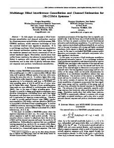
It is clear from Figure-3 that all paths of the desired user (User 1) are successfully identified/estimated. The second set of results is related to the decision variable ." ·8¸ of the proposed receiver when the receiver operates in the presence of finite averaging effects. This implies that there are estimation errors due to the finite observation interval which allow some interference components (terms MAI and ISI of Equation (10)) to pass to the decision variable. Two observation intervals of length equivalent to 100 bits and 1000 bits are considered. The desired user transmits these bits over a multipath channel with three resolvable multipaths in the presence of "! single path MAI-users with each user assigned a Gold sequence of length $". The power of the noise is assumed #!dB below, and the power of the MAI-users 20dB above, the desired signal power and a 5-element uniform linear array of antennas is used. The results are shown in Figure-4 demonstrating that the larger the observation interval the smaller the MAI components passing to the proposed receiver’s output. In addition, for the 1000 bits case, the RAKE receiver, as well as the ’decorrelating’ receiver, have been simulated for the same array environment and the results are shown in Figures 5a and 5b respectively. It is clear from these figures that the proposed receiver provides a significant improvement over the RAKE receiver. It is important to highlight that both the RAKE and proposed receiver use only the PN code of the desired user (single user). In contrast the ’decorrelating’ receiver uses the PN codes of the whole set of users (multi-user receiver) but, despite this, its performance is comparable to the single user receiver proposed in this paper. Other simulation results, not presented in this paper, also show that the proposed structure outperforms the decorrelating receiver in the case of imperfect channel estimates and demonstrate its robustness against unresolved multipath rays.
dB
6"4
Table-1: Desired user’s parameters 4æ$ 4æ% 4æ& 4æ' 4æ( '&° )!° *!° "!!° #!° ")X- "#X- #$X- &X"&X-
6
c d
µ
SEX E S 0H
Figure 3: 2D MUSIC spectrum for User 1. Proposed Receiver (Case 1)
1 Sergio Verdu, Multiuser Detection, Cambridge University Press, 1998. c2d Upamanyu Madhow, “Blind Adaptive Interference Suppression for Near-Far Resistant Acquisition and Demodulation of DirectSequence CDMA Signals”, IEEE Transactions on Signal Processing, Vol.45, NO.1, January 1997. c3d Babak Khalaj, Arogyaswami Paulraj and Thomas Kailath, “2D RAKE Receivers for CDMA Cellular Systems”, IEEE 1994. c d
0.4
0.5
0
-0.5
0.2 0 -0.2 -0.4 -0.6 -0.8
-1 -3
-2
-1
0 Real Part
1
2
-1 -4
3
-3
-2
-1
(a)
0 Real Part
1
2
3
4
(b)
Figure 4: Plotting the decision variable ." ·8¸ for two observation intervals equivalent to: a) "!! bits and b) 1000 bits. 2D RAKE Receiver
ST Multiuser Decorrelating Receiver
4
1
3 2 Imaginary Part
REFERENCES
0.8 0.6
5 CONCLUSIONS This paper presents a blind single-user space-time receiver for frequency-selective DS-CDMA channels, based on an innovative joint space-time multipath channel estimation procedure. The proposed receiver has a subspace-type structure, and is able to identify jointly the coherent multipath delays and DOA in the presence of MAI’s.
Proposed Receiver (Case 2)
1
Imaginary Part
)"4
4æ# #!° "!X-
5
c d
Imaginary Part
In this section, some illustrative simulation results are presented in order to demonstrate the main features of the proposed receiver. The first set of results is related to the joint direction and time of arrival (DOA,TOA) estimation part of the proposed receiver and is shown in Figure-3. The scenario used is a uniform linear array of five antennas operating in the presence of three cochannel users. Each user is assigned a Gold sequence of length $" and has 10 multipath rays. The parameters of the 10 paths associated with the desired user are given in Table-1. 4æ" &!° #X-
Argyaswami Paulrtaj, “Space-time processing for wireless communications”, IEEE Signal Processing Mag. Vol. 14, pp. 49-83, November 1997. Xiaodong Wang and Vincent Poor, “Space-Time Multiuser Detection in Multipath CDMA Channels”, IEEE Transactions on Signal Processing, Vol. 47, NO.9. September 1999. Tie-Jun Shan, Mati Wax and Thomas Kailath, “On spatial smoothing for direction-of-arrival estimation of coherent signals”, IEEE Transactions on Acoustics, Speech, and Signal Processing, VOL. ASSP-33, NO.4. August 1985.
c d
0.5 Imaginary Part
4 SIMULATIONS
1 0 -1 -2
0
-0.5
-3 -4 -6
-4
-2
0 Real Part
(a)
2
4
6
-1 -3
-2
-1
0 Real Part
1
2
(b)
Figure 5: Plotting the decision variable ." ·8¸ for an observation interval equivalent to 1000 bits. a) RAKE Receiver; b) ’Decorrelating’ Receiver.
3