Hindawi Publishing Corporation Mathematical Problems in Engineering Volume 2015, Article ID 405919, 7 pages http://dx.doi.org/10.1155/2015/405919
Research Article Block-Matching Based Multifocus Image Fusion Feng Zhu,1 Yingkun Hou,2 and Jingyu Yang1 1
School of Computer Science and Engineering, Nanjing University of Science and Technology, Nanjing 210094, China School of Information Science and Technology, Taishan University, Tai’an, Shandong 271021, China
2
Correspondence should be addressed to Feng Zhu;
[email protected] Received 12 November 2014; Revised 18 March 2015; Accepted 7 April 2015 Academic Editor: Tarak Ben Zineb Copyright © 2015 Feng Zhu et al. This is an open access article distributed under the Creative Commons Attribution License, which permits unrestricted use, distribution, and reproduction in any medium, provided the original work is properly cited. A new multifocus image fusion method is proposed. Two image blocks are selected by sliding the window from the two source images at the same position, discrete cosine transform (DCT) is implemented, respectively, on these two blocks, and the alternating component (AC) energy of these blocks is then calculated to decide which is the well-focused one. In addition, block matching is used to determine a group of image blocks that are all similar to the well-focused reference block. Finally, all the blocks are returned to their original positions through weighted average. The weight is decided with the AC energy of the well-focused block. Experimental results demonstrate that, unlike other spatial methods, the proposed method effectively avoids block artifacts. The proposed method also significantly improves the objective evaluation results, which are obtained by some transform domain methods.
1. Introduction In many cases, defocused parts often exist in the acquired image because interesting sceneries are highlighted or these defocused parts are restricted by environmental factors when the images are acquired. Fusing two or multiple images is an effective method to remove the defocusing phenomenon and to obtain a totally well-focused image. That is, fusing involves using the well-focused parts of the images to compose a new image, in which no defocusing phenomenon exists. Image fusion has two types: spatial and transform domain. Transform-based image fusion algorithm has received many favorable results, such as pyramid decomposition transform domain fusion [1] and wavelet transform [2– 5]. Wavelet transform is one of the most commonly used methods. However, the conventional wavelet transform can well represent only the point singularity and therefore cannot well represent the linear singularity that largely exists in many images, such as line or curve edges in an image. A series of super-wavelets has been proposed and applied to image fusion techniques, including ridgelet [6], curvelet [7], contourlet [8], bandlet [9], and shearlet [10], to effectively represent linear singularity. Although the image fusion techniques based on wavelet transform and super-wavelet transforms have obtained
significant achievements, all of these transformations are local transformations that inevitably bring artifacts into the resulting images. Wavelet transform often introduces the ringing effects, whereas super-wavelet transform often introduces linear artifacts. A nonlocal method has been initially developed for image denoising [11–13] in the recent years. This method has largely relieved the phenomenon of artifacts in the resulting images. As a successful nonlocal method, the block-matching 3D (BM3D) transform in [14, 15] has achieved significant progress in various image processing applications, such as image denoising, image enhancement, and image super-resolution analysis. An effective multifocus image fusion algorithm is proposed in this paper by utilizing the superiority of the enhanced sparse representation of BM3D. The experimental results show that the proposed algorithm can effectively avoid all kinds of artifacts; that is, the proposed algorithm can obtain excellent subjective visual quality, and we call it BM3D fusion (BM3DF). However, the objective evaluation of the BM3D-based method is not ideal. We remove the 3D transform in BM3D algorithm to improve further the objective evaluation result. However, the block-matching and image aggregating operators are preserved. This simple method is just a spatial one since the transform is removed; however, achieving ideal image fusion results, it is called
2
Mathematical Problems in Engineering
Image A
Blockmatching
3-D transform Coefficients fusion
Image B
Blockmatching
3-D inverse transform
Aggregating
3-D transform
Fused image
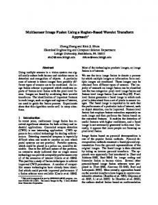
Figure 1: BM3D-based image fusion algorithm flow chart.
block-matching spatial fusion (BMSF). The experimental results show that the multifocus image fusion results on both subjective visual quality and objective evaluation of this method are better than those of some existing state-of-the-art image fusion algorithms.
Step 4. The following coefficient fusion rules are presented in this algorithm:
2. Image Fusion Algorithm Based on BM3D The different purposes between the image fusion and the image denoising are considered when the first stage of BM3D [14] is conducted in this paper; in other words, we need not implement the second stage of BM3D. The image fusion algorithm is as follows. Step 1. Given two images, A and B, which have been well registered with different focus, the input images A and B are divided into several overlapping blocks, Γ𝑎∈𝑋 and Δ 𝑏∈𝑋 , respectively, where 𝑋 is the set of the coordinates of each block and Γ𝑎∈𝑋 and Δ 𝑏∈𝑋 are both called reference blocks. Grouping operations are implemented on blocks Γ𝑎∈𝑋 and Δ 𝑏∈𝑋 according to the method in [14]; that is, those image blocks similar to Γ𝑎∈𝑋 and Δ 𝑏∈𝑋 are stacked and two 3D matrices are formed: Γ𝑎3D = grouping (Γ𝑎 ) , Δ3D 𝑏
= grouping (Δ 𝑏 ) .
=
𝑇 (Γ𝑎3D ) ,
̂ 3D = 𝑇 (Δ3D ) . Δ 𝑏 𝑏
𝛾=
{𝛼 , if 𝛼 ≥ 𝛽 ; 𝛾 ={ 𝛽 , if 𝛼 < 𝛽 . {
Step 3. Let 𝛼 and 𝛽 be the low-frequency coefficients of ̂ 3D , respectively. 𝛼 and 𝛽 are the high-frequency Γ̂𝑎3D and Δ 𝑏 ̂ 3D , respectively. coefficients of Γ̂𝑎3D and Δ 𝑏 The defocused patches do not have enough detailed information, such as texture and contour. After the 3D transform, the bigger magnitude high-frequency coefficients are usually from the well-focused patches. The purpose of image fusion is just to recover these pieces of detailed information. So we select the bigger magnitude coefficients as the fusion result high-frequency coefficients. On the other hand, there are very similar low-frequency transformed coefficients between the
(3)
Note. Only one low-frequency coefficient exists after the 3D transform of each 3D transform, whereas the rest are all highfrequency coefficients. The high-frequency coefficients to be fused are from the same location in each 3D transform. Step 5. 3D inverse transform is implemented on 3D coefficients matrix 𝐹̂𝑓3D that consists of 𝛾 as low-frequency coefficients and 𝛾 as high-frequency coefficients: 𝐹𝑓3D = 𝑇−1 (𝐹̂𝑓3D ) .
(4)
Step 6. Fusion image is obtained by aggregating all the image blocks in each group 𝐹𝑓3D . The particular aggregation formula is as follows: 𝐹 (𝑥) =
(2)
𝛼+𝛽 , 2
(1)
Step 2. Two 3D matrices grouped in Formula (1) are implemented with separable 3D transform to obtain their sparse representation: Γ̂𝑎3D
well-focused patches and the defocused ones, so we simply average the low-frequency coefficients which are from both the well-focused and defocused patches, respectively, as the fusion result low-frequency coefficients.
∑𝑥∈𝑋 𝐹𝑓3D (𝑥) ∑𝑥∈𝑋 𝜒 (𝑥)
,
∀𝑥 ∈ 𝑋,
(5)
where 𝐹 is the fused image, 𝜒 is the characteristic function, and 𝑋 is a set of coordinates constituted of all blocks. Figure 1 illustrates the algorithm flow chart. The flowchart presents a kind of direct BM3D-based algorithm for image fusion. In this paper, this algorithm is called BM3DF. The experimental results show that the fused result of BM3DF is not ideal on objective evaluation, although the subjective visual quality remains better than some existing algorithms. There may be some following reasons. Firstly, the high-frequency coefficients selection strategy of BM3DF is a little rough. Secondly, the image details from the well-focused image patches are always inevitably smoothed in some degree
Mathematical Problems in Engineering
Image A
Blockmatching
3
R-block DCT AC energy calculating or
Image B
Blockmatching
Fused image
Aggregating
R-block DCT
Figure 2: BMSF algorithm flow chart. Green block is the reference block (R-block).
Figure 3: BMSF algorithm diagram.
since the inverse 3D transform after the coefficients fusion and the final aggregation procedure. Thus, the fused result is not ideal on objective evaluation. If we use a good strategy to judge which image blocks are from the well-focused parts in advance, we only implement the block matching on those well-focused image blocks, and if we remove the 3D transform, we may obtain better objective evaluation. Therefore, a simpler but more effective image fusion algorithm than BM3DF is proposed, namely, block-matching spatial fusion (BMSF).
So we use AC energy of DCT to decide which patches are well-focused ones in advance. The BMSF algorithm is as follows. Step 1. Block matching is conducted, which is the same as Step 1 in Algorithm BM3DF. Step 2. DCT is implemented only on the two reference blocks. The AC energy of these blocks is calculated as follows: 𝑁
𝐸𝑎 = ∑ 𝑅 − 𝑅 (1, 1) ,
3. Block-Matching Spatial Image Fusion In this algorithm, we remove 3D transform, but the block matching and block aggregation are preserved. Thus, this algorithm can still avoid introducing artifacts and can obtain excellent objective evaluation results. The reason of preserving the block aggregation is to avoid presenting the image edge abrupt transition in the fused image; however, the image details in the well-focused patches are hardly impacted by those defocused ones. Although DCT cannot better represent image textures or contours than DWT or some super wavelets, we can well judge which patches are better focused only by its alternating component (AC) energy.
𝑖,𝑗=1 𝑁
(6)
𝐸𝑏 = ∑ 𝑅 − 𝑅 (1, 1) , 𝑖,𝑗=1
where 𝑅 and 𝑅 are the DCT coefficients of the two reference blocks and 𝑅(1, 1) and 𝑅 (1, 1) are their direct components. Step 3. If 𝐸𝑎 > 𝐸𝑏 , then we consider that Γ𝑎3D is from the wellfocused image, rather than Δ3D 𝑏 being from the well-focused image. By using this selection rule, we obtained all the wellfocused image block groupings, which are noted as 𝐹3D .
4
Mathematical Problems in Engineering
(a)
(b)
(c)
(d)
(e)
(f)
(g)
Figure 4: Clock image fusion result comparison. (a) and (b) are the two source images, (c) is the fusion result from [8], (d) is the fusion result from [18], (e) is the fusion result from [19], (f) is the fusion result of BM3DF, and (g) is the fusion result of BMSF.
Step 4. Fused image is obtained by aggregating all image blocks in each group 𝐹3D . The particular aggregation formula is as follows: 𝐹 (𝑥) =
∑𝑥∈𝑋 𝐹3D (𝑥) , ∑𝑥∈𝑋 𝜒 (𝑥)
∀𝑥 ∈ 𝑋,
(7)
where 𝐹 is the fused image, 𝜒 is the characteristic function, and 𝑋 is a set of coordinates composed of all blocks. Figure 2 illustrates the algorithm flow chart. We present the algorithm diagram in Figure 3 to show clearly the proposed algorithm.
4. Experimental Results In this section, many multifocus image fusion experiments are conducted based on the proposed two image fusion algorithms. Image fusion experiments are conducted by using “clock,” “disk,” and “lab.” These three are commonly used images in image fusion research fields. Two fusion criteria, mutual information (MI) [16] and QAB/F [17], are used to evaluate fusion performance [8, 18, 19]. Mutual information means MI(𝑋; 𝑌) = 0 if and only if 𝑋 and 𝑌 are independent random variables. In image fusion, MI is used to measure the amount of the same information between the source images
Mathematical Problems in Engineering
5
(a)
(b)
(c)
(d)
(e)
(f)
(g)
Figure 5: Disk image fusion results comparison. (a) and (b) are the two source images, (c) is the fusion result from [8], (d) is the fusion result from [18], (e) is the fusion result from [19], (f) is the fusion result of BM3DF, and (g) is the fusion result of BMSF.
and the fused image, and the higher MI value indicates the source images and the fused image sharing the more same information; QAB/F represents the preserved image details amount in the fused image, and the higher value of QAB/F means the fused image contains the more image details. Evaluation criteria listed in Table 1 demonstrate that the proposed BMSF algorithm can achieve the most consistent fused images to the source images and preserves the image edges best. We compare the two proposed algorithms with the classical image fusion algorithm PCNN [8], sharpness statistics (SS) [18], and state-of-the-art guided filtering (GF) [19] to show the advantages of the proposed algorithms in this paper. For the proposed methods, all the parameters of BM3DF are the same as those of BM3D. For BMSF, the size of image block is 17 × 17 and all the other parameters are the same as those of BM3D. As shown in Figures 4–6, PCNN leads to obvious blurred edges. SS generates very sharp edge but introduces artifacts around boundaries. GF produces good results but still encounters blurring around boundaries. The proposed approach achieves minimal artifacts around
the object boundaries and produces the sharpest images. However, BM3DF cannot achieve good objective evaluation results.
5. Conclusions The block-matching and nonlocal means algorithms are initially proposed to improve image denoising performance and have obtained a series of significant achievements. The most significant advantage of nonlocal method is that it can relieve and even avoid the artifacts introduction comparing some traditional transform domain methods. This paper proposed two multifocus image fusion algorithms which are called BM3DF and BMSF, respectively, under the revelation of nonlocal method. Although the subjective visual quality of the fused image by the BM3DF is better than some existing algorithms, the objective evaluation is not ideal yet. In fact, the image details from the well-focused image patches are always inevitably smoothed in some degree since the inverse 3D transform after the coefficients fusion and the final aggregation procedure.
6
Mathematical Problems in Engineering Table 1: Comparison of the MI and QAB/F results among the proposed algorithms and algorithms from references [8, 18, 19].
Images Disk Lab Clock
MI 6.15 7.59 7.47
PCNN QAB/F 0.656 0.700 0.681
SS MI 7.55 8.04 8.03
GF QAB/F 0.715 0.740 0.693
MI 7.06 7.91 7.89
QAB/F 0.724 0.751 0.716
MI 5.97 7.10 6.75
BM3DF QAB/F 0.672 0.711 0.654
(a)
(b)
(c)
(d)
(e)
(f)
BMSF MI 7.73 8.37 8.21
QAB/F 0.731 0.756 0.721
(g)
Figure 6: Lab image fusion results comparison. (a) and (b) are the two source images, (c) is the fusion result from [8], (d) is the fusion result from [18], (e) is the fusion result from [19], (f) is the fusion result of BM3DF, and (g) is the fusion result of BMSF.
In order to obtain the good visual quality and the ideal objective evaluation simultaneously, we use a good strategy to judge which image blocks are from the well-focused parts in advance; we only implement the block matching on those well-focused image blocks and remove the 3D transform thus obtaining better objective evaluation; that is, a simpler but more effective image fusion algorithm than BM3DF is proposed, and it is called BMSF in this paper. Some related references even pointed out that BM3D algorithm is too complex, but the running time of the BM3D program is not long at all comparing many existing image denoising algorithms; it usually takes less than 5 seconds
when a common grayscale image is processed in a core2 duo 2.66 GHz computer. Due to only using the first stage of BM3D in the BM3DF, the running time of BM3DF is significantly shorten; it takes only about 2 second when we fuse the “clock” images in our experiments. Furthermore, the BMSF removes the 3D transform in BM3D; the running time should be shorter. However, the image block size in BMSF is a little bit bigger than BM3DF, so the running time of the BMSF is nearly the same as the BM3DF. Experimental results have shown that the improved image fusion results can be achieved, although the proposed algorithm in this paper uses the simple fusion rules.
Mathematical Problems in Engineering
Conflict of Interests The authors declare that there is no conflict of interests regarding the publication of this paper.
Acknowledgments This work was supported by the National Science Foundation of China under Grants nos. 61379015 and 61233011, the Natural Science Foundation of Shandong Province under Grant no. ZR2011FM004, and the Science and Technology Development Project of Tai’an City under Grant no. 20113062.
References [1] H. Chen and Y. Wang, “Research on image fusion algorithm based on Laplacian pyramid transform,” Laser and Infrared, vol. 39, no. 4, pp. 439–442, 2009. [2] G. Cheng, L. Guo, Y. Zhao et al., “A multi-focus image fusion method based on wavelet transform,” Computer Engineering and Applications, vol. 48, no. 1, pp. 194–196, 2012. [3] X. L. Zhu, Q. Z. Wu, and H. Chen, “Dual-band infrared image fusion method based on wavelet transform,” Laser and Infrared, vol. 44, no. 5, pp. 572–576, 2014. [4] Y. Gao, A. Wang, and F. Wang, “Application of improved wavelet transform algorithm in image fusion,” Laser Technology, vol. 38, no. 5, pp. 690–695, 2013. [5] F. Lulu and A. Chengbin, “Research on image fusion lifting based on LWT,” Laser and Infrared, vol. 42, no. 9, pp. 1076–1079, 2012. [6] Z. Zhao and Y. Zheng, “Research of image fusion of multispectral and panchchromatic images based on ridgelet transform,” Computer Engineering and Applications, vol. 48, no. 15, pp. 164– 167, 2012. [7] Y. Yang, D. Ming, and Z. Luoyu, “Uniform discrete curvelet transform for multi-focus image fusion,” Infrared and Laser Engineering, vol. 42, no. 9, pp. 2547–2552, 2013. [8] X.-B. Qu, J.-W. Yan, H.-Z. Xiao, and Z.-Q. Zhu, “Image fusion algorithm based on spatial frequency-motivated pulse coupled neural networks in nonsubsampled contourlet transform domain,” Acta Automatica Sinica, vol. 34, no. 12, pp. 1508–1514, 2008. [9] X. Qu, J. Yan, G. Xie, Z. Zhu, and B. Chen, “Novel image fusion algorithm based on bandelet transform,” Chinese Optics Letters, vol. 5, no. 10, pp. 569–572, 2007. [10] W. Liu, M. Yin, J. Luan, and Y. Guo, “Image fusion algorithm based on shift-invariant shearlet transform,” Acta Photonica Sinica, vol. 42, no. 4, pp. 496–503, 2013. [11] A. Buades, B. Coll, and J. M. Morel, “A review of image denoising algorithms, with a new one,” Multiscale Modeling & Simulation, vol. 4, no. 2, pp. 490–530, 2005. [12] A. Buades, B. Coll, and J.-M. Morel, “Nonlocal image and movie denoising,” International Journal of Computer Vision, vol. 76, no. 2, pp. 123–139, 2008. [13] T. Brox, O. Kleinschmidt, and D. Cremers, “Efficient nonlocal means for denoising of textural patterns,” IEEE Transactions on Image Processing, vol. 17, no. 7, pp. 1083–1092, 2008.
7 [14] K. Dabov, A. Foi, V. Katkovnik, and K. Egiazarian, “Image denoising by sparse 3-D transform-domain collaborative filtering,” IEEE Transactions on Image Processing, vol. 16, no. 8, pp. 2080–2095, 2007. [15] Y. Hou, C. Zhao, D. Yang et al., “Comments on ‘image denoising by sparse 3-D transform-domain collaborative filtering’,” IEEE Transactions on Image Processing, vol. 21, no. 1, pp. 268–270, 2012. [16] Y. Chai, H. Li, and Z. Li, “Multifocus image fusion scheme using focused region detection and multiresolution,” Optics Communications, vol. 284, no. 19, pp. 4376–4389, 2011. [17] Y. Chai, H. F. Li, and J. F. Qu, “Image fusion scheme using a novel dual-channel PCNN in lifting stationary wavelet domain,” Optics Communications, vol. 283, no. 19, pp. 3591–3602, 2010. [18] J. Tian and L. Chen, “Adaptive multi-focus image fusion using a wavelet-based statistical sharpness measure,” Signal Processing, vol. 92, no. 9, pp. 2137–2146, 2012. [19] S. Li, X. Kang, and J. Hu, “Image fusion with guided filtering,” IEEE Transactions on Image Processing, vol. 22, no. 7, pp. 2864– 2875, 2013.
Advances in
Operations Research Hindawi Publishing Corporation http://www.hindawi.com
Volume 2014
Advances in
Decision Sciences Hindawi Publishing Corporation http://www.hindawi.com
Volume 2014
Journal of
Applied Mathematics
Algebra
Hindawi Publishing Corporation http://www.hindawi.com
Hindawi Publishing Corporation http://www.hindawi.com
Volume 2014
Journal of
Probability and Statistics Volume 2014
The Scientific World Journal Hindawi Publishing Corporation http://www.hindawi.com
Hindawi Publishing Corporation http://www.hindawi.com
Volume 2014
International Journal of
Differential Equations Hindawi Publishing Corporation http://www.hindawi.com
Volume 2014
Volume 2014
Submit your manuscripts at http://www.hindawi.com International Journal of
Advances in
Combinatorics Hindawi Publishing Corporation http://www.hindawi.com
Mathematical Physics Hindawi Publishing Corporation http://www.hindawi.com
Volume 2014
Journal of
Complex Analysis Hindawi Publishing Corporation http://www.hindawi.com
Volume 2014
International Journal of Mathematics and Mathematical Sciences
Mathematical Problems in Engineering
Journal of
Mathematics Hindawi Publishing Corporation http://www.hindawi.com
Volume 2014
Hindawi Publishing Corporation http://www.hindawi.com
Volume 2014
Volume 2014
Hindawi Publishing Corporation http://www.hindawi.com
Volume 2014
Discrete Mathematics
Journal of
Volume 2014
Hindawi Publishing Corporation http://www.hindawi.com
Discrete Dynamics in Nature and Society
Journal of
Function Spaces Hindawi Publishing Corporation http://www.hindawi.com
Abstract and Applied Analysis
Volume 2014
Hindawi Publishing Corporation http://www.hindawi.com
Volume 2014
Hindawi Publishing Corporation http://www.hindawi.com
Volume 2014
International Journal of
Journal of
Stochastic Analysis
Optimization
Hindawi Publishing Corporation http://www.hindawi.com
Hindawi Publishing Corporation http://www.hindawi.com
Volume 2014
Volume 2014