locher et al Huttenlocher and Ullman, 1990] for the pose ... formulation of Ullman Ullman, 1986]. ..... Grimson et al., 1992] W. Eric Grimson, Daniel P. Hut-.
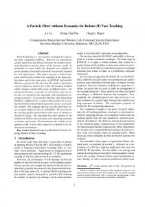
Bounding Errors for Improved 3D Face Tracking in Visual Interfaces Jochen Heinzmann and Alexander Zelinsky
Robotic Systems Lab Research School of Information Sciences and Engineering The Australian National University, Canberra ACT 0200 [jochen alex]@syseng.anu.edu.au j
Abstract
This paper describes recent results in a humanrobot interaction project. The aim of the project is to develop human-friendly robots, in particular control systems and user interfaces for such systems. In this paper we present an error analysis of the visual face tracking system that has been developed as an interface appropriate for natural interaction between a robot and an operator. The system utilizes a monocular camera and a hardware vision system to identify features of a face and estimate the 3D pose of the head.
1 Introduction
If robot technology is to be introduced into the everyday human world, the technology must not only operate ef ciently executing complex tasks such house cleaning or putting out the garbage, the technology must be safe and easy for people to use. This requires a human-machine interface that lets people interact with the robot in a natural way. People naturally express themselves through language, facial gestures and expressions. Speech recognition in controlled situations using a limited vocabulary with minimal background noise interference is now possible and could be included in human-robot interfaces. However, vision-based human-computer interfaces have only recently begun to attract considerable attention. With a visual interface a robot could recognize facial gestures such as "yes" or "no", as well being able to determine the user's gaze point i.e. where the person is looking. The ability to estimate a person's gaze point is most important for a human-friendly robot. For example a robot assisting the disabled may need to pick up items that attract the user's gaze. The face tracking system described in this paper will be connected to a Barrett WAM (Whole Arm Manipulator) robot arm. In a desktop con guration a person will be able to select a particular object on the table with his/her gaze and
command the robot to pick it up and hand it over. Facial gestures will be used for error correction, such as a nod to con rm the selection of the correct object or shaking the head to indicate that the wrong object was selected. In this paper we report an accuracy evaluation of a realtime vision based interface that tracks a persons head with a monocular camera and estimates the 3D pose.
2 3D Pose Recovery
The recovery of the pose of objects is one of the fundamental algorithms in computer vision. In particular for rigid objects a variety of solutions has been proposed. Methods that only use as many object points as necessary to restrict the problem in a way that yields only one accurate solution are widely used. Over constraining the problem by including additional object points usually leads to computationally expensive least squares minimization problems. See [Koller et al., 1993][Lowe, 1991] for iterative solutions and [Arun et al., 1987][Horn, 1987] for closed form solutions. Since the spatial position of three object features describe the pose of a rigid object in space, a variety of algorithms have been developed using feature triplets. There are two major classes of solutions, those assuming a�ne projection and those assuming perspective projection of the object points. The perspective projection is the most accurate model however systematic errors are introduced by di�erences between the camera lens system and the assumption of a pinhole camera. [Haralick et al., 1991] gives an overview of the algorithms assuming perspective projection. The a�ne projection has various advantages, as the calculations are signi cantly simpler and therefore better suited for real-time applications. The focal length does not need to be known if only the rotational aspect of the pose is of interest. Instead of the four solutions produced by perspective projection solutions the a�ne projection has only two solutions for a given projection of a feature triplet. In many cases the use of the a�ne projection can be justi ed by the large distance between the object and the camera relative to the minor di�erences
in depth of the features. In such cases the di�erence between the solutions using the a�ne projection model and the perspective model are negligible. As a rule of the thumb the ratio between the distance of the object from the camera and the depth di�erences of the individual features should be at least 10:1 [Costall, 1993][Gee and Cipolla, 1994][Thompson and Mundy, 1987]. Algorithms proposed to solve the three-point to 3Dpose problem include Ullman's [Ullman, 1986], Huttenlocher and Ullman's [Huttenlocher and Ullman, 1990], Grimson, Huttenlocher and Alter's [Grimson et al., 1992], Alter's [Alter, 92] and Cygnaski and Orr's [Cyganski and Orr, 1988]. Alter [Alter, 92] described a brief analysis of the numerical stability of his algorithm. Grimson et al [Grimson et al., 1992] made an error analysis of the Huttenlocher and Ullman algorithm, which we also consider. Grimson et al derived bounds for the error in the nal result bounded by an �-circle around the precise position. The calculation of the error propagation through the algorithms is complex and only rough overestimates can be derived. Also, Grimson et al made no attempt to derive the systematic error introduced by assuming a�ne projection nor did they try to improve the accuracy of the algorithm. For our face tracking application [Zelinsky and Heinzmann, 1998] we chose the algorithm proposed by Huttenlocher et al [Huttenlocher and Ullman, 1990] for the pose recovery since it only produces the two real solutions of the pose recovery problem, in contrast to the original formulation of Ullman [Ullman, 1986]. In the following section we analyze the systematic error as well as the sensitivity of the estimate to tracking errors. Also we derive an extension using the error analysis to decrease the systematic error. This extension was implemented and experimentally evaluated. Results are presented in this paper.
3 Systematic Error
Our pose estimation algorithm assumes an a�ne projection of the model points into the image plane. In reality, the features are projected into the image plane under perspective projection. The systematic error caused by this discrepancy is analyzed in this section. We also propose an improvement to the feature triplet pose recovery algorithm that is able to reduce the systematic rotational error of the pose estimate by 75% and the maximum translational error by 90%. The well known formulas for pose recovery are stated for completeness, for a description of the underlying geometry refer to [Huttenlocher and Ullman, 1990][Alter, 92]. L = N2 � M?2 1 (1) 2�2 where N2 IR contains the image positions n2 and n3 in it's columns and M2 2IR2�2 contains the x- and y-
components of the model points in it's columns. In the next step a digression is made to consider how two orthogonal and equal length vectors u1;2 are transformed. Choosing u1;2 2IR2 to be (1,0) and (0,1), k1 and k2 become � � � � (2) k1 = ? ll11 � ll12
�
k2 =
ll11 21 s �
21
�
�
�
22
l12 l22
�
� q c1 = � 12 k2 + k22 + 4k12 � k1 0 c2 = �c1p?k cc1 6= = 0 2 1 q
q
(3) (4) (5)
2 2 2 2 + l21 + c21 = l12 + l22 + c22 (6) s = l11 2 3 l11 l12 1s (c2l21 ? c1l22 ) sR = 4 l21 l22 s1 (c1l12 ? c2l11 ) 5 (7) c1 c2 s1 (l11l22 ? l12l21 ) As a metric for the rotational error between two spatial orientations we use the angle in the equivalent angle-axis representation as de ned by Craig [Craig, 1986]. We de ne the rotational distance metric �(P1; P2) as the angle in this representation: � 0 P1;1 + P02;2 + P03;3 ? 1 � (8) �(P1; P2) = arccos 2 where P0 = P?1 1�P2 is the transformation from P2 to P1. The rotational di�erence between the true orientation P1 and the measured orientation P2 is plotted over the angles �x and �y of the rotations about the x- and yaxes in Figure 1a using the original Huttenlocher and Ullman algorithm. The calculations are based on the model and distances shown in Figure 3 which resembles the situation in our face tracking application. The angle �z of the rotation about the z-axis equals 0. The rotational error varies strongly over the visible range of the triplet plane. The four big humps are generated by strong errors in the estimation of the third elements of the rst two column vectors p1 = s1 [l11; l21; c1]t and p2 = s1 [l12; l22; c2]t of the rotation matrix M2 , corresponding to the z-component of the new x- and y-axes. If the image coordinates of the features are generated by an a�ne projection, the rst two column vectors p1;2 have equal length. Thus, s scales both p1 and p2 to length 1. However, feeding the algorithm with feature coordinates generated by a perspective projection, the length of the rst two column vectors is generally di�erent, corresponding to two di�erent depth estimates that can be derived from the two columns. q q 2 2 2 2 s1 = l11 + l21 + c21 6= l12 + l22 + c22 = s2 (9)
0.8
0.8
0.6
0.6
0.4
0.4
0.2
0.2
0 -1.5
-1
-0.5
0 thy 0.5
1
1.5 1.5
1
-1 -0.5 0 0.5 thx
-1.5
a)
0 -1.5
-1
-0.5
0 thy 0.5
1
1.5 1.5
1
-1 -0.5 0 0.5 thx
-1.5
b)
Figure 1: The systematic rotational error in the pose recovery plotted over the rotational angles �x and �y about the x- and y-axes. Plot a) shows the error for the original algorithm, plot b) for the improved version. The correct value s~ lies between s1 and s2 . Choosing s = max(s1 ; s2) as the normalization and depth estimation parameter in Equation 7 can reduce the maximum error in the depth estimate to about 10% of the original maximum error. Simply scaling the unused column pj to length 1 generates a valid rotation matrix. Obtaining a more accurate scaling value s gives rise to a more accurate estimate of the z-component of pj . This allows us to reduce the systematic rotational error by 75%. Since the rst two elements of that vector and the scaling are already determined, only the third element of pj , cj , can be recomputed such that pj has length 1. This recalculation changes the orientation of the vector, thus, pi and pj are no longer orthogonal. The third element of pi has to be recomputed such that pi and pj are orthogonal, and then pi can be scaled to length 1. The third column p3 of the rotational matrix R is generated according to the original algorithm to complete the matrix. The extensions to the original algorithm are outlined below: 1. Calculate L, k1, k2, c1 and c2 according to the formulas 1-5. 2. p Calculate the length ofp both columns s1 = 2 2 2 2 l11 + l21 + c21 and s2 = l12 + l22 + c22 3. Let i; j be indices such that si � sj . Then the scaling factor can be determined from the length of the longer vector s = si . 4. Recalculate cj to make column s1 pj to be length 1 preserving the sign of cj .
5. Recalculate ci so that pi ? pj (R) and rescale pi so that s1 pi is of length 1; 6. Calculate the third column or R using Formula 7. The resulting rotational error of the rotation matrix obtained from the improved algorithm is shown in Figure 1b. The extensions to the algorithm reduce the rotational error to about 25% of the error obtained from the original algorithm.
4 Tracking Error Sensitivity
In control theory sensitivity is a widely used term that describes the change in a parameter a as result of changes in a parameter b. The sensitivity function describes the fractional change in a, due to b, divided by the fractional change in a [Anand and Zmood, 1995]. We de ne the sensitivity &r in respect to the rotational part of the pose estimation to tracking errors for a particular pose P as the 2-norm of the vector of the di�erential quotients of the orientation distance function �.
2
&3 3
6 &4 7 6
7 &r (P) = 4 & 5
(10)
5
&6 2 1 �(p(N(P)); p(N(P) + �vi )) (11) &i = �lim !0 � where N(P) is the vector of projected image positions, p(N(P)) is the recovered pose from this projection and vi is the error vector for the ith element. The rotational sensitivity &r of the model triangle over [�x; �y ] is plotted in Figure 2a. The spike in the center reaches up to in nity since the partial derivatives
0.2 0.2
0.15
0.15 0.1
0.1
0.05 0 -1.5
0.05
-1 -0.5 0 thy 0.5 1
1.5 1.5 1
0.5 0thx
-1.5 -0.5 -1
a)
0 -1.5
0.5 -1
-0.5
0 thx 0.5
1
-1
0 -0.5 thy
1.5 -1.5
b)
Figure 2: The sensitivity of the estimated pose over the rotations about the x- and y-axes. Plot a) shows the sensitivity for a single triangle and plot b) for the combination of two triangles of the projected position of the features in respect to �x and thetay equals 0 at this point. The plot gives a good impression where the pose estimate will be robust and where noise with large standard deviation will occur. Figure 2b shows the reduced sensitivity which can be achieved by using multiple feature triplets.
5 Using Multiple Triplets
The pose recovery of a feature triplet under a�ne projection has a twofold ambiguity. Two poses P1 and P2 generate the same projection which correspond to a re ection about a plane parallel to the image plane. In our discussion of the systematic errors we assumed that we can always determine the correct solution P^ for the pose. The ambiguity can be resolved by using 2 feature triplets in non-parallel planes as indicated in Figure 4. Both triplets generate two solutions, but only one solution is consistent with both triplets. This solution corresponds to the correct pose P^ of the object. However, when using two triplet planes even without noise the two correct solutions in general do not perfectly match. A straight forward solution to the problem is to weight the two almost matching solutions according to their sensitivity. The equivalent angle-axis formulation provides a mechanism to directly interpolate between two spatial orientations by rotating only a fraction of the angle around the equivalent axis K . !
^ P = EAR P^ 1; P^ 2; &r (P^2) � �(P1^; P2) � P^ 1 (12) &r (P1) + &r (P2)
where EAR(P^ 1 ; P^ 2; �) is the rotational matrix around the equivalent axis k of P^ 1 and P^ 2 with angle � and &r (P) is the rotational sensitivity of P. However, by doing so the available information is not used in an optimal way. The sensitivity is a good measure of the overall error that can be expected from a particular pose estimate. But di�erent components of the pose estimates have di�erent individual sensitivities. Considering Figure 3, it is intuitively obvious that rotations about the z-axis can be detected very well in the frontal view, whereas rotations about the x- and y-axes prove to be di�cult. By de ning individual sensitivities for each of the rotational components allows us to synthesize a better spatial orientation P from multiple measurements which gives a lower overall sensitivity. We de ne the metrics �x ; �y and �z for the rotations about the three axes as the absolute di�erence between their respective rotations in the spatial orientations P1 and P2. �x (P1; P2) = jRotx (p(P1)) ? Rotx (p(P2 ))j (13) �y and �z are de ned in a similar way. Similarly to the metrics, we de ne the sensitivity functions &x , &y and &z for the individual components of the spatial transformation. The individual components of the spatial transformation P describing the overall pose of the object can now be easily derived. Each rotation Rotx;y;z (P) about the three axes is the weighted average of the two respective rotations in P1 and P2 with the sensitivity as weights. Equation 14 gives the rotation around the x-axis, the formulas for the y- and z-axes can be similarly derived.
m3
y
m1
x
50mm
m2
60 0m m
z
50mm
image plane
y
z focal point
x Axis 2
z
x Axis 1
y
Figure 3: The geometry of the model triplet used for the accuracy and sensitivity evaluations. XP xP 1 &x (P1 )
x (P2 ) + Rot &x (P2 ) Rotx (P) = (14) + &x (1P2 ) The resulting sensitivity for the overall pose estimate using the original model triplet and an additional triplet of the same shape but rotated 45� around the y-axis. This situation is similar to our face tracking application we discuss in the next section. Figure 2b shows the sensitivity for estimate derived from the combined triplets. The spike in the center of the graph in Figure 2a has been eliminated by the combination of two triplets. The two remaining smaller humps represent the spikes of the individual triplets. When combining two triplets the angle between their spatial normals should be su�ciently large so that their individual sensitivity spikes are separated in the object orientation space since the sensitivity of the combined pose is at least as high as the lowest individual sensitivity. Rot ( 1 ) & ( 1)
6 Experimental Results
The visual feature tracking and pose estimation was evaluated using the MARITA-system (MAnnequin Robot for Investigation of Tracking Accuracy). MARITA consists of a mannequin head mounted onto a cable driven high performance pan-tilt-device. The two degrees of freedom can rotate the head around it's vertical axis as well as tilt the head for- and backward. Rotations about the z-axis (facial normal) are not possible, however, the error in estimating this xed angle can still be measured. Also the transformation from the X-Y euler angles of the mechanism to the Z-Y-X euler angles used for the internal pose representation causes small rotations about the z-axis. MARITA allows us to position the mannequin head to an accuracy better than 0.1� and test the accuracy of the pose estimate of the face tracker under realistic conditions.
Figure 4: Outside view of the MARITA system with the rotational joints and head coordinate system. The white crosses indicate the feature positions, the triangles the triplet planes. 6.1
Features
6.2
Tracking results
To track the pose of the mannequin head a set of 19 features was selected manually, including 6 features per eye area, 3 features in the mouth area and 2 features in each ear area. The white crosses in Figure 4 denote the features used for tracking. Not all 19 features are used for pose estimation. Instead, only six features located at the corners of the triangles in Figure 4 are used to estimate the 3D pose. The other features are providing more clues for visual feature tracking which makes the overall tracking more stable and robust to noise and partial occlusions. With this selection of features and model triangles the spatial orientation of the head can be measured by at least two triplets for a wide range of con gurations. To measure the accuracy parameters of our face tracker we connect it directly to the controller of MARITA. A supervisory program moves the head into di�erent position and then a sample of the pose estimators performance is taken over a period of 500 frames. As parameters for the performance the bias (mean error) between the correct pose and the measured pose as well as the standard deviation of this pose are measured. These parameters closely relate to the systematic error and the sensitivity. The points for evaluation are spaced 0.1rad apart, ranging from -0.5 to 0.5rad in y-rotation and -0.3 to 0.3rad in x-rotation. Overall 77 positions are evaluated. Figure 5a and b show the mean absolute bias of the measured rotations about the y- and z-axes. The bias in most areas is close to 0 which indicates good performance of the pose estimator. On the edges of the plot where the head was rotated around the y-axis about 30� , the nonnormalized template tracking failed and abrupt changes
0.4
0.4
0.2
0.2
0
0 0.3 0.2 0.1
-0.2 -0.4 0.4
0.2
0 thy
-0.2
-0.4
0 -0.1thx -0.2 -0.3
0.3 0.2 0.1
-0.2 -0.4 0.4
0.2
a)
0 thy
-0.2
-0.4
0 -0.1thx -0.2 -0.3
b)
Figure 5: Performance measurements of the spatial orientation estimate: The bias of the measurements of the rotation a) about the y-axis (Roty ) and b) about the z-axis (Rotz ). in the magnitude of the error occur. The mean absolute biases were 0.06699rad (3.8�) in 75% of the area for the y-rotation and 0.04075rad (2.3�) in 74% for the rotation around the z-axis. The estimate of the rotation around the x-axis contains the highest error of the three axes because it is highly dependent on correct tracking of the features around the ear. Those features proved to be di�cult to track due to the lack of unique texture. The mean absolute bias in the area where the features were tracked successfully (68%) is 0.10479rad (6.0� ) for the x-axis. Overall, the mean absolute bias of the equivalent axis angle distance was 0.14098rad (8.1�) on 68% of the area.
7 Conclusion
We have presented a 3D pose estimation system from monocular image sequences based on the three feature triangulation algorithm by Huttenlochen and Ullman. To address the problem of systematic errors caused by measurements from perspective projections a improved algorithm has been proposed which reduces the systematic error in the examples by 75%. The problem of high sensitivity of certain components of the spatial transformation to tracking error has been overcome by using a sensitivity model and multiple triangles in di�erent special planes to derive a robust estimate. The algorithm has been implemented in our face tracking application for performance evaluation. Over a wide range of spatial orientations the derived estimates are stable and provide reasonable accuracy for a monocular system. For large rotations the performance of the system is mainly lim-
ited by the ability of the template based feature tracking system to reliably localize the features. More recent vision hardware makes brightness normalized correlation functions available which overcomes this problem.
References
[Alter, 92] Tao Daniel Alter. 3d pose from three corresponding points under weak-perspective projection. Technical Report AIM-1378, MIT, AI Lab, July 92. [Anand and Zmood, 1995] D K Anand and R B Zmood. Introduction to Control Systems. ButterworthHeinemann Ltd, Oxford, 3 edition, 1995. [Arun et al., 1987] K. S. Arun, T. S. Huang, and S. D. Blostein. Least squares tting of two 3d point sets. IEEE Trans Pattern Analysis and Machine Intelligence, 9(5):698{700, September 1987.
[Costall, 1993] A. Costall. A cubist manifesto for visual science. Image and Vision Computing, 11(6):334{341, 1993. [Craig, 1986] John J. Craig. Introduction to Robotics. Addison Wesley, 2 edition, 1986. [Cyganski and Orr, 1988] D. Cyganski and J. A. Orr. Object Recognition and Orientation Determination by Tensor Methods. Advances in Computer Vision and Image Processing, 3:101{144, 1988. [Gee and Cipolla, 1994] A.H. Gee and R. Cipolla. Nonintrusive gaze tracking for human-computer interaction. In Proceedings of the International Conference on Mechatronics and Machine Vision in Prac-
tice, pages 112{117, Toowoomba, Australia, Septem-
ber 1994. [Grimson et al., 1992] W. Eric Grimson, Daniel P. Huttenlocher, and T. D. Alter. Recognizing 3D ojbects of 2D images: An error analysis. Technical Memo AIM1362, Massachusetts Institute of Technology, Arti cial Intelligence Laboratory, July 1992. [Haralick et al., 1991] R. M. Haralick, C. Lee, K. Ottenberg, and M. Nolle. Analysis and solutions of the three point perspective pose estimation problem. In Proc. IEEE Conf. on Computer Vision and Pattern Recognition ICPR, pages 592{598, Los Alamitos, CA, USA,
1991. IEEE Computer Society Press. [Horn, 1987] B. K. P. Horn. Closed-form solution of absolute orientation using unit quaternion. Journal Optical Soc. Am., 4(4):629{642, 1987. [Huttenlocher and Ullman, 1990] D. P. Huttenlocher and S. Ullman. Recognizing solid objects by alignment with an image. International Journal of Computer Vision, 5(2):195{212, November 1990. [Koller et al., 1993] D. Koller, K. Danilidis, and H.-H Nagel. Model-based object tracking in monocular image sequences of road tra�c scenes. International Journal of Computer Vision, 10(3):257{281, 1993. [Lowe, 1991] D.G. Lowe. Fitting parameterized threedimensional models to images. IEEE Transactions on Pattern Analysis and Machine Intelligence, 13(5):441{ 450, 1991. [Thompson and Mundy, 1987] D. W. Thompson and J. L. Mundy. Three-dimensional model matching from an unconstrained viewpoint. In Proc. IEEE Robotics and Automation, pages 208{220, April 1987. [Ullman, 1986] S. Ullman. An approach to object recognition: Aligning pictoral descriptions. AI Memo 931, MIT, 1986. [Zelinsky and Heinzmann, 1998] Alexander Zelinsky and Jochen Heinzmann. A novel visual interface for human-robot communication. Advanced Robotics, 11(8):827{852, 1998.