Bridging the gap between user requirements and configuration requirements Pietro Colombo
Pejman Salehi, Ferhat Khendek
Maria Toeroe
DiSTA, Università dell’Insubria Varese, Italy
[email protected]
ECE, Concordia University Montreal, Canada {pe_saleh, khendek}@ece.concordia.ca
Ericsson Inc, Montreal, Canada
[email protected]
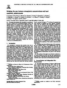
Abstract — The Service Availability Forum supports the realization of Highly Available systems by means of standards like the Availability Management Framework (AMF), a middleware service that manages the high availability of services provided by applications through the coordination of their redundant components. AMF configurations for applications, capable of providing and protecting services, can be generated from the software and from a set of configuration requirements (CR). The specification of CR requires a good knowledge of the AMF specification. Users/Customers may not have this AMF knowledge and are usually acquainted to specifying high level characteristics of services of interest. This paper introduces an approach aiming at bridging the gap between user requirements and configuration requirements for the design of AMF configurations. Keywords — High Availability; Configurations; Requirements analysis; Decomposition; Mapping.
I.
INTRODUCTION
Service high availability is becoming an important requirement in several domains. The Service Availability Forum 1 (SA Forum), a consortium of leading telecommunications and computing companies, has defined several standards to support the delivery of Highly Available (HA) systems [1]. These standards aim at reducing the cost and time of development and delivery by shifting availability management from applications to a dedicated middleware. Among these standards, the Availability Management Framework (AMF) [2] is a middleware service that manages the high availability of applications through the coordination of their redundant components. To this aim AMF requires a configuration model for each application under its control. An AMF configuration describes an application in terms of logical entities representing services and service provider resources. Each service imposes a specific workload on service provider entities. AMF attains service availability by orchestrating the workload assignments among redundant service provider entities. The application software to be configured by the designer and managed by AMF is described by the vendor in the Entity Types File (ETF) [6] in terms of entity prototypes. ETF prototypes characterize the deployment options, constraints and limitations of the software. The design of AMF configurations for meeting the user requirements (UR) for the provisioning of services from 1
http://www.saforum.org
these software descriptions and deployment infrastructure (nodes) is a real design challenge because of the large gap between the concepts involved in this design process and the complexity of the configurations. In previous work [3, 4, 5] we tackled the problem by introducing a new artefact, called Configuration Requirement (CR) model, which describes AMF middleware requirements for a given application. CR model specifies the services to be provided and protected as well as their properties using AMF specification jargon in contrast to the UR that express the customer’s/user’s expectations in terms of functional and non-functional (NF) characteristics of the services to be provided. The gap was smaller and this allowed us for automating the configuration design process. However, providing the input artefacts requires broad domain knowledge and expertise. Moreover, due to the lack of support for NF aspects in both AMF and ETF standards, CR model was exclusively based on functional aspects. For easing the work of configuration designers, in this paper we are proposing to start the process from the UR. For this purpose we need to bridge the gap between the UR and the CR and select the proper ETF software elements to be used for the AMF configurations. The benefits of this new approach are manifold. Particularly, it considers both the functional and NF aspects of UR, it alleviates the responsibilities of configuration designers, it promises to eliminate translation mistakes, and it speeds up the AMF configuration generation process. Moreover, it enables a greater involvement of the end user who has no or a limited knowledge of the AMF configuration jargon. The approach potentially leads to the definition of multiple sets of CR, and therefore to multiple AMF configurations that satisfy the UR. Moreover, it enables traceability all the way back to the end user requirements. The proposed approach is based on a framework that supports the modeling of UR, CR, the ETF functional and NF description of the software [12,13,14] as well as the AMF configuration generation approaches in [3,4,5]. Due to space limitation, in this paper we introduce the methodological guidelines without discussing the underlying modeling foundations. Our framework currently supports the modeling of NF properties concerning communication capabilities, like transfer rate. The guidelines and the main concepts of the involved domains are illustrated using a running example, the configuration of a LAMP server [7]. This example is used to ease the comprehension of the approach, which is meant to
be general and independent from this specific case study. The UR of LAMP specify the expectations of the user/customer with respect to the deployment of a web application. In this paper we use a simplified description of the LAMP bundle which consists of a web server (Apache HTTP Server), an interpreter for PHP scripting language (PHP5), and a DBMS (MySQL). The rest of the paper is organized as follows. In Section 2 we provide some basic concepts from the domain. In Section 3 we introduce our approach. Section 4 is devoted to related work before concluding in Section 5. Appendix A provides the list of acronyms used all through the paper. II.
BACKGROUND KNOWLEDGE
In this section we briefly introduce the basic concepts needed for the rest of the paper. A. The Entity Type Files (ETF). Vendors specify the characteristics, capabilities and limitations of their software with respect to AMF using ETF [6]. The approach presented in this paper relies on a new version [14] of the ETF model which extends the standard to support the NF characteristics of the software’s communication capabilities. The ETF description is given in terms of entity prototypes, data structures that specify the characteristics shared by multiple service and service provider entities. The basic entity prototypes are called Component Types (CompType) and Component Service Types (CSTypes). ETF CompTypes define the characteristics of the components of the SW bundle and CSTypes specify the characteristics of the workload of the services that can be provided/supported by these components. Additional and optional entity prototypes may be used to specify how these elements can be combined to provide higher level functionalities. More specifically, ETF CompTypes can be combined into ETF SUTypes, while ETF CSTypes can be combined into ETF Service Types (SvcTypes). ETF Service Group Types (SGType) group a set of SUTypes and model availability related features, such as the redundancy models, applicable to the instances of these SUTypes. Finally, ETF Application Type (AppType) aggregate one or many ETF SGTypes. The software description includes the NF characteristics of the communication capabilities for the provisioning of CSTypes by CompTypes. The specification considers the flow of data issued/received through the interfaces of the CompType/CSType pairs. The description also includes the specification of existing relationships among service provider entity prototypes when subjected to a specific workload. For instance, the CompType/CSType dependency specifies that a CompType for providing a CSType relies on the provisioning of a second CSType by a sponsor CompType. The dependency specification defines the types of data items and the NF characteristics of the data flow required and being handled by the sponsor. A further relation, denoted Communication, models the interaction between service provider entities through data flows while
providing their services, meaning that their I/O interfaces are compatible. The ETF model for the LAMP bundle is shown in Fig. 1 as a UML Class diagram. The stereotypes help to understand the role of the model elements. For instance, the Web server module of LAMP consists of CompTypes Apache2, Apache2Prefork, ApacheUtil, and ApacheModDnssd, which support CSTypes HttpService, StabilityOfService, UtilityService, and Httpd, respectively. The provisioning of CSTypes by CompTypes is modeled by means of stereotyped CtCst association classes. The model contains several examples of dependency and communication relationships. For instance, in providing HttpService, Apache2 depends on the provisioning of UtilityService by ApacheUtil. At the same time Apache2 in providing HttpService interacts with the interpretation service Php5CoreService supported by Php5. In Fig. 1 the NF characteristics of the flow of data is expressed informally with notes. Because of space limitation we do not show the structural specification of the types of the data items and consider as NF property only the volume of data expressed in terms of data units per second (u/s). For instance, Apache2 in providing HttpService can receive 250 u/s through its user interface UI. At the same time it can generate 200 u/s that are issued through the interfaces DI1, DI2 and DI3 to the sponsor peers of its dependency relationships (CompType/CSType ApacheMod-Dnssd/Httpd, Apache2Prefork/StabilityOfService and ApacheUtil/Utility-Service) and 200 u/s that are sent through interface CI to Php5/Php5CoreService. A similar scheme is used to characterize the NF requirements of the dependency relationships. For instance, the dependency between Apache2/HttpService and ApacheUtil/UtilityService requires components of the sponsor peer handle as input a volume of 200u/s. B. The Configuration Requirements for the Availability Management Framework Configuration requirements (CR) specify characteristics of the services to be provided by an application to be configured. An AMF configuration consists of AMF entities, which are logical entities representing services and service provider’s resources, and AMF entity types, which define the characteristics shared by multiple entities. In other words, AMF entity types specify the elements and the existing relationships between the elements of a certain installation of the software defined by ETF prototypes, while AMF entities model the characteristics of the processes instantiated from these AMF types. The basic AMF entities are called Components and represent resources capable of supporting Component Service Instances (CSI), namely the workload imposed by functionalities of the application’s services. Components are aggregated into Service Units (SU), logical entities representing the basic redundancy unit for AMF. The workloads of the components contained in an SU are aggregated into a Service Instance (SI), which represents the workload assigned to the SU. SUs are further grouped into Service Groups (SG) to protect a set of the provided SIs by means of redundancy models (‘No redundancy’, 2N, N+M,
Figure 1. The ETF model for LAMP
N-Way and N-Way-Active). Finally, AMF applications combine different SGs in order to provide the SIs protected by these SGs. Each SU is deployed on an AMF node and the set of all AMF nodes forms the AMF cluster. CR specify several properties of the AMF configuration including properties of the services, such as their types, the required number of instances of service entities, the relationships between these elements, and the redundancy models to protect them. The specification of CR is achieved with CSI and SI Templates that specify common characteristics shared by multiple instances of service entities. The CSI Template specifies the required CSType as well as the expected number of CSIs of that type. The SI Template specifies the SIs with the associated SvcType and the associated CSI Templates. Examples of CSI and SI templates are provided towards the end of Section 3 when we complete the application of the proposed approach to the running example. Requirements elicitation Requirements/Service analyst
Customer Software description Software Vendor
Ad-hoc specification of Configuration Requirements EntityTypes File (Standard)
Configuration Requirements
AMF Configuration Generation Availability Management Framework Configuration
Figure 2.
The original AMF configuration generation approach
III.
FROM USER REQUIREMENTS TO CONFIGURATION REQUIREMENTS
The design of an AMF configuration for a given application is a complex task that involves numerous entities, attributes and constraints. As mentioned earlier, in [3,4,5], the authors propose automated approaches to generate AMF configurations starting from ETFs, CR, and deployment infrastructure (nodes). The diagram in Fig. 2 shows a high level view of stakeholders and artifacts involved in [3,4,5]. These approaches represent a good step forward, but still suffer from the form of required CR expressed in terms of AMF concepts. Indeed, this can be seen as if the configuration designer is providing as input the service portion of the AMF configuration, without any explicit relation to the end user requirements. The goal of the work reported in this paper is the definition of a systematic approach that supports the specification of CR for the generation of AMF configurations. It aims at easing further the work of configuration designers, alleviating their responsibilities and speeding up the AMF configuration generation process. The proposed approach starts from the end user perspective and considers UR as input artifacts for the generation of AMF configurations. The approach derives the CR from the UR in a stepwise manner and in doing so it identifies the service provider entity types that will be used for AMF configuration generation. Fig. 3 provides a general view of the new approach and shows how it complements and enhances our previous version.
Requirements elicitation Customer Software description
Requirements/Service analyst Requirements analysis and specification
EntityTypes File (Extended)
User Requirements
Software Vendor
Systematic Derivation Guidelines Selected EntityTypes File prototypes
Configuration Requirements
AMF Configuration Generation
Availability Management Framework Configuration
Methodological contribution described in this paper New/ Enhanced artefact modeling support Artefact semantics and modeling support inherited from original process
Figure 3. The new AMF configuration generation approach
Our approach consists of 10 phases, guides the configuration designer through the analysis, specification and decomposition of UR, to the identification of the software entities capable of satisfying these requirements. The analysis criteria are based on dependency and interaction capabilities of the software entities. The required capabilities specified in the UR are compared to actual capabilities of the software bundle with the aim to identify the proper entity types and to estimate how many instances of software entities should be specified in the CR. Finally, CR are generated considering all the required properties. Therefore, the generated CR depend on the prototypes available in the ETF and their characteristics. 1) User requirements specification and decomposition The configuration designer, who is an expert in the service domain, is responsible for interacting with the customer to analyze his/her expectation with respect to the provisioning of the application services. Once this input from user completed, the configuration designer specifies the UR, refines and decomposes them into basic “modules”. For instance, let us assume that a customer is interested in deploying a HA Web application that can handle 1000 requests per second using LAMP. The configuration designer takes this UR, denoted Web Application, decomposes it into three modules called HTTP Server, Interpreter, and DBMS (see Fig. 4). NF properties are used to characterize both the original UR and the derived modules. The NF aspects of the original UR are mapped to the modules at the user interface. In the example, the volume of requests is mapped to the HTTP Server. The specification also captures the interactions and dependencies among the modules. In the example, HTTP Server needs to interact with Interpreter to request the interpretation of PHP scripts, and Interpreter, with DBMS to act on the DB.
2) Identification of the service entity prototypes capable of supporting the functionalities specified by the service module requirements In this phase the ETF model is exhaustively analyzed in order to identify the service entity prototypes compliant with the modules characteristics. The analysis is performed at the CSTypes level and may result in multiple alternative CSTypes for each module. Layer (2) of the diagram in Fig. 4 shows the result of the analysis of the ETF model of LAMP. CSTypes are represented by empty triangles. For instance, for module Interpreter, the selected CSType is Php5CoreService. 3) Identification of the service provider prototypes capable of providing the services. The service entity prototypes identified in the previous phase can be provided by different service provider prototypes. Therefore, it is required to select the CompTypes capable of providing the CSTypes identified for each module. The selection is performed through the exhaustive search of the ETF model and may result in a set of alternative CompTypes for each CSType, potentially with different NF characteristics. In Layer (3) of the diagram in Fig. 4, each CSType is provided by different CompTypes. The gray part of the triangle represents the CSType (matching the empty triangle of Layer (2)), while the black part represents the CompType. For instance, CompType MySQLClient is selected to support MySQLClientService and Apache2 to support HttpService. 4) Dependency analysis at CompType level The components and CSIs derived from the prototypes selected in previous phases may not be capable of supporting alone the functionality of each module. In this case, additional elements of other entity prototypes are required. The identification is achieved by means of the analysis of the dependency relationships of CompTypes contained in the ETF model.
Volume of requests: 1000 req/sec
User
(1) (2) (3) (4)
ExtHttp Server
Communicate FromTo Ext Interpreter Interpreter Http Service
Http Server
HttpService
Stability OfService Apache2 Prefork
(5) (6)
Interpreter Php5CoreService
(8) Httpd Apache ModDnssd
Communication
(8)
DBMS MySQLClientService
MySQLClientService MySQLClient
EmbeddableSQLService DataAccessAbstraction Php5Sqlite Php5Pdo
MySvcT1
MySUT1
Communicate FromTo Ext DBMS DBMS
Php5CoreService Php5
Communication
Apache2 Utility Service Apache Util
Web Application
MySvcT2 My SUT2
(7)
Communication
(8)
MySQLClientSvct Client MySQLEngine Server
Figure 4. First 8 phases of the approach applied to the running example
For instance, in the case where the CompTypes specify CompType/CSType dependencies we need to select the sponsor entity prototypes as well. This step is applied recursively to all the selected and added elements. Layer (4) of the diagram in Fig. 4 shows the result of the dependency analysis for our example. The selected elements are connected through links that model the dependency relationships. For instance, the pair Php5CoreService/Php5 depends on EmbeddableSQLService/Php5Sqlite and DataAccessAbstraction/Php5Pdo 5) Identification of the Service Types The pairs of CompType/CSType identified in Phase 3 are at the head of the graphs composed of a set of interdependent CompTypes/CSTypes. The CSTypes contained in these structures must be grouped into SvcTypes. Based on the ETF specification [6], several aggregation criteria specify if it is required to group the elements into a single or separate prototype(s). For example, all the CompTypes involved in a CSType/CompType dependency must be aggregated into the same SUType and the CSTypes into the same SvcType. Thus, a unique SvcType is required to group the CSTypes identified for the HTTP Server module since all the selected pairs are connected through CompType/CSType dependencies. The grouping criteria drive the selection of the required SvcTypes from the ETF model. In the case where the model contains at least one SvcType, this/these prototype(s) is/are selected. Otherwise, a new SvcType is defined to satisfy the grouping requirements. In the ETF model of Fig. 1, SvcType MySqlClientSvct aggregates one CSType, called MySqlClientService, which was selected for the DBMS module. Therefore, MySqlClientSvct is the proper ScvType for DBMS. Since no SvcType in the ETF model groups the CSTypes selected for the HTTP Server and the Interpreter modules, two SvcTypes have been defined. MySvcT1 has been generated to aggregate HttpService, UtilityService, StabilityService, and Httpd CSTypes. MySvcT2 has been defined to group PhpCoreService, EmbeddableSQLservice and
DataAccessAbstraction. Layer (5) of the diagram in Fig. 4 shows the selected SvcTypes. The generated types are represented by dashed gray rectangles, while the types identified in the ETF, as solid gray rectangles. 6)Identification of the SUTypes The SvcTypes selected in previous phase need to be provided by SUTypes capable of supporting their workload. It is therefore necessary to select these SUTypes. For each SvcType it is necessary to determine whether the ETF model contains an SUType capable of providing it. This SUType should aggregate all the CompTypes whose CSTypes were considered for the selection of the SvcType. For instance, in the case of module DBMS the required SUType should provide MySQLClientSvct and contain MySQLClient. Therefore, SUType Client is selected. If multiple SUTypes have been identified in the ETF model all the resulting types must be selected. Each alternative SUType may be used to generate a different set of CR. If the considered SvcType was created, the SUType cannot be found in the ETF model and it is necessary to define it. This is the case in our example for MySUT1 and MySUT2 because the supported SvcTypes MySvcT1 and MySvcT2 were created. Layer (6) of the diagram in Fig. 4 shows the selected SUTypes where solid rectangles represent identified prototypes and dashed rectangles represent the created ones. 7) Dependency Analysis at the SUType Level The SUTypes in providing their SvcTypes may depend on additional prototypes. Therefore, it is required to select the sponsor elements as well. More specifically, the ETF model specifies whether a given SUType requires another SvcType for providing a certain SvcType. This dependency requires the interfaces of the involved SUTypes/SvcTypes to be compatible, meaning the SUs of the involved SUTypes are capable of interacting with each other. Since SUs are logical entities that aggregate components, this interaction requirement is mapped to the component level. At least one couple of CompTypes/CSTypes grouped by the dependent SUType/SvcTypes has to be capable of interacting with at
least one couple of the sponsor. This happens when the flow of data generated by the sender CompType/CSType can be handled by the receiver since the structural and NF characteristics of the flow are compatible. The analysis of these dependencies may lead to the identification of dependent SUTypes/SvcTypes possibly affected by further dependencies, recursively. Therefore, the analysis is first applied to all the prototypes identified in Phase 6 and then it is recursively applied to the dependent elements. In our example the SUType Client requires MySQLEngine in order to provide MySQLClientSvct. The SUType Server is capable of providing MySQLEngine and Server is, therefore, selected. The result of the analysis is shown in Layer (7) of Fig. 4 where the dependencies are represented as lines connecting the selected entity prototypes. 8) Identification of interaction scenarios among modules The selected entity prototypes need to be refined based on the communication relationships defined between the modules, which require the respective selected prototypes to be capable of interacting with each other. The interaction capabilities of the entity prototypes guide the selection of the proper elements to be used for each module. The analysis considers one relationship at a time. For instance, let us consider the scenario shown in Fig. 5 where the UR has been decomposed into modules M1 and M2, and where M1 requires communication with M2. The entity prototypes selected for the modules are organized into alternative sets. The analysis considers all possible combinations of the sets of the two modules. The process starts focusing on the first set of M1 and M2, denoted M1S1 and M2S1. In the case where all the entity prototypes in the sets exist in the ETF model, the considered sets convey a valid interaction scenario if the entity prototypes of the input module include the SvcType at the head of the dependency chain of M2 (SvcT-B). As shown in Fig. 5, this case has been verified since SvcT-B is in M1S1 (it is marked with a star). The interaction has been captured by the dependency specified in the ETF model between the elements SUT-A/SvcT-A and SvcT-B. In the case where at least one of selected prototypes has been generated, the considered sets include the generated entity prototypes. In this case, the interaction requirements can be achieved if both the considered sets include at least one CompType/CSType capable of interacting with a peer in the other set. This condition is satisfied in our example by the entity prototypes selected for the Http Server and Interpreter modules. Both modules consist of one set of entity prototypes that have been created (i.e., MySvcT1, MySvcT2, MySUT1 and MySUT2). Therefore, the analysis focuses on the aggregated CompTypes/CSTypes. Apache2/HttpService can interact with Php5/Php5Core Service, therefore, the sets including these pairs meet the interaction requirements specified between HTTP Server and Interpreter modules, and are selected as part of a valid candidate scenario.
Once the first pair of sets of entity prototypes has been evaluated (M1S1-M2S1, in Fig. 5), the analysis shifts to another pair (e.g. M1S1-M2S2). The process is repeated, considering any possible combination of sets. Each scenario including sets of entity prototypes that satisfy the interaction requirements is selected. The analysis process is applied to each dependency interaction defined between the modules. Each application refines the set of entity prototypes, preserving only the ones that satisfy the UR. The analysis may identify multiple scenarios, each of which combines the set of entity prototypes that have been selected in each module. In our example, the process continues by considering the interaction requirements imposed between Interpreter and DBMS modules. The SUTypes/SvcTypes selected for Interpreter have been created, therefore it is required to focus the analysis at CompType/CSType level. In this case, the interaction requirement can be met through the communication relationship between MySQLClient/MySQLClientService and both Php5Sqlite/ EmbeddableSqlService and MySQLClient/MySQLClientService. Consequently, the sets of these types are selected. Fig. 4 illustrates the result of the interaction analysis applied to the modules of LAMP. Connectors marked with (8) link the entity prototypes that satisfy the interaction requirements. UR M1 CST-A1 CT-A1 CST-A2 CST-A3 CT-A2 CT-A3
M2
Communicate CST-B1 CT-B1 CST-B2 CT-B2
CST-C1 CT-C1
CST-D1 CT-D1
CST-C2 CT-C2
CST-D2 CT-D2
CST-C3
CT-C3
SvcT-A SUT-A
SvcT-B
SUT-E SvcT-B
SUT-B SvcT-C SUT-C
M1S1
SvcT-G
SvcT-E
SUT-G
SUT-B SUT-F SvcT-C SvcT-D SvcT-D SvcT-G SUT-C SUT-D SUT-G SUT-D SvcT-F
M1S2
M2S1
M2S2
Figure 5. Interaction analysis
9) Identification of the required number of CSIs of each selected CSType Once all the required entity prototypes are selected, it is required to calculate how many AMF service entities should be derived in order to satisfy the workload specified in the UR. The calculation is initially focused at CompType/CSType level, estimating the required number of CSIs of the CSType selected in each scenario. The calculation is based on the NF properties of the CompTypes in providing the CSTypes and of the module interfaces. Given an interaction scenario, the analysis starts considering the CompType/ CSType selected for the input module at the head of the chain of dependent elements (i.e., Apache2/HTTPService). The communication capabilities of
the CompType in providing the selected CSType are compared with the respective properties of the input module’s user interface. The aim is to estimate the minimum number of CSIs of that CSType, which can satisfy the requirements. The comparison criteria depend on the considered NF property. For example, for the data rate property considered in our example, the number can be estimated using equation (1).
CSIsCSType =
DataRateModule DataRateCompType CSType
(1) As already discussed in Section 2.1, in the ETF model for LAMP in Fig. 1, the data volumes capacity of CompTypes in providing CSTypes is shown by means of notes attached to CtCst association classes. For instance, pair Apache2/HttpService can handle as input a volume of 250 u/s from its user interface. Therefore, based on (1), since the demanded volume is 1000 u/s, the required number of CSIs of type HttpService is 4. The process continues by looking at the dependencies of the recently considered CSType/CompType. The dependency relation specifies the NF capabilities required to the sponsor pair. The ETF model is analyzed in order to extract information on the communication features of the sponsor CompType/CSType. For instance, as shown in Fig. 1, Apache2/HttpService in order to handle the data volumes requires ApacheUtil/ UtilityService capable of supporting 200 u/s. The properties that specify the capacity of the sponsor peer are compared to the equivalent properties required by dependency relationship. Equation (2) specifies the comparison criteria for the data rate property. Sponsor
CSIsCSType = Dependent CSIsCSType
Dependent
RequiredDataRateCompType
CSType
Sponsor
ProvidedDataRateCompType
CSType
Based on Equation (2), since in our example 1) we estimated 4 CSIs of type HttpService, 2) the data rate that instances of the couple ApacheUtil/UtilityService needs to handle is 200u/s, and 3) the rate at which this pair is able to support Apache2/HttpService is 100u/s, we determine the required number of CSIs of UtilityService as 8. The same criteria are applied to all the dependencies defined between CompType elements, identifying the number of CSIs of the involved CSTypes for all the CompType/CSType pairs selected for the input module. Table 1 shows the derived number of CSIs of CSTypes for module HTTP Server. TABLE I. TABLE 1. ESTIMATED NUMBER OF CSIS OF A GIVEN CSTYPE WHEN PROVIDED BY COMPONENTS OF COMPTYPES SELECTED FOR MODULE HTTPSERVER
CompType
CSType
Apache2 ApacheUtil Apache2Prefork ApacheModDnssd
HttpService UtilityService StabilityOfService Httpd
Min #CSIs 4 8 4 4
Once completed the intra-module interaction analysis, we look into the inter-module relationships. Thus, we consider the interaction between the modules HTTP Server and Interpreter achieved by Apache2/HttpService and Php5/Php5CoreService. The analysis compares the properties of the flow of data generated/expected by the pair of CompType/CSType belonging to the input module (pair A), with those of the pair of the related module (pair B). Equation (3) calculates the minimum number of CSIs of CSTypeB (the CSType of pair B) considering the data rate property. CompTypeB CSTypeB
CSIsCSTypeB
=
CompTypeA CSTypeA CSIsCSTypeA Output DataRateCompTypeA CSTypeA Input DataRateCompTypeB CSTypeB
,
Input CSTypeA Output DataRateCompTypeB CSTypeB
DataRateCompTypeA
Therefore, in our example, based on the interaction capabilities of Apache2/HttpService and Php5/Php5CoreService (see Fig. 1), 25 CSIs of type Php5CoreService provided by components of Php5 are necessary for the 4 CSIs of HttpService when provided by components of Apache2. The interaction analysis is automatically applied to each communication relationship that involves the entity prototypes selected for the input module. Afterwards, the entire dependency analysis is applied to the entity prototypes selected for other modules that interact with those of the input module. The required number of CSIs of the sponsor CSType in each dependency relationship is calculated taking into account the previously calculated number of CSIs necessary for satisfying the interaction requirements. In our example, since we estimated 25 CSIs of Php5CoreService, we require 25 CSIs of EmbeddableSQLService and 25 CSIs of DataAccessAbstraction when provided by components of type and Php5Sqlite and Php5Pdo, respectively. Finally, we apply again the interaction analysis described above considering the communication relationships that link the recently analyzed prototypes to those of other modules. Therefore, based on the communication relationship between Php5Sqlite/EmbeddableSQLService and MySQLClient/ MySQLClientService and the NF properties shown in Fig. 1, 7 CSIs of type MySQLClientService are required. The dependency and interaction analysis are recursively applied to the remaining entity prototypes of the considered scenario until we cover all the CompTypes/CSTypes selected for every module. Afterwards, for each module, the analysis takes into consideration the dependency at SUType level between entities selected in the same module. The only case verified in our example is for module DBMS, where SvcType MySQLClient provided by SUType Client requires the ScvType MySQLEngine to be provided. Based on this dependency, at least one CompType of Client in providing a CSType (aggregated in MySQLClient) must interact with at least one pair of CompType/CSType in Server and in MySQLEngine, respectively. Therefore, we select from the ETF model the elements aggregated by the involved
SvcType and SUType, namely MySQLEngine and Server, which are connected through a CtCst association class. For this purpose, we consider the pairs MySQL/MySQLDBMS and MyODBCUnix/ODBCInterface. The interaction analysis is applied as if these entity prototypes were selected in a dedicated module identified by the service configurator. Consequently, based on the ETF model, the pair MySQLClient/MySQLClientService is able to interact with MyODBCUnix/ODBC-Interface. Thus, considering Table 1 and Equation (3), 3 CSIs of type ODBCInterface are required. In addition, since MySQL/MySQLDBMS depends on MyODBCUnix/ ODBCInterface, based on the properties shown in Fig. 1 and inverting Equation (2), we estimate to 1 the number of CSIs for MySQLDBMS. 10) Calculation of the required number of SIs of each selected SvcType and definition of the CSI and SI Templates The number of SIs to be derived for each previously selected SvcType results from the number of CSIs of each aggregated CSType calculated in previous phase and from the SvcType capacity specified in the ETF model. Actually, the ETF model for each SvcType specifies the minimum and maximum number (property MaxNumInstances and MinNumInstances) of CSIs of a given CSType that can be grouped by the derivable SIs. We assume this property to be 1 if the SvcType has been generated. For instance, since SvcType MySvcT1, which aggregates CSTypes HttpService, UtilityService, StabilityOfService and Httpd, was generated in Phase 5, the derivable SIs can aggregate only 1 CSI of each of these CSTypes. Every SI derivable from a SvcType cannot aggregate more than MaxNumInstances CSIs of each grouped CSType. Given a CSType, the number of SIs required to aggregate the estimated quantity of CSIs of that type is derivable by dividing the required number of CSIs of that type per the value of property MaxNumInstances. As a consequence, each CSType may lead to estimate a different number of SIs. Since the derivable SIs must be sufficient to aggregate the CSIs of all the grouped CSType, we need to consider the maximum of the values calculated for each CSType. Therefore, the number of SIs of each SvcType to be defined is calculated according to (4). SIsSvcType = 1 i
CSTypeInSvcType
CSIsCSTypei SIScvType
MaxNumInstancesCSType
i
(4) The process is repeated to all the SvcTypes that have been selected in each scenario. Therefore, based on the previously calculated values and applying Equation (4), 8 SIs of type MySvcT1, 25 SIs of type MySvcT2, 7 of type MySqlClientSvct, and 1 of type MySqlEngine are required to satisfy the UR. Since the value calculated using Equation (4) is maximized with respect to a single CSType, the numbers of CSIs of the other CSTypes estimated in previous phase may be insufficient. Therefore, Equation (5) is used to re-estimate this quantity based what is calculated with Equation (4), the
previously estimated value, and the required minimum number of CSIs of a CSType per SvcType specified by property MinNumInstances in the ETF model. SI
SvcType CSIsCSType =
CSIsCSType SIsSvcType = n , m,
n
m
SI
ScvType where m = MinNumInstancesCSType i
(5) For instance, after applying (5) to the CSTypes of MySvcT1, we need 1 CSI of HttpService, UtilityService, StabilityOfService and Httpd in each SI of type MySvcT1. Therefore, the required total number of CSIs to be generated changes from the minimum of 20 calculated in Phase 9 and shown in Table 1 (i.e., 4+8+4+4) to 32 (i.e., 8*(1+1+1+1)). The final step of the process focuses on the definition of CSI and SI Templates. A CSI Template is defined for each CSType analyzed in Phase 9 by specifying the involved CSType and the required number of CSIs per SI, The SI Templates are defined by specifying the SvcType, the number of SIs of this type to be derived (calculated in this phase) and the aggregated CSI Templates. Finally, based on the dependency relationships of prototypes selected for the definition of CSI/SI Templates, we connect to each other couple of CSI/SI templates generated from these prototypes. Fig. 6 shows the SI Template and its associated CSI templates that have been derived for module HttpServer.
HttpService-CSITemp #CSIs = 1 CSType = HttpService
My SvcT1‐SITEMP #Sis = 8 Svct = MySvcT1
UtilityService-CSITemp #CSIs = 1 CSType = UtilityService
Httpd-CSITemp #CSIs = 1 CSType = Httpd
StabilityOfService-CSITemp #CSIs = 1 CSType = StabilityOfService
Figure 6. SI and CSI Templates generated for HTTPServer module
IV.
RELATED WORK
Middleware services enable and ease the integration of components provided by different vendors, bridging the gap between application programs and the underlying HW/SW infrastructure [24]. The development and deployment of applications on top of the middleware undergoes the definition of configurations that specify the characteristics of the application’s components and the services the middleware is required to provide. Depending on the middleware and the complexity of the considered domain, the development of configurations can be complex, error prone and time consuming. The automatic design of configuration files/models is a key challenge for many application domains. For instance, let us consider middleware services for distributed real-time and embedded systems. Their main goal is to support the development and deployment of software systems that satisfy real-time requirements. The development strategy depends on the considered middleware; however, it is often carried out through the definition of a model of the entire system using
domain specific notations that introduce middleware artifacts as key modeling elements [15]. Although these artifacts are at a higher level of abstraction than the underlying HW/SW infrastructure, they cannot be easily mapped to the high level user requirements. In fact, user requirements are platform independent and typically specify the overall functional and NF characteristics of the system. In order to bridge this gap, Kavimandam and Gokhale [16] propose a model based methodology to derive middleware configurations that meet specific performance requirements. They introduce a domain specific modeling language to support the definition of the involved artifacts and propose a model transformation approach to generate the required configurations. They claim to reduce the modeling effort by over 75%. Although coming from a different context, we are working towards achieving the same goal. The “gap” is also a key challenge in the service engineering domain, where dedicated middleware/platforms must be configured in order to support the discovery, composition and orchestration of web services. The problem has been addressed using different strategies. For instance, the proposal elaborated in the context of the SLA SOI Project 2 is based on Service Oriented Architecture (SOA) and Service Level Agreements (SLA). SLA formally specifies the conditions (in terms of functional and non functional aspects) under which services need to be delivered. A key research stream of SLA-SOI targets the analysis of the impact of SLA contracts for web services on the infrastructure to be used for their provisioning [9]. More specifically, the aim is to investigate how SLA requirements can be mapped into the layers of the SOA. As a matter of fact, SLAs are specified at the top-level of the infrastructure and do not consider the underlying levels. Therefore, the goal consists of analyzing the correlation and mapping of SLA-related parameters through the IT layers. The problem is tackled using prediction techniques based on the Palladio Component Model (PCM) [10]. Given an infrastructure, NF properties such as the performance and reliability of the services to be provided are predicted by means of a composition theory and stochastic methods. The approach assumes that the quality of all dependent software services and the underlying infrastructure is known. The approach is complementary to the one proposed in this paper. In fact, in our case the AMF configuration is not “given”; rather, it is the target of the generation approach. Our problem has some correlations with the discovery of web services based on quality features. In the literature some works address the problem by extending UDDI registries with QoS information (e.g. [19]). Others propose applying ontology based quality specification mechanisms for service discovery (see for instance [17, 20]) or meta-models for the Non-Functional property descriptions of web services (e.g., [18]). The QoS based selection uses matchmaking mechanisms, such as constraints satisfaction techniques [26], optimization algorithms, and linear programming [21, 22]. Some recent proposals target the enhancement of the discovery process. For instance, in [23] functional and QoS 2
http://sla-at-soi.eu/
information related to the discovered services are provided to the analysts with the aim of helping them to formulate requirements for acceptable QoS characteristics for the future systems. All these approaches are defined starting from the description of the services given by vendors in terms of functional and QoS characteristics. In our context the ETF description is not focused on services but is given in terms of prototypes that are middleware oriented concepts. Moreover, the ETF description separates service from provider elements. The resulting scenario prevents us from using the above introduced mechanisms in a direct way. However, we are evaluating possible extensions to the ETF standard with the aim to reuse at least in part some of the solutions proposed for web service discovery. V.
CONCLUSIONS
In this paper we proposed an approach that raises the requirements for AMF configuration generation techniques to the user level, complementing the solutions proposed in [3,4,5]. The approach incorporates the specification and decomposition of the UR, the selection of the proper service provider and service entity prototypes, and finally generates the CR to be used for AMF configuration generation. The application of the approach can result in multiple alternative sets of CR and service provider entity prototypes to be used for the generation of AMF configurations that satisfy the UR. Thus, increases the number of potential solutions, AMF configurations, to the requirements. Bringing the user requirements into the picture will also enable traceability and evaluation/monitoring of the applications with respect to these requirements. Our approach is illustrated through an example but is general by definition. Its Phase 1 requires the intervention of the configuration designer. Indeed the elicitation, analysis, specification and decomposition of requirements is a critical activity that requires expertise and frequent interactions with the customer. Due to the shortcomings in the expressiveness of ETF, the research of CSTypes based on functional and NF properties of the modules in Phase 2 requires the involvement of the requirements analyst. The rest of the approach can be automated following the guidelines proposed in this paper. The work presented in this paper contributes to the definition of a framework for the generation of AMF configurations for meeting UR. Our research activities are progressing in the methodology and modeling fronts with the aim to complete, enhance and automate as many phases as possible in this framework. For the modeling part we are investigating a further extension of the ETF meta-model that will allow for the automation of Phase 2. The methodological stream concerns the extension of the approach for considering NF properties like availability, reliability, cost and performance. As a future goal, we will target the implementation of the approach using model transformation. More specifically, our goal is to complement and integrate with the model transformations described in [5] and evaluate the approach with case studies.
The approach proposed in this paper is tailored to the AMF domain. However, the lessons learned from these investigations will certainly be useful and reusable in other domains where different levels of requirements have to be related. ACKNOWLEDGMENT The work reported in this paper was done during Pietro Colombo’s postdoctoral term at Concordia University. The work has been partially supported by the Natural Sciences and Engineering Research Council of Canada (NSERC) and Ericsson Research.
REFERENCES [1] [2]
[3]
[4] [5]
[6]
[7] [8] [9] [10]
[11]
[12]
[13]
[14]
Service Availability Forum, SA Forum Overview, SAI-OverviewB.05.01, http://www.saforum.org/specification/download SAForum, Application Interface Specification, in Availability Management Framework SAI-AIS-AMF-B.04.01, http://www.saforum.org/specification/download Kanso, A., Toeroe, M., Hamou-Lhadj, A., Khendek. F. “Generating AMF Configurations from Software Vendor Constraints and User Requirements”. In Proc. of ARES 2009. Kanso, A., Toeroe, M., Khendek, F. and Hamou-Lhadj, A. Automatic generation of AMF compliant configurations. In Proc. of ISAS 2008. Salehi, P., Colombo, P., Hamou-Lhadj, A. and Khendek, F., 2010. A Model Driven Approach for AMF Configuration Generation. In Proc of SAM 2010, LNCS 6598, Springer-Verlag. SA Forum, Application Interface Specification. Software Management Framework SAI-AIS-SMF-A.01.01, http://www.saforum.org/specification/download/. Lee, J., Ware, B. Open Source Web Development with LAMP: Using Linux, Apache, MySQL, Perl, and PHP. Addison-Wesley, 2003. Erl, T. Service-oriented architecture: concepts, technology and design. Prentice Hall, 2005 Li, H., Theilmann, W. and Happe, J., 2009. Challenges in SLA Translation. http://sla-at-soi.eu/2009/12/challenges-in-sla-translation/ Becker, S., Koziolek, H. and Reussner, R. The Palladio component model for model-driven performance prediction. Journal of Systems and Software, 82(1), 2009. Salehi, P., Hamoud-Lhadj, A., Colombo, P., Khendek, F., and Toeroe, M. A UML-Based Domain Specific Modeling Language for the Availability Management Framework. In Proc. of IEEE HASE 2010. Salehi, P., A UML Profile for the Entity Types File Version 1.0. Technical Report, Technical Report, Electrical and Computer Engineering Department, Concordia University, 2009. Kanso, A. and P. Salehi, A UML Profile for the AMF Configuration Requirements. Technical Report, Electrical and Computer Engineering Department, Concordia University, 2010. Colombo, P., Salehi, P., Khendek, F., and Toeroe, M. Bridging the gap between high level User Requirements and Availability
[15]
[16]
[17] [18] [19] [20] [21]
[22] [23]
[24]
[25]
Management Framework Configurations. Technical Report, Electrical and Computer Engineering Department, Concordia University, 2011. Balasubramanian, K. and Balasubramanian, J. and Parsons, J. and Gokhale, A. and Schmidt, D.C. A platform-independent component modeling language for distributed real-time and embedded systems. Elsevier Journal of Computer and System Science, 73 (2) (2007). Kavimandan, A. and Gokhale, A. Automated middleware qos configuration techniques for distributed real-time and embedded systems. In Proc. of: IEEE RTAS 2008. G. Dobson, R. Lock, and I. Sommerville, “Quality of Service Requirements Specification using an Ontology”. In SOCCER 2005. Comerio, M. and De Paoli, F. and Maurino, A. and Palmonari, M. Nfp-aware semantic web services selection. In Proc. of EDOC 2007 Ran, S.: A model for web services discovery with QoS. SIGecom Exch. 4 (2003) 1–10 Wang, X., Vitvar, T., Kerrigan, M., Toma, I. A QoS-aware selection model for semantic web services. In Proc of ICSOC. 2006. Zeng, L., Benatallah, B., Ngu, A.H.H., Dumas, M., Kalagnanam, J., Chang, H.: QoS-aware middleware for web services composition. IEEE Trans. Software Eng. 30(5) (2004) Ardagna, D., Pernici, B.: Adaptive service composition in flexible processes. IEEE Trans. Software Eng. 33(6) (2007) K. Zachos, G. Dobson, P Sawyer, N.A.M. Maiden. Using QoS for Relevance Feedback in Service Discovery: A Preliminary Empirical Investigation. In Proc. of Service Computation 2010. Schantz, R.E. and Schmidt, D.C. Middleware for distributed systems: Evolving the common structure for network-centric applications. Encyclopedia of Software Engineering Wiley&Sons, 2002. Benbernou, S., Canaud, E., Pimont, S. Semantic Web Services Discovery Regarded as a Constraint Satisfaction Problem. In: Flexible Query Answering Systems. LNCS (3055), Springer, 2004.
APPENDIX A:LIST OF ACRONYMS AMF Availability Management Framework AppType Application Type CompType Component Type CR Configuration Requirements CSI Component Service Instance CSType Component Service Type ETF Entity Types File SGType Service Group Type SI Service Instance SU Service Unit SUType Service Unit Type SvcType Service Type UR User Requirements