Tian Zhang @ Nanjing University. 13. UML 2.0 Superstructure. ▫. Part I: Structure
. ❑. Classes. ❑. Components. ❑. Composite Structures. ❑. Deployments. ▫.
Brief Introduction to UML 2.0 (for SEG seminar)
Tian Zhang Nanjing University,China October 2005
Outline
Part I :
Background Process of UML 2.0 adoption
Part II:
Overview of UML 2.0 Superstructure
Tian Zhang @ Nanjing University
2
Part I
OMG's technology adoption process UML 1.4, 1.5, 2.0 UML 2.0 in MDA The current status of UML 2.0
Tian Zhang @ Nanjing University
3
OMG's Technology Adoption Process Optional RFI stage
1.
TF issues RFP, evaluates submissions
2.
4.
6.
OMG于2000年初发布UML2.0的四部分提案需求
Voting to Adopt an OMG specification Finalization - getting ready for prime time
3.
5.
OMG在1999年提出UML的修订信息需求 来自不同领域的26个响应者大多数提议进行重大修订
今年10月通过了Superstructure的最终正式版 其余部分仍处于最终修改版阶段
The OMG specification maintenance Cycle Retiring Obsolete Specifications Tian Zhang @ Nanjing University
4
UML 2.0 RFPs Superstructure
Diagram Interchange
Defines user-level constructs to specify structure and behavior of systems (e.g., class diagrams, sequence diagrams)
Infrastructure
OCL
Defines basic constructs to specify UML and to customize it for specific domains (e.g., real-time)
Tian Zhang @ Nanjing University
5
UML 2.0 Infrastructure设计目标
定义一个元语言的核心 – 基础结构库(InfrastructureLibrary)通过对此核心的复用,除了 可以定义一个自展的UML元模型之外,还可以 定义其他元模型,包括MOF和CWM; 通过共用核心包,UML和MOF、CWM在体系 结构上保持一致。
Tian Zhang @ Nanjing University
6
Goals of UML 2.0 Superstructure
Restructure and refine the language to make it easier to apply, implement and customize Improve support for component-based development
Refine architectural specification capabilities
support hierarchical composition of parts with interfaces (compare SDL blocks and processes)
Increase the scalability, precision and integration of behavioral diagrams
specify both platform-independent components (e.g., business components) and platform-specific components (e.g., EJB, COM+)
augment sequence diagrams with advanced constructs from MSCs that can be combined and integrated with other behavior update state machines diagrams to make generalizable and able to support a transition-centric view revise activity diagrams to support more flexible parallelism and furnish more I/O options support executable models
Review all UML 1.x constructs and diagrams
Tian Zhang @ Nanjing University
7
UML 2.0 Superstructure 设计目标
严格地复用Infrastructure中的模型构造物;
既可以描述平台无关构件(如业务构件),也可以描 述平台相关构件(如EJB,COM+等),提高对基于 构件开发和MDA的支持;
支持接口、部件和连接子,及其层次化组合能力,从 而提高对架构的规约能力; 增强行为图的可伸缩性、精确性和集成能力; 支持可执行模型; 审定所有UML1.x的构造物和图,适当地精化、取缔 和逐步淘汰。
Tian Zhang @ Nanjing University
8
UML 2.0, The Current Official Version:
UML 2.0 Superstructure formal/05-07-04
is complete - stable since it took its adopted form in October, 2004.
UML 2.0 Infrastructure ptc/04-10-14 UML 2.0 Diagram Interchange ptc/05-06-04 UML 2.0 OCL ptc/05-06-06 Pages Statistic Infrastructure : 226 pages Superstructure : 709 pages Diagram Interchange : 82 pages OCL : 185 pages Tian Zhang @ Nanjing University
9
UML 2.0 in MDA MDA的核心规范: • Meta Object Facility • MOF current version 1.4 • Unified Modeling Language • UML current version 1.5 • Common Warehouse Metamodel • CWM current version 1.0 • XML Metadata Interchange • XMI current version 2.1
Tian Zhang @ Nanjing University
10
The Role of UML & MOF in The MDA
The following was approved unanimously by 17 participants at the ORMSC: Any modeling language used in MDA must be described in terms of the MOF language, to enable the metadata to be understood in a standard manner, which is a precondition for any ability to perform automated transformations. ORMSC plenary session August 26, 2004
Tian Zhang @ Nanjing University
11
Part II
UML 2.0 Superstructure Specification Thirteen diagrams in UML 2.0
Tian Zhang @ Nanjing University
12
UML 2.0 Superstructure
Part I: Structure
Classes Components Composite Structures Deployments
Actions Activities Common Behaviors Interactions State Machines Use Cases
3.
Auxiliary Constructs Profiles
Part IV – Annexes
1. UML Summary 2. UML Semantics
Part III: Supplement
Part II: Behavior
UML 1.5 formal/03-03-01
A - Diagrams B - UML Keywords C - Standard Stereotypes
Part 1 - Background Part 2 - Foundation Part 3 - Behavioral Elements Part 4 - General Mechanisms Part 5 - Actions
UML Notation Guide Part 1 - Background Part 2 - Diagram Elements Part 3 – Model Management Part 4 - General Extension Mechanisms Part 5 - Static Structure Diagrams Part 6 - Use Case Diagrams Part 7 - Interaction Diagrams Part 8 - Collaboration Diagrams Part 9 - Statechart Diagrams Part 10 - Activity Diagrams
4. UML Example Profiles 5. UML Model Interchange
Tian Zhang @ Nanjing University
13
Language Units
The modeling concepts of UML are grouped into language units. For example, the State Machines language unit enables modelers to specify discrete event-driven behavior using a variant of the well-known statecharts formalism. Two benefits :
easy to learn and use easy to define compliance levels
Tian Zhang @ Nanjing University
14
Compliance Levels
Level 0 (L0) - This level is formally defined in the UML Infrastructure.
Level 1 (L1) - It adds language units for use cases, interactions, structures, actions, and activities.
Level 2 (L2) - It adds language units for deployment, state machine modeling, and profiles.
Level 3 (L3) - This level represents the complete UML.
Tian Zhang @ Nanjing University
15
Diagrams in UML 2.0
与UML1.x相比,UML 2.0将结构元素和行为元素结合 起来建模的能力大大增强; UML 2.0支持13种图(UML 1.x支持9种图);
Class Diagram Composite Structure Diagram Component Diagram Deployment diagram Object Diagram Package Diagram
Activity Diagram Communication Diagram Interaction Overview Diagram State Machine Diagram Sequence Diagram Timing Diagram Use Case Diagram
Tian Zhang @ Nanjing University
16
Tian Zhang @ Nanjing University
17
Changes from 1.x
Add four diagrams; Renamed two diagrams:
原来的协作图(Collaboration Diagrams)改名为通讯图 (Communication Diagrams) ,但语义并没有丰富到与 顺序图等价的地步; 原来的状态图(Statechart Diagrams)改名为状态机图 (State Machine Diagrams),解决了1.x中状态图和状态 机的语义重叠、模糊不清的问题。
Tian Zhang @ Nanjing University
18
Thirteen diagrams in UML 2.0
Structure Diagram
Class Diagram Composite Structure Diagram Component Diagram Deployment diagram Object Diagram Package Diagram
Behavior Diagram
Activity Diagram Use Case Diagram State Machine Diagram Communication Diagram Sequence Diagram Interaction Overview Diagram Timing Diagram Tian Zhang @ Nanjing University
19
Composite Structure Diagram
One of the most significant new features in UML 2 is the ability to hierarchically decompose a class into an internal structure. This allows you to take a complex object and break it down into parts The core constructs of Composite Structures are:
Part Connector Port
Tian Zhang @ Nanjing University
20
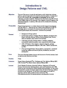
Example 1 – TV (1)
Fig. 1. Two ways of showing a TV viewer and its interfaces
Tian Zhang @ Nanjing University
21
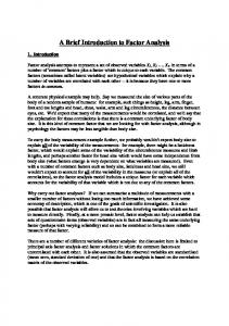
Example 1 – TV (2)
内部结构表示出一个类 如何在内部分解成两部 分以及哪些部分支持并 需要哪些不同接口。 该图说明了每一个TV 观众包含一个控制部分 和一个发生器部分。
Fig. 2. Internal view of a component (example suggested by Jim Rumbaugh) Tian Zhang @ Nanjing University
22
Example 1 – TV (3)
Fig. 3. A component with multiple ports
You can add ports to the external structure
ports allow you to group the required and provided interfaces to show logical interactions that a component has with the outside world
Tian Zhang @ Nanjing University
23
When to Use Composite Structures
Compare with Packages
packages are a compile-time grouping composite structures show runtime groupings
Natural fit for showing components and how they are broken into parts Much of this notation is used in component diagrams (Martin Flower).
Tian Zhang @ Nanjing University
24
Thirteen diagrams in UML 2.0
Structure Diagram
Class Diagram Composite Structure Diagram Component Diagram Deployment diagram Object Diagram Package Diagram
Behavior Diagram
Activity Diagram Use Case Diagram State Machine Diagram Communication Diagram Sequence Diagram Interaction Overview Diagram Timing Diagram Tian Zhang @ Nanjing University
25
Package Diagrams
A package is a grouping construct that allows you to take any construct in the UML and group its elements together into higher-level units Each package represents a namespace Use double colons to show package names in UML
System::Date Subsystem::Util::Date
Tian Zhang @ Nanjing University
26
Packages and Dependencies
Fig. 4. Package diagram for an enterprise application Tian Zhang @ Nanjing University
27
Implementing Packages
Fig. 5. A package implemented by other packages
It's quite common for an interface and its implementation to be in separate packages
Tian Zhang @ Nanjing University
28
Implementing Packages
This is an example of the pattern Separated Interface.
Fig. 6. Defining a required interface in a client package
Tian Zhang @ Nanjing University
29
Thirteen diagrams in UML 2.0
Structure Diagram
Class Diagram Composite Structure Diagram Component Diagram Deployment diagram Object Diagram Package Diagram
Behavior Diagram
Activity Diagram Use Case Diagram State Machine Diagram Communication Diagram Sequence Diagram Interaction Overview Diagram Timing Diagram Tian Zhang @ Nanjing University
30
Behavior Diagrams Part II: Behavior 11. Actions 12. Activities 13. Common Behaviors 14. Interactions 15. State Machines 16. Use Cases
(cite in Table of Contents)
Tian Zhang @ Nanjing University
31
The UML packages that support behavioral modeling, along with the structure packages they depend upon (CompositeStructures and Classes) are shown in the figure above.
Tian Zhang @ Nanjing University
32
Thirteen diagrams in UML 2.0
Structure Diagram
Class Diagram Composite Structure Diagram Component Diagram Deployment diagram Object Diagram Package Diagram
Behavior Diagram
Activity Diagram Use Case Diagram State Machine Diagram Communication Diagram Sequence Diagram Interaction Overview Diagram Timing Diagram Tian Zhang @ Nanjing University
33
Activity Diagrams
Activity diagrams are a technique to describe procedural logic, business process, and work flow. Activity diagrams play a role similar to flowcharts
the principal difference between them and flowchart notation is that they support parallel behavior
Activity diagrams have seen some of the biggest changes over the versions of the UML, so they have, not surprisingly, been significantly extended and altered again for UML 2
Tian Zhang @ Nanjing University
34
Activity Modeling
Activities are behaviors that emphasize the sequence and conditions for executing other behaviors.
The core constructs in an Activity include:
Secondary constructs show classifiers responsible for those behaviors. Nodes: Action, Object, Control, Parameter Edges: Control and Object Flows
Typical applications of Activities are process modeling in a wide variety of domains:
Computational Business Physical Systems Requirements
Tian Zhang @ Nanjing University
35
Action/Activity Integration
Eliminate overlapping semantics, create synergy. Data/control flow model of actions is replaced with the more general flow model of activities. Procedure replaced with Activity. Behavior invocation of Activities is replaced with the more general action model. InvocationNode replaced with Action. Composite actions become structured nodes, replace IterationGroups. Map/FilterAction replaced with ExpansionRegion, IteractionAction with LoopNode, ReduceAction removed. Activities define the flow graph (procedure), Actions define the nodes that perform behaviors. Collection actions folded into flow model.
Tian Zhang @ Nanjing University
36
Action/Activity Example update_account Amount Deposit
Account
+ Set Balance
Get Balance
Send Notice
Get Customer
Tian Zhang @ Nanjing University
37
Change Highlights
Queuing: Machine Part
Polish Part
Package Part
Tokens can
{stream}
stack up in “in/out” boxes backup in network prevent upstream behaviors from taking new inputs
Applicable to systems with significant resource constraints, such as physical or manual processes. Tian Zhang @ Nanjing University
38
Change Highlights
Parallelism in UML1 activities: B
C
A
Z Y
X
B
C
A
Z X
Trace:
Y
A, B||X, C||Y, Z
Tian Zhang @ Nanjing University
39
Change Highlights
Parallelism in UML2 activities: B
C
A
Z Y
X
B
C
A
Z X
Trace:
A,
Y
(B,C) || (X,Y)
,Z
Tian Zhang @ Nanjing University
40
Change Highlights
Unrestricted flow patterns in UML2 activities: N
B
A
C Z
X
Trace:
A,
Y
(B,C) , Z || (X,Y) || N
Tian Zhang @ Nanjing University
41
Decomposing an Action
Actions can be decomposed into subactivities
Tian Zhang @ Nanjing University
42
Tian Zhang @ Nanjing University
43
Partitions
If you want to show who does what, you can divide an activity diagram into partitions In UML 2, you can use a twodimensional grid
Tian Zhang @ Nanjing University
44
Signals
Actions can also respond to signals A time signal occurs because of the passage of time A signal indicates that the activity receives an event from an outside process As well as accepting signals, we can send them
Tian Zhang @ Nanjing University
45
Example – signal (1)
Tian Zhang @ Nanjing University
46
Example – signal (2)
Tian Zhang @ Nanjing University
47
Tokens
The initial node creates a token, which then passes to the next action, which executes and then passes the token to the next At a fork, one token comes in, and the fork produces a token on each of its outward flows on a join, as each inbound token arrives, nothing happens until all the tokens appear at the join then a token is produced on the outward flow
Tian Zhang @ Nanjing University
48
Flows and Edges
UML 2 uses the terms flow and edge synonymously to describe the connections between two actions
The simplest kind of edge is the simple arrow between two actions
Fig. Four ways of showing an edge Tian Zhang @ Nanjing University
49
Expansion Regions
An expansion region marks an activity diagram area where actions occur once for each item in a collection
Tian Zhang @ Nanjing University
50
Change Summary
Integration of actions and activities New core constructs added:
Pins (input/output, alternative sets) Groupings (structured nodes, interruptible regions)
UML 1.4 core constructs updated:
Edges (token flow) Object nodes (queuing, signals, parameters) Parameters (streaming, exceptions) Partitions (multidimensional, hierarchical, external) Control nodes (fork, join, decision, merge) Activities (attributes, operations, etc.)
Tian Zhang @ Nanjing University
51
When to Use Activity Diagrams
The great strength of activity diagrams lies in the fact that they support and encourage parallel behavior You can also use an activity diagram as a UMLcompliant flowchart In principle, you can take advantages of the forks and joins to describe parallel algorithms for concurrent programs It’s dangerous to use activity diagrams describing use cases, better off with the usual textual form
Tian Zhang @ Nanjing University
52
Thirteen diagrams in UML 2.0
Structure Diagram
Class Diagram Composite Structure Diagram Component Diagram Deployment diagram Object Diagram Package Diagram
Behavior Diagram
Activity Diagram Use Case Diagram State Machine Diagram Communication Diagram Sequence Diagram Interaction Overview Diagram Timing Diagram Tian Zhang @ Nanjing University
53
Variations in Sequence Diagrams
新的顺序图在描述复杂交互的伸缩能力方面有了显著提 高,新增了:
交互发生(Interaction occurrence),允许从一个交互引用到另一个 交互,避免了交互的复制; 组合片断(Combined fragment)和交互操作符等,以表示选择、循 环、并行、有序、引用等复杂的控制结构; 对生命线(Lifeline)的分解能力(Decomposition),可以通过实例的 内部结构来细化交互过程。
Tian Zhang @ Nanjing University
54
Loops, Conditionals, and the Like
These are new features in UML 2.0 The first thing to point out is that (M. Flower):
these aren't what sequence diagrams are good at to show control structures, better off with an activity diagram or indeed with code itself
Tian Zhang @ Nanjing University
55
Fig. 7. Interaction frames
Tian Zhang @ Nanjing University
56
Older Conventions in UML 1.x
UML 1.x used iteration markers and guards
An iteration marker is a * added to the message name. You can add some text in square brackets to indicate the basis of the iteration. Guards are a conditional expression placed in square brackets and indicate that the message is sent only if the guard is true. While these notations have been dropped from sequence diagrams in UML 2, they are still legal on communication diagrams.
Tian Zhang @ Nanjing University
57
Part decomposition
we see how ACSystem within UserAccess is to be ecomposed to AC_UserAccess, which is an Interaction owned by class ACSystem.
Fig. 8. Part Decomposition (example in Specification) Tian Zhang @ Nanjing University
58
Part Decomposition
To hide information, a lifeline can be subdivided into more detailed sequences
sd Decomposition
:Detector
create :Controller sd Overview
Insert(coin)
:User
ValidateCoin()
:VendingMachine ref Decomposition
RejectCoin() Insert(coin) RejectCoin()
Tian Zhang @ Nanjing University
59
Referencing Sequences
To avoid unnecessary duplication, it is possible to refer to already existing sequence diagrams
a way to quickly create new scenarios (e.g., tests and test suites)
sd BuyScenario
:User
:VendingMachine
ref
ChooseProduct Display(price) ref
ValidateCoin
Tian Zhang @ Nanjing University
60
Organizing Sequences
It is possible to organize sequence diagrams into flows to indicate how they fit together
sd Overview
Interaction Overview diagram = interaction diagram + activity diagram combine interactions in different ways to create new scenarios
Tian Zhang @ Nanjing University
ref
ref
[price=0]
ref
Initiate
ValidateCoin
[else]
DispenseProduct
61
Operator
Meaning
alt
Alternative multiple fragments; only the one whose condition is true will execute.
opt
Optional; the fragment executes only if the supplied condition is true. Equivalent to an alt with only one trace.
par
Parallel; each fragment is run in parallel.
loop
Loop; the fragment may execute multiple times, and the guard indicates the basis of iteration.
region
Critical region; the fragment can have only one thread executing it at once.
neg
Negative; the fragment shows an invalid interaction.
ref
Reference; refers to an interaction defined on another diagram. The frame is drawn to cover the lifelines involved in the interaction. You can define parameters and a return value.
sd
Sequence diagram; used to surround an entire sequence diagram, if you wish. Tab. 1. Common Operators for Interaction Frames Tian Zhang @ Nanjing University
62
Thirteen diagrams in UML 2.0
Structure Diagram
Class Diagram Composite Structure Diagram Component Diagram Deployment diagram Object Diagram Package Diagram
Behavior Diagram
Activity Diagram Use Case Diagram State Machine Diagram Communication Diagram Sequence Diagram Interaction Overview Diagram Timing Diagram Tian Zhang @ Nanjing University
63
Interaction Overview Diagrams
Interaction overview diagrams are a grafting together of activity diagrams and sequence diagrams
You can think of interaction overview diagrams as:
activity diagrams in which the activities are replaced by little sequence diagrams
or, a sequence diagram broken up with activity diagram notation used to show control flow.
Tian Zhang @ Nanjing University
64
Martin Fowler: “I'm not keen on them, as I think that they mix two styles that don't really mix that well. ”
Fig. 9. Interaction summary diagram Tian Zhang @ Nanjing University
65
Interaction Overview Diagram sd GoHomeSetup
Interaction with the syntax of Activity Diagram
ref
Authorization
Interaction Occurrence ref
FindLocation
sd
:ServiceUser
:ServiceBase SetHome
Expanded sequence diagram sd
:ServiceUser
:ServiceBase
SetInvocationTime SetTransportPreferences
Tian Zhang @ Nanjing University
66
Note That
Interaction Overview Diagrams focus on the overview of the flow of control The Lifelines and the Messages do not appear at this overview level
从概观的层次上不能有生命线和消息,但并不意味着在交互 (Interaction)片断内部不能出现 An Interaction diagram of any kind may appear inline as an ActivityInvocation
Tian Zhang @ Nanjing University
67
Thirteen diagrams in UML 2.0
Structure Diagram
Class Diagram Composite Structure Diagram Component Diagram Deployment diagram Object Diagram Package Diagram
Behavior Diagram
Activity Diagram Use Case Diagram State Machine Diagram Communication Diagram Sequence Diagram Interaction Overview Diagram Timing Diagram Tian Zhang @ Nanjing University
68
Communication Diagrams
Definition in Specification
Communication Diagrams focus on the interaction between Lifelines where the architecture of the internal structure and how this corresponds with the message passing is central. Communication Diagrams correspond to simple Sequence Diagrams that use none of the structuring mechanisms such as InteractionUses and CombinedFragments. It is also assumed that message overtaking (i.e., the order of the receptions are different from the order of sending of a given set of messages) will not take place or is irrelevant. 通信图着重体现的是交互者之间的交互关系
Tian Zhang @ Nanjing University
69
messages m1 and m3 being sent concurrently from :r towards two instances of the part s sequence numbers show how the other messages are sequenced
Tian Zhang @ Nanjing University
70
When to Use Communication Diagrams
sequence diagrams are better when you want to emphasize the sequence of calls communication diagrams are better when you want to emphasize the links however, a strong part of the decision is personal preference
Tian Zhang @ Nanjing University
71
Thirteen diagrams in UML 2.0
Structure Diagram
Class Diagram Composite Structure Diagram Component Diagram Deployment diagram Object Diagram Package Diagram
Behavior Diagram
Activity Diagram Use Case Diagram State Machine Diagram Communication Diagram Sequence Diagram Interaction Overview Diagram Timing Diagram Tian Zhang @ Nanjing University
72
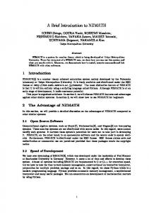
Timing Diagram
Used to show interactions when a primary purpose of the diagram is to reason about time. Focus on conditions changing within and among Lifelines along a linear time axis.
Tian Zhang @ Nanjing University
73
A Lifeline for a discrete object State or condition
Duration constraint
Lifeline
sd UserAcc_User {d..3*d}
:User
WaitAccess time constraint
WaitCard
CardOut
Idle
Code
0 tick mark values
1
OK {t..t+3}
2
t event or stimulus
Tian Zhang @ Nanjing University
timing ruler
74
Lifeline (from BasicInteractions, Fragments)
Description
Semantics
A lifeline represents an individual participant in the Interaction. While Parts and StructuralFeatures may have multiplicity greater than 1, Lifelines represent only one interacting entity. The order of OccurrenceSpecifications along a Lifeline is significant denoting the order in which they will occur. The semantics of the Lifeline (within an Interaction) is the semantics of the Interaction selecting only OccurrenceSpecifications of this Lifeline.
Lifelines are basically the same concept as before in UML 1.x.
Tian Zhang @ Nanjing University
75
OccurrenceSpecification
Description
An OccurrenceSpecification is the basic semantic unit of Interactions. The sequences of occurrences specified by them are the meanings of Interactions. OccurrenceSpecifications are ordered along a Lifeline.
Semantics
The semantics of an OccurrenceSpecification is just the trace of that single OccurrenceSpecification. The understanding and deeper meaning of the OccurrenceSpecification is dependent upon the associated Message and the information that it conveys.
Tian Zhang @ Nanjing University
76
Compact Lifeline with States Lifeline
State or condition
Duration constraint
Sometimes it is more economical and compact to show the state or condition on the vertical Lifeline
Tian Zhang @ Nanjing University
77
Timing Diagram with more than one Lifeline and with Messages Duration Constraints State or condition
Lifelines Time Constraint
Message
Duration Observation
Time Observation Tian Zhang @ Nanjing University
78
Graphic nodes and paths included in timing diagrams Node Type
Notation
Reference
State or condition timeline
This is the state of the classifier or attribute, or some testable condition, such as an discrete enumerable value. It is also permissible to let the statedimension be continuous as well as discrete.
General value lifeline
Shows the value of the connectable element as a function of time. Value is explicitly denoted as text. Crossing reflects the event where the value changed.
Lifeline
see “lifeline” page
Tian Zhang @ Nanjing University
79
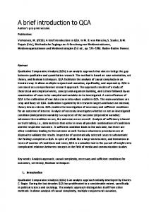
Simple scenario - coffee pot
Rules of time :
Pump –
向壶中注水
at least 10 seconds must pass between the pump coming on and the hotplate coming on when the water reservoir becomes empty, the pump switches off, and the hotplate cannot stay on for more than 15 minutes more
Hotplate –
给咖啡壶加热
Tian Zhang @ Nanjing University
80
Fig. Timing diagram showing states as lines
State or condition timeline 以水平中轴为基准,将两个对象的时间图放到一起。这种复合的方式 可以扩展到多个,但时间轴需要统一。 Tian Zhang @ Nanjing University
81
Fig. Timing diagram showing states as areas
Shows the value of the connectable element as a function of time. Value is explicitly denoted as text. Crossing reflects the event where the value changed.
Tian Zhang @ Nanjing University
82
Useful UML Web Sites
UML home page, at www.uml.org UML Forum, at www.uml-forum.com The leading group, called U2P (UML 2.0 Partners), at www.u2-partners.org One of the proposing groups, the communityUML. See http://community-ml.org/submissions.htm A specific Web site for the 2U Consortium can be found at www.2uworks.org A specific Web site for the precise UML group (pUML) can be found at www.cs.york.ac.uk/puml/uml2_0.html
Tian Zhang @ Nanjing University
83
Thanks !
Tian Zhang @ Nanjing University
84
Appendix 1
UML 2.0 RFI: 修订信息需求 UML 2.0 RFP: 提案需求 UML 2.0 Task Force: 工作组 Object and Reference Model Subcommittee (ORMSC): 对象和参考模型小组委员会
Tian Zhang @ Nanjing University
85
Appendix 2 OMG's Technology Adoption Process
1. 2. 3. 4. 5. 6.
optional RFI stage TF issues RFP, evaluates submissions voting to Adopt an OMG specification finalization - getting ready for prime time the OMG specification maintenance Cycle retiring Obsolete Specifications
Tian Zhang @ Nanjing University
86
Martin Flower
Patterns of Enterprise Application Architecture Refactoring: Improving the Design of Existing Code UML Distilled: A Brief Guide to the Standard Object Modeling Language Planning Extreme Programming Analysis Patterns: Reusable Object Models
Tian Zhang @ Nanjing University
87
Concepts in UML 2.0 Behavior Part
Actions Activities Interactions State Machines Use Cases
Tian Zhang @ Nanjing University
88
Actions
An action is the fundamental unit of behavior specification An action takes a set of inputs and converts them into a set of outputs
either or both sets may be empty the activity flow model supports providing inputs to actions from the outputs of other actions
Some of the actions modify the state of the system in which the action executes
Tian Zhang @ Nanjing University
89
Actions (2)
Basic actions include those that perform operation calls, signal sends, and direct behavior invocation primitive actions are defined so that they either carry out a computation or access object memory, but never both
Tian Zhang @ Nanjing University
90
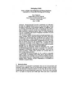
MSC-2000
UML 2.0
Comments
MSC (Message Sequence Chart)
Interaction diagrams
The individual scenarios. MSC and UML have different approaches to language.
Event
EventOccurrence
Instance
Lifeline
Notice that a lifeline refers to a property (part) of a composite structure, while the instance is a part of a structure
Message
Message
Both distinguish between asynchronous and synchronizing messages
Method call
Operation call
Action
ExecutionOccurrence
Gate
Gate
In UML we have only message gates, while in MSC there are also general ordering gates.
No direct counterpart
Interaction fragment
See Interaction fragment
Coregion
Coregion
In MSC this is a basic concept from 1992, but in UML 2.0 this is only presented as a shorthand for the par-operator. No semantic difference
Decomposition
PartDecomposition
How the aggregate hierarchy of the structure is reflected in interactions/MSCs.
MSC reference
Interaction Occurrence
The ability to refer to another interaction. See also Referring another interaction / MSC diagram 91
Tian Zhang @ Nanjing University