Tao Xu and Krishnendu Chakrabarty ... B.2.2 B.2.m [Hardware]: Performance analysis and design aids, ... plugged into a controller circuit board that can be programmed and ... synthesis methods are adapted for the automated design of biochips. .... easily mapped to the clique-partitioning problem from graph theory. [15].
10.4
Broadcast Electrode-Addressing for Pin-Constrained Multi-Functional Digital Microfluidic Biochips Tao Xu and Krishnendu Chakrabarty Department of Electrical and Computer Engineering Duke University, Durham, NC 27708, USA {tx, krish}@ee.duke.edu
Abstract Recent advances in digital microfluidics have enabled lab-on-a-chip devices for DNA sequencing, immunoassays, clinical chemistry, and protein crystallization. Basic operations such as droplet dispensing, mixing, dilution, localized heating, and incubation can be carried out using a two-dimensional array of electrodes and nanoliter volumes of liquid. The number of independent input pins used to control the electrodes in such microfluidic “biochips” is an important cost-driver, especially for disposable PCB devices that are being developed for clinical and point-of-care diagnostics. However, most prior work on biochip design-automation has assumed independent control of the electrodes using a large number of input pins. Another limitation of prior work is that the mapping of control pins to electrodes is only applicable for a specific bioassay. We present a broadcast-addressing-based design technique for pin-constrained multi-functional biochips. The proposed method provides high throughput for bioassays and it reduces the number of control pins by identifying and connecting control pins with “compatible” actuation sequences. The proposed method is evaluated using a multifunctional chip designed to execute a set of multiplexed bioassays, the polymerase chain reaction, and a protein dilution assay.
Categories and Subject Descriptors B.2.2 B.2.m [Hardware]: Performance analysis and design aids, miscellaneous.
General Terms Algorithms, Performance, Design.
Keywords Droplet-based microfluidics, electrowetting-on-dielectric, lab-onchip.
1. INTRODUCTION The emergence of microfluidic biochips has led to the automation of laboratory procedures in biochemistry and the miniaturization of laboratory instruments [1,2]. Compared to traditional bench-top procedures, microfluidic biochips offer the advantages of low sample and reagent consumption, less likelihood of error due to minimal human intervention, high throughput, and high sensitivity. These lab-on-a-chip devices are now being advocated for a wide range of applications such as high-throughput DNA sequencing, immunoassays and clinical chemistry, environmental toxicity monitoring and the detection of airborne chemicals, detection of explosives such as TNT, and point-of-care diagnosis of diseases [3]. Currently, most commercially-available biochips rely on either continuous fluid flow in etched microchannels or microarrays [2]. _________________________________________ *This work was supported in part by the National Science Foundation under grant CCF-0541055. Permission to make digital or hard copies of all or part of this work for personal or classroom use is granted without fee provided that copies are not made or distributed for profit or commercial advantage and that copies bear this notice and the full citation on the first page. To copy otherwise, or republish, to post on servers or to redistribute to lists, requires prior specific permission and/or a fee. DAC 2008, June 8–13, 2008, Anaheim, California, USA Copyright 2008 ACM 978-1-60558-115-6/08/0006…5.00
173
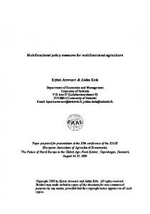
An alternative category of microfluidic biochips relies on the principle of electrowetting-on-dielectric. Discrete droplets of nanoliter volumes can be manipulated in a “digital” manner on a two-dimensional electrode array. Hence this technology is referred to as “digital microfluidics” [1]. A t ypi cal digital micr ofluidi c biochip consists of a two-dimensional electrode array [1]. A unit cell in the array includes a pair of electrodes that acts as two parallel plates. The bottom plate contains a patterned array of electrodes, and the top plate is coated with a continuous ground electrode. A droplet rests on a hydrophobic surface over an electrode, as shown in Fig. 1. It is moved by applying a control voltage to an electrode adjacent to the droplet and, at the same time, deactivating the electrode just under the droplet. This electronic method of wettability control creates interfacial tension gradients that move the droplets to the charged electrode. Using the electrowetting phenomenon, droplets can be moved to any location on a two-dimensional array. By varying the patterns of control-voltage activation, many fluid-handling operations such as droplet dispensing, merging, splitting, mixing, localized heating, and incubation can be executed on-chip in a programmable fashion. For example, mixing can be performed by routing two droplets to the same location and then turning them about some pivot points [4]. Electrodes are connected to control pins for electrical actuation. A number of prototype biochips use a direct-addressing scheme for the control of electrodes [5]. Each electrode is connected to a dedicated control pin; it can therefore be activated independently. This method allows the maximum freedom of droplet manipulation, but it necessitates an excessive number of control pins for practical biochips. As more bioassays are concurrently executed on digital microfluidic platforms [7], system complexity and the number of electrodes is expected to increase steadily. Recently, a droplet-based biochip that embeds more than 600,000 20 µm by 20 µm electrodes, and uses dielectrophoresis for droplet manipulation and control, has been demonstrated [9]. The large number of control pins and the associated interconnect-routing problem significantly adds to product cost. To address the need for low-cost, PCB technology has been proposed to inexpensively mass-fabricate digital microfluidic biochips [8]. This inexpensive manufacturing technique allow us to build disposable PCB-based microfluidic biochips that can be easily plugged into a controller circuit board that can be programmed and powered via a standard USB port. However, a large number of independent control pins necessitates multiple PCB layers, which adds significantly to the product cost. Thus, the design of pin-constrained digital microfluidic arrays is of great practical importance for the emerging marketplace. Of particular interest are design techniques that provide high throughput despite the availability of only a limited number of control pins. While individual electrodes can be addressed using a serial-to-parallel interface, such a method is impractical for a low-cost PCB platform because it requires active elements (gates, flip-flops, etc.). Electrode-addressing methods that allow the control of microfluidic arrays with a small number of pins are now receiving attention. The method presented in [9] uses array partitioning and careful pin-assignment to reduce the number of control pins.
Ground electrode
Top glass plate Droplet
Hydrophobic layer
Filler Fluid
F
0
1
0
E1
E2
E3
E4
Fig. 2: Illustration of a “don’t-care” in electrode activation. Bottom plate
Control electrodes
E2
E1
(a) (b) Fig. 1: A digital microfluidic array: (a) 2-D electrode array (b) unit cell side view. However, this method is specific to a target biofluidic application. an alternative design uses row- and column-addressing, a technique referred to as “cross referencing” [10]. An electrode is connected to two pins, corresponding to a row and a column, respectively. In this paper, we present a broadcast-addressing-based design technique for pin-constrained and multi-functional biochips. The proposed method provides high throughput for bioassays and it reduces the number of control pins by identifying and connecting control pins with “compatible” actuation sequences. We evaluate the proposed method using a multifunctional chip designed to execute a set of multiplexed bioassays, the polymerase chain reaction, and a protein dilution assay. The organization of the rest of the paper is as follows. In Section 2, we discuss related prior work on biochip design-automation and pin-constrained chip design. Section 3 describes the proposed broadcast-addressing-based pin-constrained design method. Section 4 evaluates the proposed method using a biochip for multiplexed bioassays, and a multifunctional biochip used for several target assays. Conclusions are drawn in Section 5.
2. RELATED PRIOR WORK Research on design-automation techniques for microfluidic biochips has gained momentum in recent years, in part due to the enthusiasm generated from advances in digital microfluidic technology. In [5], classical architectural- and geometric-level synthesis methods are adapted for the automated design of biochips. A unified synthesis method, which combines scheduling, resource binding, and module placement, has been proposed in [5]. Systematic droplet routing strategies have also been developed [11,12]. These early design automation techniques are useful for biochip design and rapid prototyping, but they all rely on the availability of a direct-addressing scheme [13]. However, as discussed in Section 1, direct-addressing suffers from the drawback of higher wiring complexity. Pin-constrained design for digital microfluidics was addressed in [9].This method uses array partitioning and careful pin-assignment to reduce the number of control pins. However, it requires detailed information about the scheduling of assay operations, microfluidic module placement, and droplet routing pathways. Thus, the array design in such cases is specific to a target biofluidic application. In another method proposed in [6], the number of control pins for a fabricated electrowetting-based biochip is minimized by using a multi-phase bus for the fluidic pathways. Every nth electrode in an n-phase bus is electrically connected, where n is small number (typically n = 4). Thus, only n control pins are needed for a transport bus, irrespective of the number of electrodes that it contains. Although the multi-phase bus method is useful for reducing the number of control pins, it is only applicable to a one-dimensional (linear) array. An alternative method based on a cross-reference driving scheme is presented in [10]. This method allows control of an N×M grid
174
E3
E8
E4
E7
E6
E5
(a) Electrode Activation Sequence
1 0 1 0 0 X X X X
2 1 0 0 X X X X 0
3 0 0 X X X X 0 1
4 0 X X X X 0 1 0
5 X X X X 0 1 0 0
6 X X X 0 1 0 0 X
7 X X 0 1 0 0 X X
8 X 0 1 0 0 X X X
(b) Fig. 3: Example of activation sequence calculation (a) routing and layout information (b) calculated activation sequences. array with only N+M control pins. The electrode rows are patterned on both the top and bottom plates, and placed orthogonally. An electrode is activated by highlighting the column and row pins it resides on. However, due to electrode interference, this design cannot handle the simultaneous movement of more than two droplets. The resulting serialization of droplet movement is a serious drawback for high-throughput applications such as DNA sequencing, air-quality monitoring, and multiplexed immunoassays. Higher throughput can be achieved for such arrays using a graph-theoretic optimization technique [14]. However, this design requires a special electrode structure (i.e., both top and bottom plates contain electrode rows), which results in increased manufacturing cost.
3. BROADCAST ADDRESSING In this section, we propose an alternative pin-constrained design method that can be used for multifunctional biochips.
3.1 “Don’t-Cares” in Electrode-Actuation Sequences To execute a specific bioassay, droplet routes and the schedule of operations are programmed into a microcontroller to drive the electrodes. Routing and scheduling information is stored in the form of (ternary) electrode activation sequences, where each bit representing the status of the electrode at a specific time-step. The status can be either “1” (activate), “0” (deactivate) or “F” (floating). A floating signal is provided input to an electrode when it is required to be neither active nor inactive, as shown in Fig. 2. At time spot t, a droplet is to be held at electrode E3. This electrode needs to be at high voltage (“1”), and the two adjacent electrodes E2 and E4 need to be deactivated (“0”). E1 is not involved in this holding step, therefore a floating value can be assumed for it. Since the voltage on E1 has no impact on the droplet operations for this step, E1 can also be assigned “1” or “0”. Here we represent this status using the symbol “x” and refer to it as “don’t-care”. This concept is similar to the don’t-cares that arise in logic synthesis during integrated circuit design. We use the three values “1”, “0”, and “x” to represent the electrode-activation sequences for a bioassay. An example is shown
1
2
4
8 7
3
6
5
Fig. 4: Mapping of the activation sequences of Fig. 3 to an undirected graph. in Fig. 3. A droplet is routed anticlockwise, one electrode per step, along the loop consisting of 8 electrodes. Suppose that at time instant (clock cycle) t0, the droplet rests on electrode E2. The activation sequence for each electrode is now calculated and listed in Fig. 3(b). In Fig. 3(b), each sequence contains several don’t-care terms, which can be replaced by “1” or “0”. By careful replacing these don’t-care terms, the two activation sequences corresponding to E1, E4 can be made identical. For example, we can map the four don’t-cares in activation sequence for E1 with “0010” and map the four don’t-cares in activation sequence for E4 with “0100”. We refer to such sequences as compatible sequences. Compatible sequences can be generated from a single signal source. Therefore, the corresponding electrodes E1 and E4 can be connected to a single control pin.
3.2. Optimization Based on Clique Partitioning in Graphs In this subsection, we focus on reducing the number of control pins by connecting together electrodes with mutually-compatible activation sequences, and addressing them using a single control pin. Therefore, the resulting electrode-access method is referred to as a broadcast addressing. We first partition the electrodes into groups. For all the electrodes in any group, the corresponding activation sequences must be pairwise-compatible. Our goal is to find an optimal partition that leads to the minimum number of groups, which in turn yields the minimum number of control pins. The problem of finding the minimum number of groups can be easily mapped to the clique-partitioning problem from graph theory [15]. We use the example in Fig. 3 to illustrate this mapping. Based on the activation-sequence table, an undirected graph, referred to as electrode-activation graph, is constructed; see Fig. 4. Each node in the graph represents an activation sequence for an electrode. An edge in the graph between a pair of nodes indicates that their corresponding activation sequences are compatible. For example, nodes 1 and 4, which represent the activation sequences for electrode E1 and E4, respectively, are connected by an edge because the activation sequences can be converted to a single sequence “01000010” by replacing the don’t-care terms. A clique in a graph is defined as a complete subgraph, i.e., any two nodes in this subgraph are connected by an edge [15]. Clique partitioning refers to the problem of dividing the set of nodes into non-overlapping subsets such that the subgraph induced by each subset of nodes is a clique. A minimal clique partition is one that covers the nodes in the graph with a minimum number of non-overlapping cliques. The grouping of droplets as discussed above is equivalent to the clique-partitioning problem. A minimal clique partition here for this example is given by {1,4}, {5,8}, {2,6}, {3,7}. Even though the general clique partitioning problem is known to be NP-hard [15], a number of heuristics are available in the literature to solve it in an efficient manner. After an efficient partitioning of electrodes is derived, we address all the electrodes in a group using a single control pin. A common activation sequence compatible to all the individual sequences in each group is calculated and used as the input sequence for the control pin. In the above example, electrodes E1, E4 are connected
175
and they share the common activation sequence of {01000010}. Since we broadcast a common activation sequence to several electrodes, we refer to this addressing method as “broadcast addressing”. The complete steps in broadcast addressing are as follows: 1. Obtain droplet-routing information from the biochip synthesis results and calculate the control-signal sequence for each control pin. The control-signal sequence consists of the values 1 (activated), 0 (deactivated), and x (don’t-care). 2. Draw an undirected graph representing the relationship between control-signal sequences. For every pair of electrode-activation sequence, if one sequence can be derived from the other by simply changing x’s to 1’s/0’s, then draw an edge between the nodes representing them. 3. Apply clique partitioning to minimize the number of independent control signals. 4. Group and connect the control lines that are in the same clique. The general clique partitioning problem is known to be NP-hard [15]. Therefore, we use a heuristic based on the union-find algorithm [16], which partitions the graph by iteratively searching for a maximal clique, defined as a clique not contained in any larger clique, and then deleting the maximal clique from the graph. The algorithm takes O(N3) computation time, where N is the number of electrodes on the chip. By using this broadcast-addressing method, the input bandwidth for the microfluidic biochip can be significantly reduced. For the example in Fig. 3, instead of using eight independent control pins to address the electrode loop, broadcast addressing only needs four control pins. A more significant reduction is expected in large arrays with more don’t-care terms in activation sequences. Another advantage of the broadcast-addressing method is that it provides maximum freedom of droplet movement. It does not change the schedule of operations or the droplet-routing pathways for the target bioassay; therefore, bioassays can be executed as fast as on a direct-addressing-based chip. Compared to the array-partitioning-based method [9], broadcast addressing does not need to limit the number of concurrent droplet movements to get fewer partitions. The proposed method also reduces assay operation time compared to cross-referencing [10]; the latter typically requires several sub-steps for a set of droplet manipulations that can be carried out concurrently in a direct-addressing-based chip. These advantages are quantitatively evaluated using a real chip example in Section 4.
3.3 Broadcast Addressing for Multifunctional Biochips Broadcast addressing can also be applied to multifunctional biochips, i.e., biochips targeting the execution of a set of (multiple) predetermined bioassays. For each target bioassay, droplet routing and schedule information are collected and activation sequences are calculated. Next, for each electrode, we merge the activation sequences from the different assays and obtain a collective activation sequence. Note that the compatibility of activation sequences is independent of the ordering of the sequences. Therefore, the merging of activation sequences can be carried out in any arbitrarily-chosen order. Once the collective activation sequences are derived, the same steps as described in Section 4.1 are carried out to derive the electrode partitions and the wiring (connection of input pins to electrodes) plan. Note that the longer the activation sequences, the more specified entries, i.e., “1” and “0” exist, and the less compatibility we observe. Therefore, multi-functionality may necessitate a larger number of input control pins for the proposed broadcast addressing method. This trade-off is evaluated in the next section.
Table 1: A fragment of the activation sequences for multiplexed assay.
Nop
S1
…
…
…
…
…
…
…
x
x
x
0
1
0
x
x
x
0
…
1
0
x
x
x
0
1
0
x
x
x
…
9
x
0
1
0
x
x
x
0
1
0
x
x
…
10
x
x
x
x
x
x
x
x
x
x
x
x
…
12
x
x
x
x
x
x
x
x
x
x
x
x
…
13
x
0
1
0
x
x
x
0
1
0
x
x
…
14
0
1
0
x
x
x
0
1
0
x
x
x
…
15
1
0
x
x
x
0
1
0
x
x
x
0
…
16
x
x
0
1
0
x
x
x
0
1
0
x
…
…
…
…
…
…
…
…
…
Sample 2
Sample 1
0
0
…
Detection site 2
…
Detection site 1
1
8
…
Fig. 5: Sequencing graph model for a multiplexed bioassay. S1, S2 are samples, R1, R2 are reagents, M1 ~M4 are mixing operations, and D1 ~D4 are detection operations.
…
D4
7
…
D3
…
M4
M3
D2
I8
…
D1
I7
Activation Sequences(0s ~ 13s) …
M2
M1
I6
Electrode # (7~20)
R2
…
I5
R1
…
I4
R2
…
I3
R1
…
I2
S2
…
I1
S1
S2
4
Test stimuli droplet
3×3-array mixer
3 14
5 7
2
10
12
5
14
7
7
6
6
14
7
7
8
13
6
14
24
Droplet source
Droplet sink
25 3 22
3
5
1 1
13
14 3
24 15 17 18 20
21 19 9 10 11
Reagent 2
Reagent 1
Fig. 6: Mapping of a multiplexed bioassays to a 15×15 array. Mixing operation
0
Pre-mixing transportation
4
M2 D1
40
D2
M4 50
12 11 16 2
23
21
5
5
M1
M3
9
14 3
Fig. 8: Broadcast addressing for the multiplexed assay chip.
Bioassay completion time (s)
30
8
Detection operation
10 20
3 14
3
4
D3
60
D4
70
Fig. 7: Schedule result for the multiplex bioassay.
4. EXPERIMENTAL RESULTS
120 100 80
4.1 Multiplexed Assay We first map a recently demonstrated multiplexed biochemical assay, which consists of a glucose assay and a lactate assay based on colorimetric enzymatic reactions, on to the array. Fig. 5 shows the flowchart for the multiplexed assays in the form of a sequencing graph [5]. For each sample or reagent, two droplets are dispensed into the array. Four pairs of droplets, i.e., {S1, R1}, {S1, R2}, {S2, R1}, {S2, R2}, are routed together in sequence for the mixing operation. Mixed droplets are finally routed to the detection site for analysis. In [6], the multiplexed bioassays were mapped to a digital
176
Broadcast Defect occurence probability p Array-partitioningaddressing based method method
60 40 20 0
In this section, we evaluate the proposed broadcast addressing method by using it to pin-constrained design of biochips for a multiplexed immunoassay, a representative protein assay, and the polymerase chain reaction (PCR) procedure. Each assay is first mapped to a 15×15 electrode array controlled using the direct-addressing scheme. Next, the proposed broadcast-addressing method is used to reduce the number of control pins.
Cross-referencingbased method
140
1
2
3
Fig. 9: Comparison of assay completion times.
microfluidic platform containing a 15×15 array, as shown in Fig. 6. A depiction of the droplet pathways for multiplexed glucose and lactase assays is given in Fig. 6. In the multiplexed assay, eight droplets (two droplets from each sample/reagent) are dispensed and routed to the mixer located at the center. Next, four mixing and detection operations are carried out in a pipeline manner following the schedule shown in Fig. 7. We assume that the droplets are transported at the rate of 1 electrode/second, i.e., 1 Hz. Next we apply the proposed broadcast-addressing method to the above chip layout. As shown in Fig. 6, the multiplexed-assay chip utilizes 59 electrodes. We calculate the electrode activation sequences based on the scheduling and routing result presented in Section 4.1. A fragment of the activation sequences is listed in Table 1. Next, the clique-partitioning-based broadcast addressing method is used to generate the electrode connections and the pin-assignment plan. The results are shown in Fig. 8. The pins assigned to the electrodes are shown in the corresponding boxes.
In Fig. 8, the number of control pins is reduced from 59 to 25, almost a 60% reduction compared to direct-addressing method. Due to considerable reduction in wiring complexity, fabrication cost is reduced significantly. There is no increase in the assay time compared to a direct-addressing chip that uses 59 electrodes. The cross-reference-based method in [14] also leads to a significant reduction in number of control pins, but at the expense of higher assay completion times. The results are shown in Fig. 9. With broadcast addressing, we obtain an assay completion time of 73 s. The cross-referencing-based method requires the 30 control pins but a longer completion time of 132 s. The array-partitioning-based method in [9] leads to a completion time of 73 s. However it requires 35 control pins, i.e., an increase of 40% compare to the broadcast-addressing method. Tris-HCL (pH 8.3) KCL
Bovine serum albumin Gelatin
Mix
Mix
Beosynucleotide AmpliTag DNA Primer triphoshate LamdaDNA
Mix
Mix
Assuming a direct-addressing scheme, the layout in Fig. 11 requires 62 control pins. However, using the proposed broadcastaddressing method, we reduce the number of control pins to 14. The pin-constrained layout for the PCR chip is shown in Fig. 13.
4.3 Protein Dilution The third assay that we consider consists of the dilution steps in a real-life protein assay. The feasibility of performing a colorimetric protein assay on a digital microfluidic biochip has been successfully demonstrated [5]. Based on the Bradford reaction [5], the protocol for a generic droplet-based colorimetric protein assay is as follows. First, a droplet of the sample, such as serum or some other physiological fluid containing protein, is generated and dispensed into the biochip. Buffer droplets, such as 1M NaOH solution, are then introduced to dilute the sample to obtain a desired dilution factor (DF). This on-chip dilution is performed using multiple hierarchies of binary mixing/splitting phases, referred to as the interpolating serial dilution method [1]. The mixing of a sample 1 2
Mix
Mix
1
2
3
3
3
7
5
7
14
Mix
8
9 3 12
1
6
14
1
4
11 14
6
8
Tris-HCL (pH 8.3)
Lamda DNA
1
2
5
1
13 9
5
6
12
KCL
1
12 7
6
Fig. 10: Sequencing graph for the mixing stage of PCR.
2
14 7 11
9
13 10
6
13
7
11
6
2
2
4
11
13
6
8
3
3
3
2 1
2 1
AmpliTag DNA
Fig. 13: Broadcast addressing for the PCR chip.
Bovine serum albumin
Gelatin
Beos ynucleotide triphosaphate Primer
Fig. 11: Mapping of the PCR assay on a 15×15 array. 0
2 4 6
M1 M2
8
10 12 14
M5
M4
M6
Fig. 14: Sequencing graph for the protein assay.
M3
Mixer/diluter/storage
16 18
M7
20
Sample solution
Fig. 12: Schedule for the PCR assay.
4.2 Polymerase Chain Reaction (PCR) For the second assay, we use the mixing stages of the PCR. These stages are used for rapid enzymatic amplification of specific DNA strands. Recently, the feasibility of performing droplet-based PCR on digital microfluidics-based biochips has been successfully demonstrated [11]. Its assay protocol can be modeled by a sequencing graph, as shown in Fig. 10. Mapping the protocol on to the array, we obtain the chip layout and schedule shown in Fig. 11 and Fig. 12, respectively.
177
Buffer
Mixer/diluter/storage
Fig. 15: Layout for protein-dilution chip.
multi-functional biochip design. Here we design a multi-functional biochip that can execute all the three assays described in the previous subsections. The pin-assignment for the multi-functional chip can be obtained by combining the chip layouts for the three different assays, see Fig 18. Note that only 81 electrodes on the 15×15 array are used in this layout and thereby need to be addressed. Next we consider the addressing problem for the multi-functional chip. The activation sequences for the PCR assay and protein assay are determined and combined with that from the multiplexed assay. The broadcast addressing method is carried out and it generates a chip layout with only 37 control pins. The addition of two assays to the biochip for the multiplexed assay, and 22 (81–59 = 22) new electrodes, leads to only 13 extra control pins. These results highlight the scalability attribute of the proposed design method.
0 Dlt1 10 20
Dlt10
30 40
Dlt3
Dlt2
Dlt1
Dlt12
Dlt11
Dlt2
Dlt3
Dlt5
Dlt4
Dlt13 Dlt7
Dlt6
50 Dlt9
Dlt13
Dlt12
Dlt16
Dlt15
Dlt14 ...
...
...
...
...
...
...
130
Dlt11
Dlt10
Dlt8
Mix1
Mix2
Mix3
Mix4
Mix5
Mix6
Mix7
Mix8
Opt1
Opt2
Opt3
Opt4
Opt5
Opt6
Opt7
Opt8
140 150
5. CONCLUSIONS
Fig. 16: Schedule for the protein dilution assay, Dlt –dilution, Mix – mixing, Opt – optical detection.
We have described a broadcast-based electrode-addressing method for pin-constrained digital microfluidic biochips. We have shown how compatible electrodes are identified and connected. This procedure leads to a considerable reduction in the number of control pins. We have used the proposed method to solve the electrode addressing problem for a multi-functional biochip and achieved a significant reduction in the input-control bandwidth required for a set of bioassays. Compared to previously published array-partitioning and cross-referencing methods, broadcast addressing method allows us to achieve a significantly higher level of concurrency in droplet manipulation operations, leading to higher throughput for bioassays.
3 6
1
8
4
7
11
6
12
7
3 15 18 26 14
24
7
25 12 13 14 8
16 7
17
13 9
4
9
4 18
20 7 26 11 13 27 24 23 21 22 19 9
4
23
16
2
11
10
1
3
7
5
2
REFERENCES Fig. 17: Broadcast-addressing for the protein-dilution chip. 18 12 24 7 22 5 24 8 12 5 36 35 24 1 17 24 10 26 19
11 23 15
15 14
5 22 8
13
9 9 22 8
24 5
5 13 21 21 22 8 10
3
6
25 33 34 27 28 23 21 37 13 8
27 12 11 23 24 13 18 37 15 23 28 19 17 18
24 8
23
16
4
8
10
7
14
5
8 24
2 4
Fig. 18: Pin-assignment layout for multi-functional chip. droplet of protein concentration C and a unit buffer droplet results in a droplet with twice the unit volume, and concentration C/2. Splitting this large droplet results in two unit-volume droplets of concentration C/2 each. Continuing this step in a recursive manner using diluted droplets as samples, an exponential dilution factor of DF = 2N can be obtained in N steps. After dilution, droplets of reagents, such as Coomassie brilliant blue G-250 dye, are dispensed into the chip, and they mix with the diluted sample droplets. Next the mixed droplet is transported to a transparent electrode, where an optical detector (e.g., a LED-photodiode setup) is integrated. The protein concentration can be measured from the absorbance of the products of this colorimetric reaction using a rate kinetic method. We map the protein assay to the 15×15 array. Fig. 15 shows the chip layout and Fig. 16 illustrates the schedule for this protocol. In Fig. 15, 52 electrodes are used in the chip layout. This number is reduced to only 27 after the broadcast-addressing method is applied; see Fig. 17.
4.4 Broadcast-Addressing for a Multi-functional Chip Finally, we evaluate the performance of the proposed method for
178
[1] Fair, R. B. et al., “Electrowetting-based on-chip sample processing for integrated microfluidics”, Proc. IEDM, pp. 32.5.1-32.5.4, 2003. [2] Verpoorte, E. and De Rooij, N. F., “Microfluidics meets MEMS”, Proc. IEEE, vol. 91, pp. 930-953, 2003. [3] Fair, R. B. et al., “Chemical and biological applications of digital-microfluidic devices”. Proc. IEEE Design & Test of Computers, vol. 24, pp. 10-24, 2007. [4] Paik, P. Y. et al., “Rapid droplet mixers for digital microfluidic systems”, Lab on a Chip, vol. 3, pp. 253-259, 2003. [5] Chakrabarty, K. and Su, F., “Digital Microfluidic Biochips: Synthesis, Testing, and Reconfiguration Techniques”, CRC Press, FL, 2006. [6] Srinivasan, V. et al., “An integrated digital microfluidic lab-on-a-chip for clinical diagnostics on human physiological fluids”, Lab on a Chip, vol. 4, pp. 310-315, 2004. [7] Silicon Biosystems, http://www.siliconbiosystems.com [8] Advanced Liquid Logic, Inc., http://www.liquid-logic.com [9] Xu, T. and Chakrabarty, K., “Droplet-trace-based array partitioning and a pin assignment algorithm for the automated design of digital microfluidic biochips”, Proc. IEEE/ACM CODES+ISSS, pp. 112-117, 2006. [10] Fan, S. K. et al., “Manipulation of multiple droplets on N×M grid by cross-reference EWOD driving scheme and pressure-contact packaging”, Proc. IEEE MEMS Conf., pp. 694-697, 2003. [11] Böhringer, K. F., “Modeling and controlling parallel tasks in droplet-based microfluidic systems”, IEEE TCAD, vol. 25, pp. 329-339, 2006. [12] Yuh. P.-H., Yang, C. -L. and Chang, Y. -W., “BioRoute: a network-flow based routing algorithm for digital microfluidic biochips”, Proc. ICCAD, pp. 752-757, 2007. [13] Ricketts, A. J. et al., “Priority scheduling in digital microfluidics-based biochips”, Proc. DATE, vol. 1, pp. 1-6, 2006. [14] Xu, T. and Chakrabarty, K., “A cross-referencing-based droplet manipulation method for high-throughput and pin-constrained digital microfluidic arrays”, Proc. DATE, pp. 552-557, 2007. [15] Gros, J. L. and Yellen, J., Graph Theory and Its Applications, CRC Press, FL, 1999. [16] Cormen, T. H. et al. Introduction to Algorithms, chapter 21, pp. 498–524., Second Edition. MIT Press and McGraw-Hill, 2001.