Oct 21, 2009 - Antoni Gaudi, Josep Puig I Cadafalch, Lluis Muncunil,. Lluis Domenech y Montaner, Cesar Mar+nell and many others. Guastavino emigrated to ...
INNOVATIVE STRUCTURES AND THE DESIGN-BUILD MODEL OF TEACHING 1
Innovative Structures and the Design-Build Model of Teaching Ted Cavanagh Ph.D. Dalhousie University ABSTRACT Design-‐Build projects placed in the context of a funded research agenda inherently develop an important and dis?nct pedagogical purpose. They extend the insufficient Design-‐Build mantra of “learning by doing” to one that emphasizes innova?on. Students can understand what research means in architecture, how innova?on is ini?ated and develop an ability to create the condi?ons for its cul?va?on. Thus the augmented intent of Design-‐Build could be “learning by experimen?ng;” students become innovators and/or adapters. Coincidently, it moves the Design-‐ Build studio into a subject for diffusion research, the topic of this conference. This paper compares two sequen?al Design-‐Build studios that adapt innova?ons from the history of building construc?on. These adapta?ons include reduced material, more difficult climate, and/or the introduc?on of contemporary techniques such as computer aids and recent material innova?ons. They are real community projects, full-‐scale applica?ons that try to facilitate local early adopters in the public. The comparison draws out some significant similari?es and differences that might otherwise have passed unno?ced.
KEYWORDS Design-‐Build studio, innova?ve structures, lamella vault, ?mbrel vault
INTRODUCTION This paper is a chance to reflect on two Design-‐Build projects that were built by students in 2010 and 2011 as part of their architectural studies. Each shelter, one built in wood and the other in masonry, is based on a different historical structural technique not currently widely used. Each is a vaul?ng technique, wood lamella and masonry ?mbrel, and each appears to be viable today. Perhaps reconsidering them using current technology could lead to their reintroduc?on. This turns out to be a real possibility as several other projects using the techniques are discovered during the course of design and construc?on.
BTES AT ACSA 2012 – DIFFUSION RESEARCH
The projects are large buildings with real clients in order to effec?vely test their viability and to push our Design-‐Build projects from the idealized research
2 INNOVATIVE STRUCTURES AND THE DESIGN-BUILD MODEL OF TEACHING
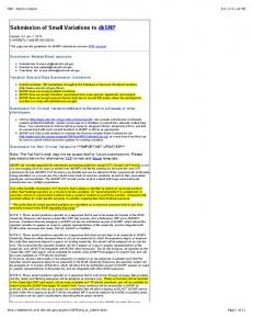
prototype into the realm of full-‐scale applica?on. Each technique is adapted it to a northern coastal climate and each is tested by using minimal materials Figure 1: End view of lamella structure, 20w x 70l x 17h.
and by monitoring its behaviour over ?me. There is a significant teaching by-‐product. Any project placed in the context of research agenda develops an important pedagogical intent that enhances the standard Design-‐Build mantra of “learning by doing” to an augmented Design-‐Build intent of “learning by experimen?ng.” Coincidently, it moves the Design-‐ Build studio into a subject for diffusion research, the topic of this conference.
1930s. It was designed by Gustel KeiwiW. St. Louis was also the loca?on of a 1929 arena designed by KeiwiW where the lamella sprang from 20 steel trusses so that eventually 15,000 seats had an unrestricted view of the ice surface. 4 The arena lasted seventy years and KeiwiW went on to build many more lamella structures including the Astrodome. Alvaro Siza’s 2005 pavilion at the Serpen?ne uses a similar geometry but the individual components vary.5 And finally, given our situa?on as a student-‐built project, we spent some ?me studying the two buildings built by Auburn’s Rural Studio in western Alabama.
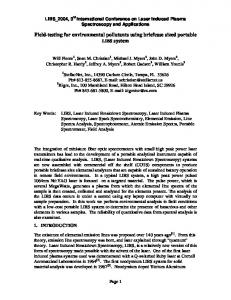
Figure 2: Installing the polycarbonate in a shingle paWern.
HISTORY OF LAMELLA VAULTING AS A STRUCTURAL SYSTEM “Lamella structures owe much to Friedrich Zollinger (1880-‐1945), Town Building advisor (1918-‐1921) for Merseburg / Saale, Germany who patented his “Zollbau” ?mber lamella housing roofs in 1921. He later developed the system for larger span roofs (typically around 30m span in a ?ed arch format) which were adopted widely in the 1920’s and 30’s in Europe and America.”1 Hugo Häring used a wood lamella structure on a one story concrete frame at the Gut Garkau farm of 1923-‐1926.2 Between 1936 and 1939 Pier Luigi Nervi built a number of aircrai hangars using precast concrete lamellas.3 The building historian, Jesse Francis, showed me a barn in Faust Park in St. Louis in 1994: he said that this was one of the few remaining examples of a building type that spread across the mid west in the 1920s and
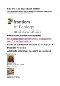
Figure 3: The lamellas in place with temporary horirontals.
HISTORY OF TIMBREL VAULTING AS A STRUCTURAL SYSTEM The ?mbrel vault was “developed in the 14th century around the Mediterranean, although its precise origins are unknown. The ?mbrel vault is also known as a "masonry vault", "Catalan vault", "?led vault", "laminated vault", "flat vault" and "layered vault"… The ?mbrel vault does not rely on gravity but on the adhesion of several layers of overlapping ?les which are woven together with fast-‐seong mortar. If just one layer of thin ?les was used, the structure would collapse, but adding two or three layers makes the resul?ng laminated shell almost as strong as reinforced concrete.”6 Again this European technique was imported to North America. “In the 1860s Rafael Guastavino, an architect trained in Barcelona, turned a folk tradi?on into an industrial building technique. He revived a
INNOVATIVE STRUCTURES AND THE DESIGN-BUILD MODEL OF TEACHING 3
tradi?onal Mediterranean thin-‐?le structural masonry technique and used it to build spans for factories in Catalonia during its industrializa?on. … [influencing] Antoni Gaudi, Josep Puig I Cadafalch, Lluis Muncunil, Lluis Domenech y Montaner, Cesar Mar?nell and many others. Guastavino emigrated to the United States … bringing with him his innova?ons in ?mbrel vaul?ng. … [and] built many great public and private spaces in the US between the 1880s and 1962, the year the company closed its doors. As specialist designers and contractors to many prominent architects, such as McKim Mead & White, Heins & Lafarge, Cass Gilbert and others, the company used its patented thin-‐?le vaul?ng system to create soaring structural masonry spans in over 1000 buildings, located primarily in the United States, but also in ten countries around the world.”7 Prominent among the examples of this technique are the Cuban Art Schools and the Mapungubwe Interpreta?on Center in South Africa by Peter Rich and Philipe Block.8 And finally, Michael Ramage, doing his Masters at M.I.T. when ?mbrel vaul?ng, Guastavino, and the work of Eladio Dieste was being studied, has been involved in the construc?on of a couple of domes built in the south of England at Pines Calyx,
COMPARATIVE HISTORY AND STRUCTURE Both systems emphasize span with an economy of materials, lightweight in comparison to trebeated construc?on due to their three-‐dimensional distribu?on of forces. Historically, each system an?cipated and was substan?ally replaced by advances in construc?on such as space frame or precast concrete. The lamella is lighter and quicker to build than the ?mbrel vault and this is evident in the fact that it took half the number of hours of labour. Shop work could be done before assembly of the lamella (assembly leaves a cleaner site than construc?on). Furthermore, following David Pye, this dis?nc?on can be described in terms of predetermina?on that locates much more of the work of dexterity and judgment in the manufacture of the lamellas and in some of the imported manufactured material such as the sheet materials used for cladding. Nevertheless, each BTES AT ACSA 2012 – DIFFUSION RESEARCH
individual lamella was a combina?on of low-‐tech and high-‐tech cuong technology: the outer perimeter was cut by hand using a circular saw and jig; the angled ends were more precise using a compound mitre radial arm saw; and the bolt holes and slots were drilled using computer-‐aided precision tools. The form chosen for the ?mbrel construc?on was similar to the lamella. Each was fundamentally axial with the structure bearing con?nuously at or near the ground. Neither system demands this; the lamella could have been supported on columns instead of founda?on piers and, likewise, shallow ?mbrel vaults are oien constructed that touch down along beams or even on columns. Both systems can be, and usually are, super structure above a ground floor that allows transverse as well as axial circula?on. The precedents above, Nervi, Haring, and Guastavino all spring from walls and columns. A barrel vault is naturally generated by the lamella and its geometry is much more restrained than the large range of possible ?mbrel vaults. The lamella structure had a geometrical rela?onship between angle of bolt, degree of angle at the end of each individual lamella, length of the lamella, and the total span of the structure – thus the piece repeated and determined the whole. In the ?mbrel vault, a set of formal restraints was applied that was not necessary to the system of construc?on. Thus, the whole was determined by the added constraint of crea?ng a catenary arch that was supported at the ground, arches that smoothly progressed in sec?on from large to small. Effec?vely, the catenary form aWempted to resolve all forces into compression and retain all
Figure 4: Lamella interior.
4 INNOVATIVE STRUCTURES AND THE DESIGN-BUILD MODEL OF TEACHING
forces within the cross sec?on or 10 cm. thickness. Similarly, in the wood structure: “All of these lamella roofs adopted very simple bolted connec?ons and the roof plane was primarily carrying in-‐plane compression.”9 Essen?ally, both are structures in compression. SITUATION -‐ LAMELLA PROGRAM AND CLIENT The 2010 project is a shelter for eighty children where they eat meals during their stay at a theatre and art camp. The main building of the arts centre has several theatre/gallery/studios spaces, one of which had been given over to dining for the campers during the summer. Our structure frees up this space so that it could return to its original use. The centre hosts resident ar?sts and arts companies. Ac?vi?es range from holding workshops tes?ng a new piece to a complete outdoor theatre season during the summer. Ini?ally, the structure had been designed for another loca?on to shelter some bunkhouses that we had designed in 2006. Building approval to place the structure in a school courtyard had been rescinded while the lamellas were being produced in the school workshop. Since the courtyard protected the structure from the 150 mph winds, we felt the type of construc?on was no longer viable for the loca?on and, as a result, we offered the building to another community theatre group. It has since weathered a force one hurricane in its current loca?on, half the wind speed of the other, with no damage what so ever.
Figures 5 and 6: incoming and high ?de, one hour interval.
SITUATION -‐ BRICK SHELL PROGRAM AND CLIENT The project is to be used as a camera obscura viewing the amazing ?dal landscape. In this situa?on, the ver?cal rise of water is dynamically translated into an extensive horizontality. Nowhere is ?me so evident as on the Fundy shore with a ?dal varia?on of over 50 feet. Just under twice a day, and for an amazing hour or so, water occupies the landscape. A small river, barely no?ced, becomes a salt-‐water lake. Great horizontal distances are covered as the water moves ver?cally over the shallow incline of the landscape. The transla?on of the ver?cal rise of 50 feet covers a distance of over a mile. This twice a day cycle of fiiy feet in height from high to low ?de is recorded through the device of the camera obscura. Observa?on is enhanced by the introduc?on of various markers, real ?me measuring devices and objects recording points in recent ?dal and solar cycles or recent random weather events. A seven year longitudinal study of the conversion of the fresh (brackish) marsh to salt is nearing comple?on.10 It is for a non-‐for-‐profit community-‐based society advoca?ng the restora?on and interpreta?on of the ?dal salt marsh at the mouth of a river. The loca?on is a historic stopping place for tourists and shore residents alike. Its view of Cape Split is sensa?onal, the long beach for recrea?onal use is alluring, and the trails along the River appeals to birdwatchers and hikers.
INNOVATIVE STRUCTURES AND THE DESIGN-BUILD MODEL OF TEACHING 5
There are many camera obscura pavilions in the world ac?ng as tourist des?na?ons. In our case, the image of the marsh is displayed on a viewing table in the centre of the pavilion and a guide can point and draw on the table as a way of explaining ac?vity on the marsh in real ?me. In addi?on, the pavilion will be able to project images on to the table captured at high ?de or in other seasons. The use of a recording device to register the site is par?cularly appropriate where there is a fiiy-‐foot ?de only evident for a few hours a day. The structure extends into the landscape and will create a small outdoor theatre for nature talks, a point of orienta?on for the trails built on the seven-‐hectare site.
took two skilled carpenters three months and eight others two months to build the lamella dining pavilion for a total of 14 man-‐months. On the other hand, the brick shell occupied seven unskilled workers two months and required a second, later crew of four unskilled workers for 3.5 months to complete the project adding up to a total of 28 man-‐months. The nature of the wood structure allowed for pre-‐ manufacturing or shop work of making the thousand or so lamellas to take place in the winter before the 2010 building season. The construc?on system dis?nguished between structure and cladding in a way that the brick vault was unable to do. During the
Figures 8: Entry under construc?on as of October 2011.
Figures 7: Laying ini?al layer.
COMPARING PROJECTS AND STUDIOS A comparison between the two projects shows substan?ve differences. Fiiy percent more students were involved in the wood lamella. Engineering was equal, but the drawings of the concrete slab suppor?ng the masonry vault were more complex. It BTES AT ACSA 2012 – DIFFUSION RESEARCH
course of construc?on, conversa?ons and group mee?ngs were clearly about detailed design development. Very few of the decisions about cladding had been resolved before the structure was built, but there was sufficient ?me to resolve details during the course of construc?on. This encouraged us to build mock-‐ups and try different op?ons. The lamella structure showed a clear affinity with contemporary North American design and construc?on, thus the language of layering was understood and available. The students were asked to report on different aspects of the building recording the various debates and alterna?ve solu?ons during design development, such things as primary structure, secondary structure, cladding, and construc?on sequence.
6 INNOVATIVE STRUCTURES AND THE DESIGN-BUILD MODEL OF TEACHING 27'-7 1/4"
8-1/4"
5'-10 1/2" 4'-8 3/4"
8'-2"
8'-1 1/4" 7'-2 1/4"
2'-6 3/4"
2'0"
7'-3 1/2"
5'-10 1/2" 4'-8 3/4"
8'-1 1/4" 7'-2 1/4"
8'-2"
3'-7 3/4"
R4'9"
6'9" 6-3/4"
2' 2-1/4"
2'-9 1/4" 2'-9 1/4"
In contrast to the wood lamella structure, twenty to twenty-‐five percent of the effort in the brick vault was in the floor and founda?on work that included a solar-‐heated slab. Since we formed materials on site, the site showed much more evidence of construc?on. A large part of the design conversa?on involved ways of accomplishing the desired pre-‐determined form. The materials (and our inadequate experience) resisted easy solu?ons to ?ght compound curves that we had to build for the floor slab’s wooden formwork. The lack of carpentry experience made even the scaffolding a building challenge for the students. It had to allow access to work inside and outside on the constantly changing vault. The crai of bricklaying, while not conven?onal in our applica?on, came to the forefront. We worked with the imprecision of brick (our thin bricks curved in two direc?ons), the influence of sun and humidity, and design of the mortar mix. In the lamella structure, Figures 7 and 8: Sec?on and plan of camera obscura. design development created logically similar or hierarchically arranged resolu?ons. In the brick shell, it became design crai that worked with nuance and grain to develop design occasions based on the encounters of phenomena. The hand of the individual was evident especially due to our varying skill, experience, and choices. The students were asked to record their daily ac?vity in a log book partly because the structure did not promote the intellectual abstrac?on of debates and alterna?ve solu?ons to the design development.
7'-9 1/2"
9'-7 1/4"
2'0"
5'-4"
14'11"
11" 11 1/4" 10 1/4"
22'-3 1/4"
Figures 9: Plan, entry from lei, smaller room is camera
References 1
Buro Happold, “Hounslow East Timber Lamella Roof Structure,” case study, Trada Technology, hWp:// research.Wlchiltern.co.uk/pif294/tdk/case%20studies/ h o u n s l o w % 2 0 e a s t % 2 0 ? m b e r % 2 0 l a m e l l a % 2 0 ro o f %20structure/01%20small.htm 2 Blundell-‐Jones, Peter. Modern Architecture through Case
Studies (Boston : Oxford Architectural Press, 2002). 3
Robert Marks, General Structures 2 & Lateral Forces (Kaplan AEC Architecture, 2004). See also Richard Bradshaw; David Campbell; Mousa Gargari; Amir Mirmiran; and Patrick Tripeny, “Special Structures: Past, Present, and Future, “ The Journal of Structural Engineering, 128/6, June 2002 and Wolfgang Schueller, Horizontal-‐span Building Structures, (New York: Wiley, 1983). 4 C.D. Stelzer, “Bringing the Roof Down” Riverfront Times,
Feb 10, 1999 hWp://www.riverfronomes.com/ content/printVersion/107286/
NOTES Figure References Figure 1: Photo by MaW Kennedy. Figure 2: Photo by author. Figure 3: Photo by author. Figure 4: Photo by author. Figure 5: Photo by author. Figure 6: Photo by author. Figure 7: Photo by author. Figure 8: Photo by author. Figure 9: Drawing by Deborah Montgomery..
5
Mar?jn Veltkamp, Free form structural design: schemes, systems & prototypes of structures for irregular shaped buildings, Research in Architectural Engineering Series, Vol. 6, (Amsterdam: IOS Press, 2007), p.54. 6 Kris De Decker, “Tiles as a subs?tute for steel: the
art of the ?mbrel vault” Low Tech Magazine, November 2008. 7
Michael H. Ramage, “Guastavino’s Vault Construc?on Revisited,” unpublished, 2007. See also, Lara Davis, 2010, “ B u i l d i n g t h e S u d u , ” hWp:// sudu1construc?on.wordpress.com/2010/11/12/applied-‐ structures-‐i-‐sudu-‐design/
INNOVATIVE STRUCTURES AND THE DESIGN-BUILD MODEL OF TEACHING 7
8
J. A. Loomis. RevoluHon of Forms: Cuba’s ForgoJen Art Schools. (New York: Princeton Architectural Press, 1999), a n d f o r t h e w o r k o f P e t e r R i c h s e e h W p : / / www.frameandform.com/en/2009/11/23/centro-‐de-‐ interpretacion-‐mapungubwe-‐en-‐sudafrica/ 9 Buro Happold, “Hounslow East.” 10 Tony Bowron, Nancy NeaW, Danika Van Proosdij, Jeremy
Lundholm, Jennie Graham “Macro-‐Tidal Salt Marsh Ecosystem Response to Culvert Expansion” RestoraHon Ecology, Wiley, first published online: 21 Oct 2009
BTES AT ACSA 2012 – DIFFUSION RESEARCH


![Submit Reset [PDF]](https://m.moam.info/img/260x300/submit-reset-pdf_647a025f098a9e30208b463a.jpg)