chanical support, cooling systems, RF shielding, flex-cable feedthrough, and .... [2] Energy Science Labroatories, Incorporated (ESLI), San Diego, CA 92121.
BTeV Silicon Detector Integration Issues Mayling Wong, Joe Howell, Cary Kenziora, Simon Kwan, C.M. Lei, Alex Toukhtarov Fermi National Accelerator Laboratory PO Box 500, Batavia, IL 60510, USA Mauro Marinelli Department of Physics INFN Via Dodecaneso 33, 16146 Genova, ITALY Charles Newsom Department of Physics and Astronomy University of Iowa 203 Van Allen Hall, Iowa City, IA 52242, USA
1
Introduction
The BTeV silicon pixel detector contains 30 planar stations that reside inside the vacuum of the Tevatron machine close to the beam. The detector sits within the analysis magnet. The location of the detector leads to unique constraints on the mechanical support, cooling systems, RF shielding, flex-cable feedthrough, and vacuum system. The design is based on these constraints and a number of technical specifications required of the detector. The baseline design was presented at the Pixel 2002 Conference.
2
Technical Specifications
The BTeV silicon detector contains 1600 electrical cables that will carry signals to and from the detector. The heat load from each readout chip is 0.5 W/cm2 for a total heat load from the detector of 2.5 kW. A cooling system will keep the operational temperature between −5 ◦ C and −10 ◦ C and will be reproducible to ± 2 ◦ C. The pixels reside inside a vacuum vessel, which has a pressure of 10−7 torr. The detector sits within the analysis magnet with a field of 1.6 T. The pixels are as close as 6 mm from the beam line during operation. During beam injection, the pixels are moved 20mm away by the actuator system. Typically, it is expected that the pixel dectector will be moved about once per day. The position of the pixels must be reproducible 1
to less than 50 µm. The pixels must be mechanically aligned within 50 µm. The pixels must be stable to less than 2 µm during operation. Finally, an RF shield is required between the pixel detector and the circulating beamsfor adequate protection from electromagnetic effects. The spectrometer has an acceptance angle of ±300x300 mrad2 . Thus, all material within this angle have to be minimized in order to reduce primary interactions. The material amount expected for the area within the acceptance angle is 1.25% of a radiation length per plane of silicon [1].
3
Substrate
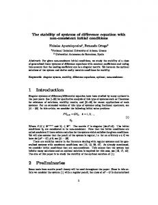
The silicon pixels reside on substrates, as shown in Figure 1. There are two substrates per station for a total of 30 stations (60 substrates) in the detector. The surface of the substrate is shingled for full coverage in the active area. The substrates are offset from each other along the beam 4.25cm. During operation, the substrates lie such that the beams travel through a hole between the substrates. The hole is a 12x12 mm square. The substrates move away from the beam line during injection.
Figure 1: Layout of substrates.
The baseline substrate material is made of is ”fuzzy carbon,” a proprietary carbonbased material made by ESLI [2]. Figure 2 shows a prototype substrate made of fuzzy carbon. Carbonized fibers are aligned in specific directions according to the strength of the material. The material’s radiation length is just 0.02% for a thickness of 0.88 mm, making the radiation length relatively high at 440 cm. Fuzzy carbon’s coefficient of thermal expansion is similar to that of silicon. This eliminates CTE mismatch problems within the assembly, such as when the assembly takes place at room temperature and then is cooled to −5 ◦ C during operation. Although fuzzy carbon is the baseline material for the substrates, the material is available only from a single vendor. So other materials are being considered for the substrate, such as beryllium. Beryllium is certainly more robust, but its radiation 2
Figure 2: Prototype fuzzy carbon substrate with embedded cooling lines.
length is lower than that of fuzzy carbon. A prototype beryllium substrate has been made. Carbon foam and pyrolytic graphite are also being considered as alternative carbon based materials to fuzzy carbon for the substrate.
4
Cooling System for the Pixels
In order to keep the silicon pixels in the temperature range of −10 ◦ C to −5 ◦ C, a cooling system containing water glycol will be used. The coolant will contain 40% glycol by volume and will flow at a rate of about 1 L/min through each substrate. Note that the prototype shown in Figure 2 shows cooling tubes running through the substrate. For the substrate’s baseline fuzzy carbon design, the cooling tubes are made of glassy carbon, another proprietary carbon-based material made by ESLI.
5
Support Structure
The substrates are held in place by a carbon fiber support half cylinder, as shown in Figure 3. Carbon fiber brackets are fixed to the ends of the substrates by screws and glued to the support cylinder. A finite element analysis of the support cylinder shows that the cylinder has a maximum displacement of 0.057 mm when loaded by the weight of the substrates and by its own weight. The lay-up of the fibers is designed to minimize the displacement.
6
Electric Cables
Pyralux AP [3] flexible cables will carry power and signal to and from the silicon pixel modules, as shown in Figure 4. Each substrate assembly will contain 28 high voltage cables.
3
Figure 3: Carbon fiber half cylinder holding substrates (aluminum only for prototype) with carbon fiber brackets.
Figure 4: Pyralux flexible cables.
7
Assembly of a Half Cylinder
Figure 5 shows the half cylinder assembly with the strain relief plate and four substrates installed. An actuator moves the cylinders, and thus the silicon detector, in the horizontal and vertical directions. The cylinders move 2 cm away from the beam line during beam injection. Note that the bellows in the cooling lines allow flexibility for movement of the cylinder assembly. The flex cables coming from the substrates are clamped to the cable strain relief plate which also acts as a heat sink. The heat sink, like the substrates, is cooled by water glycol. The total material thickness in radiation lengths for the substrate assembly is 0.17%. This total includes the fuzzy carbon substrate, the glassy carbon cooling tubes, and the water glycol coolant.
8
Electrical Feedthrough Board
There are two electrical feedthrough boards, one of which is shown in Figure 6. Each feedthrough board will have connectors for each of the electric cables from a half cylinder assembly. The feedthrough board has been shown to hold vacuum when 4
Figure 5: Assembled half cylinder showing 4 substrates (left) & the cable strain relief plate/heat sink (right).
sealed with an o-ring. A test of the seal of the board showed no leak rate with a leak detector having a minimum sensitivity 10−10 std-cc/sec for helium.
Figure 6: Assembled feedthrough board shown with vacuum vessel, rectangular ring and cover plate.
9
5% Model
In order to estimate the gas load of the detector due to outgassing, a model consisting of about 5% of the total surface area of the detector was built. Figure 7 shows photographs of the model. Six aluminum substrates held dummy pixel modules. Kapton strips were used in place of cables; one end was glued to the modules and the other end clamped to an aluminum plate. The plate acted as both a cable support and a heat sink. The substrates and aluminum plate were cooled independently of each other. The gas load was measured at various temperatures. The model was placed inside a vacuum chamber that had turbomolecular pumps with a total pump speed of 1300 L/sec of nitrogen. 5
Figure 7: 5% Model
Cooling the heat sink to −160 ◦ C with liquid nitrogen resulted in a vacuum pressure of about 10−9 torr, regardless of the substrate temperature. The heat sink acted as a cryopump that had a pump speed of 19,000 L/sec for water. Using a cryopanel, or a plate that is cooled to cryogenic temperatures and acts as a cryopump, allows the detector to reside inside the pixel vacuum chamber that shares the accelerator vacuum. The cryopanel has enough pumping capacity to bring the vacuum pressure to the specified 10−7 torr.
10
RF Shield
The baseline design of the RF shield is a corrugated shield made of 150 µm thick aluminum. Figure 8 shows a three-dimensional model of the RF shield. The corrugated side that is shown is the side that is exposed to the beam. The substrates would be placed on the other side of the corrugations. Since the detector will reside in a vacuum that is shared with the beam vacuum, the RF shield does not need to be leak tight.
11
Prototype Actuator
A prototype, air-controlled actuator has been built (Figure 9). Two step sizes are available: 1 and 10 µm. It takes 4 minutes to move 2 cm using the larger step size.
12
BTeV Silicon Detector
Figure 10 shows one half of the assembled detector. The vacuum vessel that contains the detector has dimensions 1.65m in length, 0.60 m in height, and 0.60 m in width. The vessel is made of stainless steel. Six actuators, three actuators for each half 6
Figure 8: Model and prototype of RF shield.
Figure 9: Prototype actuator.
cylinder, will move the detector before and after beam injection. The cryopanels lie along the top and bottom walls of the vessel. The silicon detector lies behind the RF shield. Electrical feedthrough boards make up the side walls of the vacuum vessel.
13
New Development Steps
A baseline design for the mechanical, vacuum, and cooling systems of the silicon detector was been established. However, research and development continues on issues that may modify the design. EMI issues must be studied in order to optimize the design of the RF shield. The format of the RF shield may change, perhaps becoming a mesh or a set of wires. The design must be worked on in conjuction with the Fermilab Beams Division. Electrical feedthrough boards make up part of the wall of the vacuum vessel. An assembly procedure for the boards must be developed to ensure that the boards are leak-tight across the entire 1.65 m length. One possibility is to have the board be made of six smaller boards that are glued together. Another possibility is to have six separate boards that are individually sealed to the vacuum vessel with o-rings. The cryogenic system that cools the cryopanel is a recent addition to the design. 7
Figure 10: Assembled BTeV silicon detector - one half shown.
Work is taking place to investigate if the silicon cooling system can be integrated into the cryopanel system so that the silicon is cooled to the temperature range of −5 ◦ C to −10 ◦ C. The advantage would be to eliminate the numerous water-to-vacuum joints and the possibility of water-glycol leaking into the vacuum. The design requirements for the BTeV Silicon Detector make the detector’s integration complex and challenging. A design of the mechanical, vacuum, and cooling systems exists for the detector. Development work continues in preparation for the beginning of construction, scheduled for Fall, 2004.
14
Acknowledgements
A project of this magnitude and complexity is successful with the help of many people. The group is grateful for the efforts, guidance and advice from J.A. Appel, S. Austin, J.N. Butler, D.C. Christian, M. Ruschman, G. Sellberg, and S. Zimmerman from Fermilab; M. Artuso and S. Stone from Syracuse University; and D. Cinabro from Wayne State University.
References [1] J.A. Appel, these proceedings. [2] Energy Science Labroatories, Incorporated (ESLI), San Diego, CA 92121. [3] DuPont Electronic Materials, Research Triangle Park, NC 27709. 8