2446
IEEE TRANSACTIONS ON MAGNETICS, VOL. 46, NO. 6, JUNE 2010
Buffer Layers for Highly Ordered L10 FePt-Oxide Thin Film Granular Media at Reduced Processing Temperature En Yang, David E. Laughlin, and Jian-Gang Zhu Data Storage System Center, Carnegie Mellon University, Pittsburgh, PA 15213 USA In this work, we present an experimental technique for obtaining highly ordered L10 FePt-oxide thin film media at moderate deposition temperatures. In most previous studies, a FePt-Oxide layer is directly deposited on a (001) textured MgO layer. By introducing a buffer layer in between the FePt-oxide layer and the MgO underlayer, we are able to substantially enhance the L10 ordering of the FePt-oxide layer while lowering the deposition temperature to 400 C. The buffer layer also yields a significantly enhanced (001) texture of the formed L10 FePt structure. With the order parameter near unity, the coercivity of the resulting granular L10 FePt-oxide film 20 kOe with an average grain size about 8 nm. With the buffer layer technique, 18kOe coercivity has also been achieved exceeds for L10 FePt-oxide film at a grain size of about 4.5 nm. In this work, the detailed material composition choice of the buffer layers and the corresponding results are presented.
Hc
Index Terms—FePt, magnetic recording, thin films.
I. INTRODUCTION HE FePt L1 material has been suggested as a potential thin film media candidate for future hard disk drive applications due to its extremely high magneto-crystalline anisotropy [1], [2]. In order to use it as a high density recording media, very small (less than 5 nm), uniform and fully ordered, magnetically isolated FePt L1 columnar grains with excellent perpendicular texture and high coercivity are desired. If it is deposited at room temperature, the FePt thin film is usually is not atomically ordered, but is in the fcc structure. Either high deposition temperature, 600 C, or a post annealing process at similar temperatures is required to obtain the ordered L1 structure [3], [4]. Such high processing temperature limits the use of Al substrates which have been used for a long time. Therefore, techniques that enable ordering at significantly reduced temperatures are critically and urgently needed. Not only is ordering to the L1 phase at lower temperatures important to the development of FePt films, but in order to work as a thin film medium at ultrahigh area recording densities for hard disk drive application, the film needs to be granular in nature of uniform sized grains with well-defined grain boundaries. In this paper, we present an experimental approach for obtaining highly ordered L1 FePt-oxide perpendicular thin film media at moderate deposition temperatures (400 C) with very small grain size (4.5 nm).
T
II. EXPERIMENTAL RESULTS AND DISCUSSION In this experimental study, we use RF sputtering for all the film deposition processes. The base pressure is about Torr and the argon pressure is varied between 10 to 65 mTorr. For producing FePt L1 film with (001) texture, a layer of MgO with (002) texture is commonly used. The central part of this work is to introduce a thin layer of Ag with the (002) texture in between the MgO layer and the FePt layer. The Ag buffer Manuscript received November 01, 2009; revised February 03, 2010; accepted February 05, 2010. Current version published May 19, 2010. Corresponding author: E. Yang (e-mail:
[email protected]). Color versions of one or more of the figures in this paper are available online at http://ieeexplore.ieee.org. Digital Object Identifier 10.1109/TMAG.2010.2043070
layer is epitaxial grown on the MgO underlayer with the (002) texture by RF sputtering at room temperature. A FePt + oxide layer is then deposited on top of the Ag layer at an elevated temperature. The upper curve in Fig. 1(a) shows the X-ray diffraction data on the Si\18 nm MgO\2 nmAg\5 nm FePt film stack. The case without the Ag buffer layer is also shown for comparison. The substrate temperature of the FePt layer deposition only is 400 C for both the cases w/ and w/o the Ag buffer layer. In the case with the 2 nm Ag buffer layer, a substantially higher order parameter, measured by the integrated ratio of the FePt (001) peak to the (002) peak, has been obtained, compared with the FePt layer directly deposited on the same MgO underlayer at the same substrate temperature [5], [6]. This indicates that the Ag buffer layer results in a significantly enhanced order parameter of the FePt film. From the figure, the position of the FePt(002) peak is shifted to much higher angle with the Ag buffer layer inserted. Compared to the FePt(002), FePt(001) peak did not shift, indicating the lattice parameter c did not change. Therefore, shifting of (002) peak is not a result of lattice contraction along c-axis. In fact, the third peak at 47 in these MgO\FePt+SiO films is a mixture of the FePt fcc(200), FePt L1 (200) and FePt L1 (002). The shifting of this peak indicates less fcc phase in the film and less L1 FePt(200) in-plane variants. When Ag buffer layer is inserted, the lattice parameter c calculated from FePt(001) peak is the same as from FePt(002) peak, indicating FePt(002) peak in MgO\Ag\FePt+SiO2 film has no other peak overlapping. The excellent perpendicular texture was confirmed by in-plane XRD scan in Fig. 1(b). Although the thin Ag buffer layer significantly enhances the order parameter and the texture of the FePt L1 layer, the resulting microstructure of the FePt layer after the deposition is actually not desirable. Fig. 2(a) shows a cross section TEM micrograph of the FePt layer and the layer has been broken into very small magnetic grains. After a systematic experimental investigation, two ways have been found to overcome this shortcoming. One is to have sufficient percentage of oxide, such as SiOx, in the FePt layer. The other is to introduce an additional buffer layer: a thin oxide layer, on top of Ag prior to the deposition of FePt + oxide. Furthermore, increasing the oxide volume fraction in the magnetic layer can efficiently decrease the FePt grain size. Fig. 2(b) shows the results with the oxide/Ag double
0018-9464/$26.00 © 2010 IEEE Authorized licensed use limited to: Carnegie Mellon Libraries. Downloaded on May 25,2010 at 12:30:33 UTC from IEEE Xplore. Restrictions apply.
YANG et al.: BUFFER LAYERS FOR HIGHLY ORDERED L1 FePt-OXIDE THIN FILM GRANULAR MEDIA AT REDUCED PROCESSING TEMPERATURE
2447
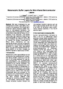
Fig. 2. Cross-section TEM picture of (a) FePt-oxide layer deposited on top of an Ag buffer layer (b) FePt-oxide layer deposited on top of an oxide/Ag bilayer (c) XRD of film (b). The thin oxide layer yields a good preservation of the granular structure of the FePt-oxide layer, yet still achieves high ordering and excellent crystalline texture.
Fig. 1. (a) Red: X-ray diffraction data of the FePt layer deposited at 400 C on top of 2 nm Ag buffer layer, showing excellent L1 ordering and crystalline texture. Blue: XRD of the FePt layer deposited at 400 C directly deposited on MgO layer without the Ag buffer layer, showing less well ordered L1 ordering. (b) In-Plane XRD scan of FePt layer deposited at 400 C on top of 2 nm Ag buffer layer.
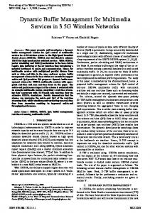
buffer layers and 35% oxide in the FePt film. The cross section TEM of the resulting FePt-oxide layer shows well preserved granular structure with grain size of 4.5 nm and a narrow particle size distribution of 1.2 nm in standard deviation; no break-up of the grains through the entire depth of the FePt layer: i.e., the FePt grains are essentially columnar. The X-ray diffraction still shows very high order parameter and excellent (001) texture of the L1 FePt layer as shown in Fig. 2(c). Fig. 3 shows the measured hysteresis curve for the film stack shown in Fig. 2(b) with the oxide/Ag double buffer layers. The hysteresis curve shows a nucleation field greater than 10 kOe and a coercivity 18 on Si substrate and 21 Koe on glass substrate. Part of the motivation to introduce the Ag buffer layer is the reduction of lattice mismatch between MgO (001) and FePt L1 (001). Previously, the c axis normal configuration was obtained by growing FePt onto (002) MgO underlayer to symmetry match the fourfold FePt basal plane with the MgO [3], [6]. The lattice misfit for FePt(001)/MgO(002) is about 9%. By introducing the Ag buffer layer, the lattice misfits for FePt(001)/Ag(002) and Ag(002)/MgO(002) are 6% and 3%, respectively. The reduced lattice mismatch is believed to attribute to the enhanced FePt[001] texture.
Fig. 3. Magnetic hysteresis loop measurement of a FePt-L10+oxide film deposited on an oxide/Ag double buffer layer.
The most interesting phenomenon in this experimental approach is the “floating” behavior of Ag layer. After the completion of the top FePt L1 layer deposition, the sample surface has a dusty non-mirror appearance. The ‘dust’ on the surface can be wiped off very easily by a gentle wiping. After wiping the dust off, the sample regains the clean mirror surface. Fig. 4(a) shows the XRD of the same sample before and after cleaning. The Ag(200) peak and AgO peak disappear after cleaning, indicating Ag buffer layer has been cleaned off! From the TEM cross section images shown in Fig. 4(b) and (c), Ag dust on top of FePt layer disappeared after cleaning process. Further
Authorized licensed use limited to: Carnegie Mellon Libraries. Downloaded on May 25,2010 at 12:30:33 UTC from IEEE Xplore. Restrictions apply.
2448
IEEE TRANSACTIONS ON MAGNETICS, VOL. 46, NO. 6, JUNE 2010
Fig. 5. EELS mapping of Ag for MgO\Ag\SiO2\FePt+Sio2 film stack after cleaning.
Fig. 4. (a)XRD scans of MgO\Ag\SiO2\FePt+Sio2 film stack before and after clean the surface. Cross section TEM image of (b): MgO\Ag\SiO2\FePt+SiO2 film stack before clean the surface. (c) MgO\Ag\SiO2\FePt+Sio2 film stack after cleaning the surface.
EELS element analysis proves the top dust is 100% Ag. From above experimental results, we believe that after deposition of MgO/Ag/SiO2 at room temperature and heating up the substrate to 400 C, during the deposition of the FePt layer, the Ag in the buffer layer diffuses through the FePt magnetic layer to the top of the film stack. Since the as deposited FePt is deposited as the high temperature fcc phase, it needs to overcome the activation barrier to change the disordered phase to the ordered phase. The Ag diffusion seems to provide an enhancement of the diffusion and therefore improves the order parameter of FePt”. It is evident that the “floating” process of Ag layer during the deposition of the FePt layer results in enhanced atomic ordering of the FePt L1 structure as well as improving its crystalline (001) texture, or [001] orientation. Further experiments found that thickness of the Ag buffer layer influences the FePt order parameter greatly; a thicker Ag buffer layer yields higher order parameter and higher coercively of FePt L1 film. The Ag diffusion behavior can also cause degradation of the FePt columnar microstructure if there is not enough oxide in the FePt magnetic layer, which explains the undesirable microstructure without using sufficient oxide in Fig. 2(a). The film morphology can also be degraded as too much Ag diffuses down into MgO underlayer. The Ag buffer layer may also be called as a sacrificial layer since it performs its desired function during the film deposition and disappears from the final film stack. According to the above discussion, traces of the Ag layer should be found in the film stack. In Fig. 5, a Ag EELS mapping shows there is a residual Ag layer left on the surface of
film stack, in between the MgO underlayer and the FePt L1 layer, and in the FePt grain boundaries. Ag was also found inside the MgO under layers, indicating Ag also diffuses down into MgO underlayer, which explains the film roughness as shown in Fig. 2(b). It is well known that particle size can directly affect equilibrium properties. When particles reach sub-ten nanometer, crystallographic structure, and local composition can significantly vary with size. Moreover, particles supported by different underlayers or surrounded by different oxides can again reveal different behavior. The local composition inside the grains can change and vary from grain to grain because of different chemical surroundings. In our early work, EDAX quantification re, sults revealed that in very small FePt grains surrounded by the composition inside the single grain is not uniform, a preferential surface segregation of Fe atoms was observed. When Ag covers the FePt grains, it might provide a different driving force for Pt and Fe surface segregation behavior, therefore providing the proper composition for FePt L1 ordering, and results in a small grain size with high coercivity.
III. SUMMARY We have presented an experimental investigation on the effect of inserting a thin Ag buffer layer in between the FePt L1 magnetic layer and the MgO underlayer with (002) texture of the conventionally adopted film stack. The introduction of the Ag buffer layer yields significantly enhanced order parameter for the FePt L1 layer deposited at moderate substrate temperature along with significantly enhanced texture. However, the Ag buffer layer addition also causes the columnar granular structure to break into 3-D multilayered structure with very small grain size separated by Ag. With the addition of SiOx into FePt L1 film, a columnar structure of the magnetic layer is preserved and the grain size appears to be inversely proportional to the volume percentage of the oxide in the layer. It is also found
Authorized licensed use limited to: Carnegie Mellon Libraries. Downloaded on May 25,2010 at 12:30:33 UTC from IEEE Xplore. Restrictions apply.
YANG et al.: BUFFER LAYERS FOR HIGHLY ORDERED L1 FePt-OXIDE THIN FILM GRANULAR MEDIA AT REDUCED PROCESSING TEMPERATURE
that the Ag buffer layer is completely dissolved at the completion of the oxide-FePt L1 layer deposition and Ag re-precipitates at the top of the completed film in the form of particulates which can be easily removed. It is concluded that the Ag buffer layer enables near unity atomic ordering of the oxide-FePt L1 at moderate deposition temperature and high coercivity can be achieved at small grain sizes. ACKNOWLEDGMENT This work was supported in part by the Data Storage Systems Center and its industrial sponsors. The authors would like to thank Dr. T. Klemmer and Dr. G. Ju for their support and helpful discussions in this project. The authors also would like to thank Dr. G. Ju for conducting the magnetic hysteresis measurements shown in this paper.
2449
REFERENCES [1] J. A. Christodoulides, P. Farber, M. Daniil, H. Okumura, G. C. Hadjipanayis, V. Skumryev, A. Simopoulos, and D. Weller, “Magnetic, structural and microstructural properties of FePt/M (M = C, BN) granular films,” IEEE Trans. Magn., vol. 37, pp. 1292–1294, 2001. [2] N. Ishiwata, C. Wakabayashi, and T. Matsumoto, “Zero magnetostriction iron films,” Ieee Trans. Magn., vol. 24, pp. 3078–3080, 1988. [3] Y. N. Hsu, S. Jeong, D. N. Lambeth, and D. E. Laughlin, “In situ ordering of FePt thin films by using Ag/Si and Ag/Mn3Si/Ag/Si templates,” IEEE Trans. Magn., vol. 36, pp. 2945–2947, 2000. [4] Y. F. Xu, J. S. Chen, and J. P. Wang, “In situ ordering of FePt thin films with face-centered-tetragonal (001) texture on Cr100-xRux underlayer at low substrate temperature,” Appl. Phys. Lett., vol. 80, pp. 3325–3327, 2002. [5] E. Yang and D. E. Laughlin, “L1(0) FePt-oxide columnar perpendicular media with high coercivity and small grain size,” J. Appl. Phys., vol. 104, pp. 023904–023904-3, 2008. [6] Y. G. Peng, J. G. Zhu, and D. E. Laughlin, “L1(0) FePt-MgO perpendicular thin film deposited by alternating sputtering at elevated temperature,” J. Appl. Phys., vol. 99, pp. 08F907–08F907-3, 2006.
Authorized licensed use limited to: Carnegie Mellon Libraries. Downloaded on May 25,2010 at 12:30:33 UTC from IEEE Xplore. Restrictions apply.