Abstract. In case of one-way streaming media applications over IP networks, it is well known that pre-buffering at the receiver side is very effective in overcoming ...
Buffer Level Estimation for Seamless Media Streaming in Mobile IPv6 Networks Dongwook Lee1 and JongWon Kim2 Gwangju Institute of Science and Technology (GIST), Gwangju, 500-712, Korea 1 UFON Research Center and 2 Networked Media Lab. {dulee,jongwon}@gist.ac.kr
Abstract. In case of one-way streaming media applications over IP networks, it is well known that pre-buffering at the receiver side is very effective in overcoming network fluctuations. However, under the mobile IP situation that faces intermittent handoff of several seconds, it is not trivial to sustain seamless playback if latency requirement is stringent. Inaccurate and conservative choice on the required margin of buffering can waste limited latency budget, resulting in overall quality degradation. Thus, in this paper, we introduce a novel scheme that helps estimate the required pre-buffer size more accurately by considering both handoff duration and transient packet losses. Network simulation shows that the proposed scheme can provide an appropriate guideline on the buffer parameters and thus can facilitate the seamless streaming over the mobile IPv6 networks. Keywords: Seamless media streaming, Mobile IP, Handoff transient time, and Pre-buffering.
1
Introduction
Mobile and wireless technologies have accelerated wide-spread adoption of multimedia services to mobile computers. In streaming applications, media streams have to be transmitted continuously, overcoming the fluctuation of network resources. The delay, jitter, and busty packet losses are usually addressed by adopting sufficient buffering at the clients prior to playout [1]. This buffering called ”pre-buffering” smoothes network variations and gives a retransmission opportunity for lost packets. Under mobile networks, available bandwidth is scarce and even fluctuating severely. In addition, Transmission itself is paused when a handoff occurs. In fact, several mechanisms are proposed to reduce the blackout period due to handoff [2, 3]. However, these schemes are limited since they require special arrangements such as MAC bridge, additional resources, and corresponding signaling. Even with the fast handoff situations described in [7], packet losses are still present due to the weak signal strength around the handoff. Thus, we need to overcome possible shortage of buffer by adopting pre-buffering techniques. However, inaccurate and conservative choice on the required buffering margin can waste limited latency budget, resulting in overall quality degradation. K. Aizawa, Y. Nakamura, and S. Satoh (Eds.): PCM 2004, LNCS 3331, pp. 139–146, 2004. c Springer-Verlag Berlin Heidelberg 2004 �
140
D. Lee and J. Kim Streaming Server
Streaming Client
Video Archive
802.11 WLAN
Rate Adaptation
Feedback Handling
Packet Scheduler
Server Buffer
Mobile IP Network AR
Display
Feedback
AR
AR
AR
AR
Pre-buffering Management
AR Mobile Node (MN) 802.11 WLAN
Monitoring & Estimation
Decoder Client buffer
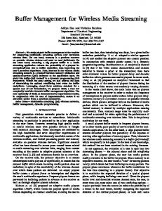
Fig. 1. Seamless media streaming framework in mobile IP networks.
In this paper, we introduce a seamless streaming framework by estimating the accurate prebuffer size to compensate the handoff latency and by adapting rate-shaping scheme to overcome the shortage of bandwidth around the handoff. We calculate the handoff latency by extending the previous work in [4] from the application point of view assuming the mobile IPv6 networks with fast handoff. Network simulation shows that the proposed scheme can provide appropriate guideline on the buffer parameters and thus can provide seamless streaming.
2
Seamless Media Streaming Framework
Fig. 1 shows the seamless media streaming framework under the mobile IPv6 networks [5], where IEEE 802.11 devices are configured as a wireless LAN infrastructure. A streaming application on a mobile node (MN) receives packets from a media server, while keeping an amount of packets in the client buffer to overcome resource fluctuations of network: available bandwidth, delay, and loss. The streaming server reacts to the feedback informed by the streaming client and performs quality adaptation, and packet schedule. The streaming client sends it’s status information to the server, which includes current buffer occupancy, receiving rate, error rate, and etc. Many studies on the relationship between feedback and reaction have been reported in [8]. In this work, we are focusing on the movement of client, handoff, which interrupts media delivery and spoils client’s streaming budget. Under the mobile IP networks, a MN that currently plays the streaming content can move beyond the reach of access router (AR) shown in Fig. 2(a). According to the received signal level, the MN initiates the handoff. At the beginning of the handoff, management frames are exchanged for a link-layer (L2) handoff between the MN and the wireless access point (AP) attached to the ARs. After the L2 handoff process, a network-layer (L3) handoff can be initiated. For the L3 handoff process, ‘Binding Update’ (BU) message is used to inform both a corresponding node (CN) and a home agent (HA) about a new location information of the MN. After the CN receives the BU message, it changes the route path from the old route destined to the previous AR (PAR) (old stream) to the new one destined to the new AR (NAR) (new stream). The packets in the old route are forwarded to the NAR via the PAR according to the fast handoff procedure. Thus, to receive the packets from the old stream, the MN should wait for an additional time as well as the L2 handoff delay. Moreover, it is known that the change of route path causes the packet sequence disruption [4].
Buffer Level Estimation for Seamless Media Streaming
141
PAR (Previous Access Router) Initial Buffering
NAR (New Access Router) Binding Update message Media Server
Monitoring & Estimation Monitoring
12 8
11 10
7
PAR
Wired Network
Target Buffer Level (BT) Estimation
9
6 5
4
3
Pre-buffering
2
Periodical Updating
Handoff
NAR IEEE 802.11b LAN
Buffering Policy Selection
1 Packet Buffering
handoff Mobile node
(a) Handoff scenario
(b) Prebuffering procedure
Fig. 2. Pre-buffering scenario.
In our framework, the handoff transient time is estimated before the handoff occurs. To estimate the handoff transient time, the mobile client monitors network conditions such as link delay, flow rate, and queue status of the neighbor ARs. The handoff protocol and related signaling procedure are analyzed to get the handoff transient time. After estimating the handoff transient time, the streaming client tries to prepares enough data to compensate the estimated interruption time during the handoff. To acquire the estimated buffer level, target buffer level, which is estimated based on the given handoff transient time, the streaming client tries to collect packets, while keeping playback of the received media packets. There are two choices to boost required target level: increasing sending rate at the streaming server or decreasing the playback speed. It depends on the policy of pre-buffering management module. The estimated buffer level can be varied along the time. Every ARs will have different required buffer level for handling handoff transient time. Even in the AR, network traffic condition can change the required buffer level. Thus, it is needed to keep the exact buffer level not to stop playback during the handoff. In Fig. 2(b), the estimation and buffer-level adjustment are performed periodically. To summarize, the pre-buffering scenario consists of buffer-level estimation procedure and buffer-level adjustment procedure as shown in Fig. 2(b). In the following section, we will analyze the handoff procedure to get handoff transient time which will be used to estimate target buffer level for pre-buffering.
3
Target Buffer Level Estimation for Pre-buffering
Handoff latency estimation: In this section, handoff latency and out-of-order packet period are estimated, which is based on the results of previous work [4]. Under the mobile IPv6 networks with fast handoff, a MN has a time period when it can not send and receive packets during handoff. We define this blackout period as the STP (silence time period). Also, we define the UTP (unstable time period) during when the packet sequence could be mis-ordered. Depending on the location of PAR and NAR, the timing between the old and new streams can be classified into three cases. As shown in Fig. 3, we can associate the transient
142
D. Lee and J. Kim Handoff Initialization
Case 1
Old stream
CN CN
Old stream
New stream
STP HTP
New stream Case 2 STP
tp
Case 3
tf
PAR PAR
UTP
HTP
tn
UTP
STP
NAR NAR
HTP
(a)
(b)
Fig. 3. Possible packet orderings observed at the MN during the handoff (for the traffic from the CN to the MN).
BU MN
tAD
tw
tn
Qn
FIRST
FIRST
BU NAR
CN
PAR
tn
Qc
MN
tw
Qn
(a) FIRST MN
tAD
NAR
Qn
tw
Qp
(b1) BU MN
tAD
tw
Qn
NAR
tf
Qn
tw
MN
(b2) LAST
LAST
BU NAR
FIRST
FRIST PAR
MN
CN
tn Q c
tp
PAR
Qp
Tf
LAST NAR
Qn
tw
MN
(c)
Fig. 4. Message flows and associated link delays for various packet streams (for the case when the MN moves from the PAR to the NAR): (a) the first packet of the new stream (for Tf new ), (b) the first packet of the old stream (for Tf old ); (b1) forwarded packet is already arrived at the NAR at the end of L2 handoff, and (b2) forwarded packet is not arrived at the NAR, and (c) the last packet of the old stream (for Tl old ).
time periods (i.e., STP, UDP, and HTP) according to link delays in NAR, PAR, and CN. For example, the ‘Case 1’ illustrates the situation where a MN moves to the far-away (in network routing sense) NAR from its CN. Thus, by setting the time when the MN leaves the PAR to zero, the STP, UTP, and HTP can be denoted by ST P = min(Tf
old ,
Tf new ), U T P = max(0, Tl old − Tf new ), HT P = U T P + ST P + |Tf new − Tf old |,
(1) (2) (3)
where Tf new is the time when the first packet of new stream arrives to the MN and Tf old and Tl old is the time when the first packet and the last packet of the old stream is delivered to the MN, respectively. The link delays between CN PAR, CN - NAR, and PAR - NAR are denoted by tp , tn , and tf , respectively. A handoff is started when a MN moves from the PAR. The bidirectional tunnel is already established between the NAR and the PAR. After the departure, there is a delay until the moved MN sends a RS message and the NAR responses it with a RA message. This delay consists of handoff latency in a link layer and a packet
Buffer Level Estimation for Seamless Media Streaming
143
Fig. 5. Handoff scenario based on channel throughput.
transmission delay. We denote the L2 handoff delay as tL2 . The propagation delay of wireless link is denoted by tw . Queueing delay of a packet in NAR, PAR, and CN is denoted by Qn , Qp , and Qc respectively. The MN can receive a packet after L2-handoff completion and RS and RA packet exchange between MN and NAR. This attachment delay is set by tAD = tL2 + 2tw . According to the delay of each message flows shown in Fig. 4, the Tf new , Tf old ,Tl old can be described as follow. Tf
= tL2 + 4tw + 2Qn + Qc + 2tn ,
(4)
= max(tL2 + 3tw , tf + Qp + Qn + tw ), = tL2 + 4tw + 2Qn + tn + Qc + tp + Qp + tf .
(5) (6)
Tf Tl
old
old
new
Packet loss estimation: Handoff is performed based on the received signal strength of received data. Fig. 5 describes a throughput profile when a MN moves to a NAR from a PAR. When a MN is moving to a NAR from an PAR, the signal strength (and related transmission throughput) from the PAR decreases [6]. It is clear that the transmission throughput of IEEE 802.11b is smallest when the MN is around handoff. The streaming client should consider the throughput degradation around a handoff as wall as the handoff processing delay described in previous section. Streaming application may not guarantee required bandwidth (so called the source sending rate at time t, Rs (t)), around a handoff. Accordingly, when the throughput is less than Rs (t), the packets sent by a streaming server will be lost. The throughput of the PAR channel is less than Rs (t0 ) at t0 and the MN starts a handoff at t1 . While the handoff is finished at t2 , the channel throughput of the NAR is less than Rs (t2 ) until t3 . The total packet loss caused by handoff can be divided into three losses: pre-loss, post-loss, and handoff-loss. The pre-loss, Lpre , and the post-loss, Lpost , are packet losses during periods before and after the handoff, respectively. The handoff-loss, Lhandof f , is data losses during handoff duration. Then, the total loss, � t Ltotal , can be presented by Ltotal = Lpre + Lhandof f + Lpost , where Lpre = t01 (Rs (t) − Cp (t))dt, �t � Lpost = t23 (Rs (t) − Cn (t))dt, and Lhandof f = t∈ST P Rs (t)dt, where Cp (t) and Cn (t) is the throughput function of channel in the PAR and in the NAR at time t, respectively.
144
D. Lee and J. Kim
Channel adaptation by feedback: The packet losses caused by decreased signal strength can be reduced by adopting a rate shaping method [8]. Using the feedback sent by the client, the streaming server can adjust Rs (t) to the rate constrained by channel condition. For example, the streaming server reduces Rs (t) to Cp (t0 ) at t0 in Fig. 5. Generally, after a handoff, the received signal strength from the NAR is bigger than that from the PAR. Thus, Cp (t1 ) Tretx (LB ) = tRT T n tF
(7)
where tRT T , LB , Tretx (x) represent the round trip time, burst error length, and retransmission time of all x packets, respectively. The packet losses caused by decreased signal strength around handoff can be overcome by rate shaping controlled by client’s feedback information. Also, the fast handoff of mobile IPv6 reduces the handoff loss. Then, the streaming application can only consider the STP to calculate prebuffer size. If we add the condition to Eq. (7), the target buffer level, BT arget = BH , that can tolerate the handoff and provide seamless playback is Tretx (Ltotal ), w/o rate shaping BH � (8) � = Tretx (Lhandof f ), with rate shaping ST P n , with rate shaping & fast handoff. tF
Buffer Level Estimation for Seamless Media Streaming
145
Mobile IPv6 Network with Fast Handoff IEEE 802.11b LAN AR1
10M, 10ms Media Server
MAP
10M, 15ms 10M, 10ms AR2 Mobile node
Fig. 6. Simulation scenario (R(s)t = 2.4Mbps, n = 10packets, packet size = 1Kbyte, and tF = 0.03sec). 600
20
L2 Latency = 1.0s with rate shaping L2 Latency = 0.5s with rate shaping L2 Latency = 1.0s without rate shaping L2 Latency = 1.5s with rate shaping
L2 handoff latency = 1.0 second L2 handoff latency = 1.5 second
Playback Time (seconds)
Playout Buffer Size (packets)
500
400
300
200
100
15
10
5
0 0
9
10
11
12
13
14
4
8
Time (seconds)
(a)
12
16
20
24
Simulation Time (seconds)
(b)
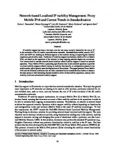
Fig. 7. (a) Buffer consumption rate and (b) Playback time with respect to the L2 handoff latency where the BH is 330 packets (33 frames).
4
Simulation Results and Discussion
The simulation was based on the Network Simulator (NS-2). Fig. 6 shows the simulation scenario and parameters. Under the rate shaping option, the STP is main variable to calculate the BT arget . In Eq. (1), the Tf old is selected as the STP in our simulation. Thus, L2 handoff latency (tL2 ) is a main control variable to calculate the BT arget . The L2 handoff latencies of each ARs are configured variously between 0.5 and 1.5 seconds. The IEEE 802.11b PHY is operated with 11Mbps in normal condition. However, it changes the mode to 1Mbps in the PAR before 0.5 seconds of handoff initiation. After the end of handoff, it continues 1Mbps data rate and the mode is changed to 11Mbps after 0.5 seconds later. In our simulation, the 10% additional margin is added to the BT arget . The maximum buffer limit is 10% bigger than the BT arget . Only the streaming traffic is emitted to the link, and other traffic are not introduced in the simulation, which makes queueing delay at ARs ignorable. Fig. 7(a) represents the buffer consumption ratio with respect to the L2 handoff latency variation under the BT arget is 330 packets(tL2 =1.0 seconds). The buffer drain rate is linearly increases according to the tL2 . When the tL2 is 1.5 seconds, 1.0 second, and 0.5 seconds, 330 packets, 326 packets, and 268 packets in the buffer are drained respectively. However, when the tL2 is 1.0s without the rate shaping, the whole packet, 330 packet, are consumed. The results are meet the result of the Eq. (8) well. The media playback time of a
146
D. Lee and J. Kim
streaming client is shown in Fig. 7(b) where the target buffer level is 330 packets and maximum buffer limit is 363 packets that is estimation result for 1 second of L2 handoff latency. When the L2 handoff latency is 1 second, the playback is not interrupted but continuously served. However, we can observe that playback is interrupted whenever a handoff happens under it’s L2 handoff latency is 1.5 seconds.
5
Conclusion
We introduced the seamless streaming framework by estimating the accurate buffer level for pre-buffering to compensate the handoff latency. We calculated the handoff latency in application point of view under the mobile IPv6 with fast handoff environment. The packet losses caused by decreased signal strength around handoff can be overcome by rate shaping controlled by client’s feedback information. Also, the fast handoff of mobile IPv6 reduces the handoff loss. Thus, the streaming application can only consider the STP to calculate the target buffer level. The simulation result shows that the handoff aware streaming has no playback discontinuity while keeps a minimal pre-buffer size. Acknowledgements. This work was supported by grant R05-2004-000-10987-0 from the Basic Research Program of the Korea Science & Engineering Foundation (KOSEF).
References 1. E. Steinbach, N. Farber, and B. Girod, “daptive playout for low latency video streaming,” in Proc. IEEE ICIP ‘01, 2001. 2. H. Yokota, A. Idoue, T. Hasegawa, and T. Kato, “Link layer assisted mobile IP fast handoff method over wireless LAN networks,” in Proc. ACM MobiCom ’02, Atlanta, Georgia, Sep. 2002 3. T. Zhang, J. C. Chen, and P. Agrawal, “Distributed soft handoff in all-IP woreless networks,” in Proc. of 3GWireless ’01, San Francisco, May 2001. 4. D. W. Lee and J. Kim, “Out-of-sequence packet analysis in mobile IP handoff and its enhancement,” in Proc. 3G Wirelesss ‘02, San Francisco, CA, May 2002. 5. D. Johnson and C. Perkins, “Mobility support in IPv6,” Internet Engineering Task Force, RFC 3344, Aug. 2002. 6. J. D. Pavon and S. Choi, ”Link adaptation strategy of IEEE 802.11 WLAN via received signal strength measurement ,” in Proc. IEEE ICC ‘03, 2003. 7. R. Koodli, “Fast handovers for mobile IPv6,” Internet Draft, Internet Engineering Task Force, March. 2003. 8. G. J. Conklin, et. al, “Video coding for streaming media delivery on the Internet,” IEEE Trans. on Circuits and Systems for Video Technology, vol. 11, no. 3, pp. 269-281, 2001.