Daniele Quercia and James Skene, for their help and suggestions in producing this work. References. 1. K. Arnold, B. O'Sullivan, R. W. Scheifler, J. Waldo, and ...
Building Adaptable Mobile Middleware Services Using Logical Mobility Techniques Stefanos Zachariadis, Manish Lad, Cecilia Mascolo, and Wolfgang Emmerich Department of Computer Science University College London Gower Street London WC1E 6BT United Kingdom {s.zachariadis|m.lad|c.mascolo|w.emmerich}@cs.ucl.ac.uk Summary. In recent years, various mobile middleware systems have been developed that build on top of the protocol stack provided by the underlying network operating system, to offer a set of higher level services. Common services provided include remote procedure calls, data sharing, service discovery etc. With the number of mobile devices, such as PDAs, mobile phones or smart phones increasing, as well as the impeding flourishing of embedded and wearable computing, the role of middleware in offering services that hide the complexity in the underlying environment is at the same time important and complex. The mobile environment is becoming highly dynamic, with very heterogeneous devices, in terms of both hardware and software, forming short lived ad hoc networks. In this chapter, we argue that the provision of static services cannot tackle the peculiarities of this environment. We present logical mobility as a technique for dynamic adaptation, detail a specification of a framework that offers its flexible use, and present a number of dynamic middleware services, which can be intelligently acquired by a device at runtime.
Key words: distributed objects, components, pervasive computing, model validation and analysis, process models
1 Introduction The further decentralisation of computing into increasingly inexpensive mobile devices, such as personal digital assistants, mobile phones, sensors and laptops, together with the advances in wireless networking (UMTS, 802.11, 802.15.4, 802.15.1 etc.), create a distributed computing environment that is becoming highly dynamic and heterogeneous. Developing applications in this environment is very difficult; Building directly on the operating system of a device and only having a networking
2
S. Zachariadis, M. Lad, C. Mascolo, W. Emmerich
protocol stack available to program against is particularly tedious and errorprone, as it forces the developer to handle directly the complexities of the environment, such as intermittent connectivity and heterogeneity. As such, multiple mobile computing middleware systems have been developed, that build on top of the operating system, hiding some of the complexities of the environment. Networked middleware systems build on the protocol stack to offer higher level services to applications. These services range from remote procedure calls to data sharing and service discovery. This has led to the development of various incompatible middleware systems, which are able to provide a fixed set of services. We argue that this approach does not adequately tackle the dynamicity of a mobile environment because the provision of fixed and static services cannot scale. The constant introduction of new devices into the network, which may offer different services, ranging from temperature sensing to printing, over different hardware, requires the middleware system to adapt or mutate to provide the functionality needed to allow an application to communicate with them. Pre-installing all the services that may be required before a device ships is not feasible, because mobile devices have strict memory limitations. Moreover, we argue that it is also very difficult to predict the services that may be needed throughout a device’s lifetime. In this chapter, we argue for offering logical mobility, or code relocation primitives as first class citizens in mobile middleware systems. The primitives can be used to built dynamic middleware services; in this context, a dynamic service is a service that can be dynamically deployed into a running system, or a service that can be changed at runtime. We discuss the utility of logical mobility for mobile systems and present the process algebra specification for a platform that allows systems to dynamically send, receive and deploy code. We then briefly present satin, a component based mobile computing middleware system, that encapsulates this platform, offering the flexible use of mobile computing paradigms to applications. We also show how this was used to build dynamic middleware services, ranging from advertising and discovery to ubiquitous security. The chapter continues as follows: Section 2 defines logical mobility and outlines its advantages for physically mobile systems. Section 3 details our logical mobility platform. Section 4 briefly outlines satin, and shows how the platform in Section 3 was instantiated. It concludes by presenting, as case studies, a number of mobile computing middleware services built and deployed. Section 5 gives a brief outline of related work, while Section 6 discusses and concludes the chapter.
2 Defining Logical Mobility Logical Mobility refers to the ability to change the configuration of the software of a distributed system, by transferring logical units between nodes. Logical
2 Defining Logical Mobility
Unit
Unit
Unit
3
Unit
Mobility Layer
Mobility Layer
Processing Environment
Processing Environment
Network Operating System
Network Operating System
Core Operating System
Core Operating System
Hardware
Hardware
Host A
Host B
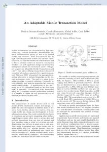
Fig. 1. A mobile code system, showing the transfer of a unit from Host B to Host A.
Mobility has been argued [20] to have great potential for engineering mobile systems, a potential that has not yet been realised. This section claims that logical mobility can be used as a technique that can adapt services, because it can encapsulate functionality which can be dynamically deployed onto a running system. Logical mobility is usually offered using Code Mobility techniques. In the following paragraphs, we define what code mobility is, outline its relationship to logical mobility and describe its usage paradigms. 2.1 Introduction to Code Mobility Code mobility has been defined [2] as ‘the capability to dynamically change the bindings between code fragments and the location where they are executed’. More informally, code mobility can be defined as the ability to move code between nodes in the network. It has been argued [5] that code mobility is a technology that can be used to engineer configurable, scalable and customisable large scale distributed systems, by allowing code to migrate and bind to different nodes of the running system. Mobile code systems usually define a code unit as a conceptual or realised abstraction that encapsulates a form of code. A code unit is the minimal unit of transfer or unit of mobility. Whereas code mobility specifically refers to the transfer of code between nodes, logical mobility builds on this notion and refers to the reconfiguration of systems by moving any part of the logical layer between nodes. Logical Mobility is usually offered using code mobility techniques to transfer information, including binary code, compiled for a specific architecture, interpreted textual scripts, bytecode compiled for a virtual platform, such as the Java Virtual Machine (JVM), but also application data such as profiles. In this context, data are defined to be anything that cannot be directly executed by the underlying platform. Figure 1, adapted from [15], shows an outline of two systems using mobile code. The core operating system is built on the hardware layer, and provides abstractions to access the hardware and basic services such as memory management. The networking aspects of the operating system are built on top
4
S. Zachariadis, M. Lad, C. Mascolo, W. Emmerich
of this; they provide basic networking services, such as a TCP/IP protocol stack. Layered on the network operating system is the Processing Environment (PE). The processing environment is a container which allows code units to run; it provides a set of primitives (the extent of which varies between platforms) to allow for code migration, or even for access to local resources. Any coordination between various units as well as between the units and the rest of the system happens at this layer. A Processing Environment usually acts as a sandbox, restricting the access of a unit to protect from malicious code. Figure 1 shows a unit transferred from one node to another. There are two manifestations of code mobility: weak mobility, where a code unit transfered cannot include execution state information and strong mobility, where this is possible. Strong mobility allows for a process or thread to suspend execution, move to another host and resume execution from the exact point at which it stopped on the originating host. At a conceptual level, the migration of a thread or process using a strong mobility mechanism can be completely hidden from the application programmer. A weak mobility mechanism can approximate the operation of a strong mobility one, provided that the application programmer is aware of the migration process; the programmer would need to explicitly save any data that are needed to resume execution at the recipient host before the transfer takes place and to use the data to resume appropriately after the transfer process is completed. By definition, weak mobility platforms consume less computational resources than strong mobility ones. 2.2 Paradigms of Code Mobility Usage of code mobility has been classified [5] into a set of paradigms: code on demand, remote evaluation, client server interactions and mobile agents. These paradigms mainly differ on the party that initiates transfer of code and on the party that actually transfers it. We extend these concepts to apply to Logical Mobility; As such, Client - Server (CS), a popular paradigm in traditional distributed systems, suggests the execution of some code in a computing device (the server) triggered by a request of another device (the client). The most common example of this paradigm are remote procedure calls (RPCs). Remote evaluation (REV) suggests that a host sends a particular unit to another host, to be executed there. This paradigm is employed by Distributed.NET [22] and other similar distributed computing environments, which work using the divide and conquer paradigm to break large computational challenges into smaller, more manageable problems and distribute those to machines around the world. The results are then sent back to the server orchestrating the problem, which can recompose the answer to the original challenge. The code on demand (COD) paradigm, enables a host to request a particular unit from another machine. Following the request, the code is transferred to the requesting host and can then be executed there. This is an example of dynamic code update, whereby a host or application can update
3 Conceptualising the Use of Logical Mobility over Physical Mobility
5
its libraries and available codebase at runtime. A mobile agent (MA), is an autonomous unit of code. It is injected into the network by a host, to perform some tasks on behalf of a user or an application. The agent can autonomously migrate from one execution environment to another. 2.3 Logical over Physical Mobility In previous work [24], we identified a number of examples showing that all paradigms of logical mobility can bring tangible benefits to mobile computing. The examples included dynamic updating in the face of limited resources, offering location-based services, active networking, exploiting distributed computational resources and limiting connectivity costs. Those benefits can be summarised in the following interrelated points: • • •
•
•
•
Logical mobility allows applications to update their codebase, hence acquiring new functionality. Logical mobility may permit interoperability with remote applications and environments, which have not been envisioned at design time. Logical mobility potentially achieves the efficient use of peer resources, as computationally expensive calculations can be offloaded to the environment. Logical mobility facilitates the efficient use of local resources, as infrequently used functionality can be removed to free some of the limited memory that mobile devices are equipped with. The functionality may potentially be retrieved later when needed. Logical Mobility primitives can be used to encapsulate, request and transfer functionality between nodes; hence it is a tool that can be used to create adaptable systems. By allowing functionality to be retrieved locally, Logical Mobility allows for autonomous operation instead of relying on an externally provided service.
3 Conceptualising the Use of Logical Mobility over Physical Mobility Having outlined the benefits of logical mobility for adaptable mobile computing systems, this section presents a conceptual object oriented framework for logical mobility targeting mobile systems. The system is general enough as to not be tied to any particular application or paradigm. The framework presented is built on the notion of weak mobility, because its implementation requires less resources than a strong mobility one. This section does not discuss in great detail the Client/Server paradigm defined above. Client/Server interactions are not directly beneficial for purposes of mobile adaptation, as they do not involve the transfer of functionality. This section will describe a conceptual platform for logical mobility, which
6
S. Zachariadis, M. Lad, C. Mascolo, W. Emmerich
Fig. 2. The Logical Mobility Unit.
will offer symmetric operation (the ability to both send and receive execution units), and will be engineered for the intricacies of physical mobility, taking into account, in particular, heterogeneity, security and limited resources. The platform describes is composed of various conceptual layers. The remainder of the section starts by describing a container that is used to encapsulate aspects of logical mobility; it then builds on that to define all the layers and aspects of the framework. 3.1 The Logical Mobility Unit Figure 2 presents a conceptual encapsulation of logical mobility as a Meta Object Facility [13]-compliant extension of the UML [12] meta model version 2.0. It builds upon and extends the concepts of Classifier, Class, InstanceSpecification and DataType. The diagram defines three aspects of Logical Mobility: Classes, ObjectSpecifications and DataTypes; DataTypes are defined as a bitstream that is not directly executable by the underlying architecture, and ObjectSpecifications are defined as specialisations of InstanceSpecifications that reify classes. As such, the framework specifically addresses the transfer of classes, instances and data as aspects of logical mobility. The Logical Mobility Entity (LME) is defined as an abstract generalisation of a Class, Instance or Data. Consequently, an instantiation of an LME represents an aspect of the logical layer of a system.
3 Conceptualising the Use of Logical Mobility over Physical Mobility
7
The Logical Mobility Unit (LMU) is defined as the minimal unit of transfer in this framework. An LMU is a container, that can encapsulate various constructs and representations of code and data. As such, an LMU is, in part, a composition of an arbitrary number of LMEs. This allows an LMU to contain anything from a single class to a collection of classes, instances and data. The LMU provides operations that permit inspection of contents. This allows a recipient to inspect an LMU before using it. The LMU can potentially encapsulate a Handler class. The Handler can be instantiated and the resulting object used by the recipient to deploy and manipulate the contents of the LMU. This can allow sender-customised deployment and binding. The Handler concept and name is taken from [17]. Handlers and deployment in general are further discussed in the next section. An LMU also encapsulates a set of attributes, called the properties of the LMU. An attribute is a tuple containing a key and a value and the properties of the LMU map each key to its associated value. As such, a reference to an attribute encapsulated in the LMU can be obtained by identifying its key. Attributes represent the metadata of the LMU. Attributes can be either mutable or immutable. The number and type of attributes is not fixed. The properties are used to describe the LMU they are associated with. For example, logical (software) or physical (hardware) dependencies, digital signatures and even end-user textual descriptions can be expressed as attributes. As such, they can be used to express the heterogeneity of the target environment. For example, an LMU that contains Java classes may specify that it requires a Java Virtual Machine that implements version 2 of the appropriate specification as an attribute. An ontology for attribute keys and values is not defined at this stage. Mutable attributes are useful because they allow for storing the state of the Logical Mobility Entities separately to their logic. This allows users, in principle, to update the logic of a logical mobility entity, while maintaining its state. This is useful in many scenarios; for example in self-updating mobile agents. The LMU and its contents can be serialised and deserialised. As such, the use of logical mobility techniques is equivalent to composing the LMU, serialising it, transferring it, deserialising it and deploying it, as well as triggering this sequence of operations. The next section describes a framework that allows this. 3.2 A Framework for Logical Mobility Figure 3 outlines a framework for the use of logical mobility techniques by mobile systems, as a collection of conceptual layers, built on top of the network operating system. The following paragraphs describe each layer in detail. The operations of the framework are modelled as a collection of interacting concurrent processes, using the Finite State Processes (FSP) process algebra [8], with each layer represented by a process. A process algebra was chosen over alternatives such as axiomatic and denotational models because of the algebra
8
S. Zachariadis, M. Lad, C. Mascolo, W. Emmerich
allows for a clear definition of the various states of each process and of the system as a whole. FSP was chosen in particular for reasons of familiarity, ease of use and tool support. The process algebra allows us to express safety and liveness properties on the framework, and verify that it operates correctly, while allowing callers to use any logical mobility paradigm. The process algebra specification for the platform follows: //Trust & Security Layer TRUSTANDSEC = ( inspect -> INSPECTION |examine -> EXAMINATION ), EXAMINATION = ( trusted -> TRUSTANDSEC |mistrusted -> TRUSTANDSEC ), INSPECTION = ( accepted -> TRUSTANDSEC |rejected-> TRUSTANDSEC ). //Serialisation & Desirialisation Engine SERDESERENGINE = ( deserialise -> DESERIALISING |serialise -> SERIALISING), DESERIALISING = ( deserialised -> CONFLICTCHECK |deserFailed -> SERDESERENGINE ), CONFLICTCHECK = ( conflict -> RESOLVECONFLICT |noConflict -> deserSuccess -> SERDESERENGINE ), RESOLVECONFLICT = ( deserReject -> deserFailed -> SERDESERENGINE |conflictResolved -> deserSuccess -> SERDESERENGINE ), SERIALISING = ( serSuccess -> SERDESERENGINE |serFailed -> SERDESERENGINE ). //Communications Layer CONTROLLER = ( controllerStart -> ON ), ON = ( sendRequest -> ON |receiveRequest -> REQUESTRECEIVED |controllerStop -> CONTROLLER ), REQUESTRECEIVED = ( acceptRequest -> ON |rejectRequest -> ON). SENDERRECEIVERCONTROL = ( srStart -> ON ), ON = ( receiveLMU -> ON |sendLMU -> ON |srStop -> SENDERRECEIVERCONTROL ). RECEIVER = ( receiveLMU -> deserialise -> DESERIALISATION |srStop -> RECEIVER ), DESERIALISATION = ( deserSuccess -> inspect -> INSPECTION |deserFailed -> RECEIVER ), INSPECTION = ( accepted -> deployLMU -> deployed -> RECEIVER |rejected -> RECEIVER ). SENDER = ( sendLMU -> examine -> EXAMINATION |srStop -> SENDER ), EXAMINATION = ( trusted -> serialise -> SERIALISING |mistrusted -> SENDER ), SERIALISING = ( serSuccess -> lmuSend -> SENDER |serFailed -> SENDER ). ||SENDERRECEIVER = ( SENDERRECEIVERCONTROL || SENDER || RECEIVER ).
||API = ( SENDERRECEIVERCONTROL || SENDER || RECEIVER || TRUSTANDSEC || SERDESERENGINE ||CONTROLLER). //APPLICATION APPLICATION = ( deployLMU -> DEPLOYLMU ), DEPLOYLMU = ( lmuPartialAccept -> deployed -> APPLICATION |lmuAccept -> deployed -> APPLICATION |lmuInstantiateHandler -> deployed -> APPLICATION |lmureject -> deployed -> APPLICATION ). //Safety and Liveness Properties
3 Conceptualising the Use of Logical Mobility over Physical Mobility property property property property progress progress
9
SERIALISETRUSTED = ( trusted -> serialise -> SERIALISETRUSTED ). SENDSERIALISED = ( serSuccess -> lmuSend -> SENDSERIALISED ). INSPECTDESERIALISED = ( deserSuccess -> inspect ->INSPECTDESERIALISED ). DEPLOYACCEPTED = ( accepted -> deployLMU -> DEPLOYACCEPTED ). SENDANDRECEIVELMUS = { sendLMU, receiveLMU } SENDANDRECEIVEREQUESTS = { sendRequest, sendRequest }
//Framework ||FRAMEWORK = ( SENDERRECEIVERCONTROL || SENDER || RECEIVER || TRUSTANDSEC || SERDESERENGINE || CONTROLLER || APPLICATION || SERIALISETRUSTED || SENDSERIALISED || INSPECTDESERIALISED || DEPLOYACCEPTED ). )
Application API Communications Trust & Security
Serialisation/Deserialisation Engine
Controller
Sender/Receiver
Transport
Fig. 3. A Logical Mobility Framework.
The specification is discussed in the following paragraphs. The Trust & Security Layer. There are many aspects to consider when trying to establish a secure mobile computing environment that uses logical mobility. In particular, privacy of communications, system integrity against malicious LMUs and trust should be calculated and maintained between the various nodes. System integrity and trust are the responsibility of the trust & security layer, of which there can be various realisations that employ different trust models, digital signatures and trusted third party-based verifications, heuristic virus scanning, or even logic based techniques such as proof carrying code [10] to offer various levels of security. It is represented as the TRUSTANDSEC process, which may either inspect an incoming LMU (thus trying to maintain system integrity) or examine the host to which an LMU is to be sent (thus implementing a trust mechanism). The result of the inspection (represented by INSPECTION) is either accepted, which denotes that the LMU is not malicious and that it behaves as advertised, or rejected otherwise. The result of the examination (represented by EXAMINATION) is either trusted, or mistrusted. The exact semantics of accepted, rejected, trusted and mistrusted depend on the particular realisation. The Serialisation & Deserialisation Engine. The serialisation & deserialisation engine is responsible for converting an LMU into a bitstream and vice versa. Different implementations may use different encodings to write and read the stream. When deserialising a bitstream,
10
S. Zachariadis, M. Lad, C. Mascolo, W. Emmerich
the engine is responsible for instantiating an LMU with the contents of the bitstream into a processing environment where it can be inspected by the trust & security layer. Deserialisation may fail if an element in the LMU has references which cannot be restored in the recipient node or if, because of a failure in the transport layer, the bitstream was not successfully received. Upon deserialisation, the elements of the LMU are checked for conflicts with elements already in the system. Essentially, conflicts may occur if elements of the LMU define themselves using names that are already in use in the recipient node. If a conflict is detected, implementations of the serialisation & deserialisation engine may either reject the LMU, or try to resolve the conflict, by loading it, for example, into a private namespace. The layer is represented by process SERDESERENGINE. The process can either deserialise an incoming LMU or serialise an outgoing one. In the former scenario, represented by DESERIALISING, the process can either fail (deserFailed), if, for example, the incoming bitstream was invalid (due to a transport layer failure) and could not be read or references contained in the LMU could not be restored, or succeed (deserialised). In the latter case, the serialisation & deserialisation engine checks whether the contents of the LMU conflict with the running system (CONFLICTCHECK). If a conflict is not detected (noConflict), then the deserialisation process is successfully completed (deserSuccess). If a conflict is detected, then the engine may try to resolve it (RESOLVECONFLICT), by, for example, loading the contents in a private namespace. If the conflict resolution process is successful (conflictResolved), then the deserialisation process is successfully completed (deserSuccess). Otherwise, the LMU is rejected (deserReject) and the deserialisation process fails (deserFailed). When serialising an outgoing LMU (SERIALISING), the process may either successfully complete (serSuccess) or fail (serFailed). A reason for failure is, for instance, that the contents of the LMU contained non serialisable references, such as a reference to a hardware resource that does not exist on the recipient host. The Communications Layer. The communications layer builds on the basic primitives provided by the transport layer for sending and receiving LMUs. In particular, it is composed of two different modules, the controller and the sender - receiver, both of which are described below. The controller implements an application layer Client/Server protocol that allows hosts to request the composition and transfer of a particular LMU from a remote host. The protocol encapsulating the request is considered to be specific to the implementation, but it is expected that the request message will be based on LMU attributes. Thus, the controller allows remote hosts to pull logical mobility units. Note that the protocol implemented by the controller is asynchronous; a request is non blocking and an LMU requested may be retrieved at a later stage. Moreover, a request that has been denied simply results in the requested LMU not being sent - no other information is generated and the requesting host is not notified of the failure.
3 Conceptualising the Use of Logical Mobility over Physical Mobility
11
This chapter considers potential failure to be typical of the dynamicity of a mobile distributed system - as such, failure is not an exception, rather it is a frequent event that the application programmer (or a middleware system built around this framework) must be aware of. In the process algebra specification, the controller, represented by process CONTROLLER, is not active initially - this means that no requests can be sent or received. The controller can be activated (controllerStart) and an active controller (ON) can receive a request (receiveRequest), send a request (sendRequest) or be deactivated (controllerStop). Notice that this implies that application programmers using this framework should be made explicitly aware of the fact that their requests may fail and that no reply is expected when sending a request, as explained above. When a request is received (REQUESTRECEIVED), it can be either rejected (rejectRequest) or accepted (acceptRequest). An accepted request implies that an LMU will be composed and sent (sendLMU in the sender - receiver - see below). Note that failures in the transport layer may result in a request not being successfully sent or received. Realisations of the framework may notify the caller about these failures. The Sender - Receiver. Using the infrastructure provided by the serialisation & deserialisation engine and the trust & security layer, the sender - receiver allows for sending and receiving LMUs. In the process algebra specification the Sender - Receiver is modeled as process SENDERRECEIVER. SENDERRECEIVER is modelled as a concurrent composition of processes SENDER, RECEIVER and SENDERRECEIVERCONTROL. The latter is responsible for enabling and disabling the functionality of sending and receiving LMUs, while SENDER and RECEIVER are responsible for sending and receiving LMUs, respectively. The sender - receiver is inactive initially, meaning that no LMUs can be sent or received. It can be activated (srStart), and an active sender - receiver (ON) can receive an LMU (receiveLMU), send an LMU (sendLMU) or be deactivated (srStop). When receiving an LMU, the serialisation & deserialisation engine is used to deserialise the incoming bitstream into an LMU. The deserialisation process (DESERIALISATION), can either succeed (deserSuccess) or fail (deserFailed). In the former scenario, the sender - receiver uses the trust & security layer to inspect the deserialised LMU (INSPECTION) for malicious elements. This can either result in rejecting the LMU (rejected), or accepting it (accepted) and passing it to the application for deployment (deployLMU). When sending an LMU (sendLMU) the recipient host is first examined (examine) by the trust & security layer, to see whether the local host trusts it to send it information. The result of this process (EXAMINATION), is that the host is either trusted or mistrusted. If the host is trusted, then the serialisation & deserialisation engine attempts to serialise the LMU. As mentioned above,the serialisation process (SERIALISING) can either result in success (serSuccess), allowing the LMU to be sent (lmuSend), or in failure (serFailed). Note that failures in the transport layer may result in the LMU not being successfully sent or received. In this case, the deserialisation process in the receiving host, as performed by the serialisation and deserialisation engine,
12
S. Zachariadis, M. Lad, C. Mascolo, W. Emmerich
Fig. 4. A state machine representing the Sender.
Fig. 5. A state machine representing the Receiver.
will fail. SENDER and RECEIVER are visualised as state machines in Fig. 4 and 5 respectively. Note that LMUs can be sent independently of the controller - i.e. an LMU can be sent without the host having requested it. The recipient does, however, have the option of rejecting an incoming LMU. As such, when modelled as concurrent processes, the sendLMU action is available independently of whether a request has been received and accepted. This allows for the operation of the Mobile Agent and Remote Evaluation paradigms, as will be shown in Section 3.3. Both the controller and the sender - receiver can be realised as concurrent threads which can be started and stopped by the Application Programmer Interface. By allowing this to happen, we allow implementations to stop monitoring for requests, conserving resources, such as battery, and catering for the eventuality of network disconnection. The Application Programmers Interface. The Application Programmers Interface (API) builds on the functionality provided by the lower layers and provides primitives that an application can use to create and send an LMU, to request an LMU to be received as well as to start and stop the controller and the sender - receiver. Algebraically, the functionality exposed by the API can be represented as a concurrent composition of the above.
3 Conceptualising the Use of Logical Mobility over Physical Mobility
13
The Application Layer. Applications built using this framework are part of the application layer. When the communication layer receives an LMU which is successfully deserialised and inspected, it passes it on to an application for deployment. Note that, in this context, an application may represent any software abstraction that uses this framework for logical mobility; as such, applications can range from end-user applications to aspects of the system. In the specification, an Application deploying an LMU is modeled by process APPLICATION. When an LMU is passed to an application for deployment (deployLMU), it is inspected (shown in DEPLOYLMU). The results of the inspection can be the following: • • •
•
Partial Acceptance. Some aspects of the LMU are accepted, while others are rejected. This is represented by lmuPartialAccept. Full Acceptance. All the contents of the LMU are accepted by the application. This is represented by lmuAccept. Instantiation of the Handler. The application may not know how to deploy the LMU received. If the LMU contains a Handler, then the latter can be instantiated to take care of the deployment. This is represented by lmuInstantiateHandler. Rejection. The LMU may also be rejected by the application. There can be many reasons for this - the application may, for example, have no need for the contents of the LMU. This is represented by lmuReject.
SERIALISETRUSTED, SENDSERIALISED, INSPECTDESERIALISED, DEPLOYACCEPTED are the safety properties for this framework. In particular, the safety and liveness properties for the platform state the following: •
SERIALISETRUSTED is a safety property that ensures that an LMU will only be serialised to be sent (action serialise) if the recipient host is trusted (action trusted) to receive it. • SENDSERIALISED is a safety property that ensures that an LMU will only be sent (action lmuSend) if it has been successfully serialised (action serSuccess). • INSPECTDESERIALISED is a safety property that ensures that an LMU will only be inspected for security reasons (action inspect) if it has been successfully deserialised (action deserSuccess). • DEPLOYACCEPTED is a safety property that ensures that an LMU will only be deployed (action deployLMU) if it is accepted (action accepted) by the inspection process. • SENDANDRECEIVELMUS is a liveness property that ensures that, given an infinite length of time, the framework will be able to send and receive an infinite number of LMUs (actions sendLMU and receiveLMU), avoiding deadlocks. In other words, that both sending and receiving will happen an infinite number of times.
14
•
S. Zachariadis, M. Lad, C. Mascolo, W. Emmerich
SENDANDRECEIVEREQUESTS is a liveness property that ensures that, given an infinite length of time, the framework will be able to send and receive an infinite number of requests for LMUs (actions sendRequest and receiveRequest), avoid deadlocks.
The framework was found to satisfy all safety and liveness properties, by using the FSP model checking tool, LTSA [8]. The next section describes the framework and shows how it can be used to offer all the paradigms discussed in 2.2. 3.3 Transferring Logical Mobility Units The following paragraphs demonstrate the generality and applicability of this framework, by showing how it can be used by applications to employ the logical mobility paradigms outlined in Section 2.2. In particular, this section shows how Code On Demand, Remote Evaluation and Mobile Agents can be mapped onto a sequence of actions on the model of the framework. To illustrate this, two instances of the framework, A & B, are composed. The composition is as follows: ||TWOINSTANCES = ( a:FRAMEWORK || b:FRAMEWORK ) /{a.sendRequest/b.receiveRequest, a.receiveLMU/b.lmuSend, b.sendRequest/a.receiveRequest, b.receiveLMU/a.lmuSend}.
The / notation renames actions. This results, for example, in b.receiveRequest to be renamed to a.sendRequest. This results in modelling that when A sends a request, B receives it. Code On Demand The use of Code on Demand is equivalent to sending a request via the controller and getting the code requested by the sender - receiver. In the following trace, node A requests and receives an LMU from node B:
3 Conceptualising the Use of Logical Mobility over Physical Mobility
15
Step Number Action 0 a.srStart 1 a.controllerStart 2 b.srStart 3 b.controllerStart 4 a.sendRequest 5 b.acceptRequest 6 b.sendLMU 7 b.examine 8 9 10 11 12 13 14 15 16 17 18 19 20 21
Description starts the sender - receiver on node A starts the controller on node A starts the sender - receiver on node B starts the controller on node B A sends a request for the code required B accepts the request B packs and tries to send the LMU B inspects the target node (A) to see whether it is trusted b.trusted B finds that A is trusted b.serialise B tries to serialise the LMU b.serSuccess B successfully serialises the LMU a.receiveLMU B sends the LMU / A receives it a.deserialise A deserialises the LMU a.deserialised the LMU is deserialised and checked for conflicts a.conflict a conflict is detected a.conflictResolved conflict is resolved a.deserSuccess deserialisation process is successfully completed a.inspect LMU is inspected for security a.accepted it is accepted into the system a.deployLMU LMU is passed on to the application for deployment a.lmuAccept the application fully accepts it a.deployed LMU is successfully deployed on A
Remote Evaluation The use of Remote Evaluation is equivalent to sending the LMU via the sender - receiver. The recipient host may decline the LMU. In the following trace, node A sends an LMU to node B. Step Number Action 0 a.srStart 1 b.srStart 2 a.sendLMU 3 a.examine 4 5 6 7 8 9 10 11 12 13 14 15 16
Description starts the sender - receiver on node A starts the sender - receiver on node B A packs and tries to send the LMU to B A inspects the target node (B) to see whether it is trusted a.trusted A finds that B is trusted a.serialise A tries to serialise the LMU a.serSuccess A successfully serialises the LMU b.receiveLMU A sends the LMU / B receives it b.deserialise B deserialises the LMU b.deserialised the LMU is deserialised and checked for conflicts b.noConflict no conflict was found b.deserSuccess deserialisation process is successfully completed b.inspect LMU is inspected for security b.accepted it is accepted into the system b.deployLMU LMU is passed on to the application for deployment b.lmuPartialAccept the application partially accepts it (i.e. parts of the LMU are discarded) b.deployed the LMU is successfully deployed on B
Note that this framework does not directly address the issue that an application using Remote Evaluation may request a reply based on the execution of the LMU sent. The request may be stored in the properties of the LMU. The reply sent is considered to be an application level issue.
16
S. Zachariadis, M. Lad, C. Mascolo, W. Emmerich
Mobile Agents The use of Mobile Agents is equivalent to sending an LMU with a Handler, responsible for activating a thread representing the agent on the recipient host. In the following trace, node A sends an agent to node B. Step Number Action 0 a.srStart 1 b.srStart 2 a.sendLMU 3 a.examine 4 5 6 7 8 9 10 11 12 13 14 15 16 17
Description starts the sender - receiver on node A starts the sender - receiver on node B A packs and tries to send the LMU to B A inspects the target node (B) to see whether it is trusted a.trusted A finds that B is trusted a.serialise A tries to serialise the LMU a.serSuccess A successfully serialises the LMU b.receiveLMU A sends the LMU / B receives it b.deserialise B deserialises the LMU b.deserialised the LMU is deserialised and checked for conflicts b.noConflict no conflict was found b.deserSuccess deserialisation process is successfully completed b.inspect LMU is inspected for security b.accepted it is accepted into the system b.deployLMU LMU is passed on to the application for deployment b.lmuInstantiateHandler application instantiates the handler of the LMU b.deployed the LMU is successfully deployed on B handler starts a thread representing the agent.
The agent can then use the API of the framework to migrate itself to another host. It is important to note that the framework offers the ability to reject an incoming LMU at many different stages. As such, an LMU can be rejected if deserialisation fails, if it is malicious, or if it creates an unresolvable conflict in the system. Moreover, finer-grained control is given to the application programmer, who may inspect the contents of the LMU before accepting it or rejecting it, partially or fully. Similarly, the process of sending an LMU can fail on two stages: if the target host is not trusted or if the serialisation process fails. Finally, realisations of the serialisation & deserialisation engine may decline serialising an LMU if it contains data that should not be shared (for legal reasons, for example) or cannot be shared (as the data can contain non serialisable elements).
4 Logical Mobility for Mobile Computing Middleware This section starts by outlining a middleware system that we have developed, which makes use of the logical mobility platform described above. It then proceeds by describing a number of services that were built using it.
4 Logical Mobility for Mobile Computing Middleware
17
4.1 The satin Component Metamodel and Middleware System In order to engineer a mobile computing system to take advantage of the logical mobility platform described above, we designed the satin component metamodel, which we instantiated as the satin middleware system. The metamodel is described in [25] in detail, and is outlined in the following paragraph. satin is a local component model, where components reside in the same address space and are interconnected using local references. A satin component encapsulates functionality, from user interfaces and libraries, to protocol stacks. A component offers functionality through well defined interfaces, called facets. Components can have arbitrary metadata attached; satin allows for dynamically querying the local system as to what components are available, and provides support for late binding of components. Moreover, the satin metamodel provides for the first class use of logical mobility primitives, allowing instances to send and receive components dynamically. This is abstracted in the metamodel by a Deployer component. Finally, satin provides an event mechanism, that allows listeners to be notified of changes in component availability. The platform described above was implemented in MiToolkit [7], and was used by satin as a library to send and receive Java-based LMUs. The implementations of satin and MiToolkit require 150329 bytes in total, and are written in Java 2 Micro Edition (Connected Device Configuration / Personal Profile). satin and MiToolkit enabled us to build a number of middleware services, which are outlined below. 4.2 A Dynamic Advertising and Discovery Framework One of the fundamental services of mobile computing middleware systems, is the ability to reason about the environment. The environment is defined as the network of devices that can, at a specific point in time, communicate with each other. The devices can be both mobile and stationary - with the presence of mobile devices, however, the environment can be rapidly changing. In order to adapt, a mobile system needs to be able to detect changes to its environment. As the device itself is also part of that environment, it also needs to advertise its presence. A mobile device, however, may be able to connect to different types of networks, either concurrently or at different times, with different networking interfaces. There also are many different ways to do advertising and discovery. Imposing a particular advertisement and discovery mechanism can hinder interoperability with other systems, making assumptions about the network, the nodes and environment, which may be violated at some later stage or simply not be optimal in a future setting - something which is likely to happen, given the dynamicity of the target area of this chapter. From the point of view of satin, the ability to reason about the environment is translated into the ability to discover components currently in reach and to advertise the components installed in the local system. This is achieved
18
S. Zachariadis, M. Lad, C. Mascolo, W. Emmerich
via the use of Remote and Discovery components, as well as Advertiser, Advertisable, DiscoveryFacet and ComponentListener facets. This is described in detail bellow. Components that wish to advertise their presence in the environment must implement the Advertisable facet. Examples of advertisable components include codec repositories, file transfer services or sensing capabilities. The Advertisable facet exports a method that returns a message that is used for advertising; thus, the advertising message allows the Advertisable component to express information that it requires advertised. An advertising technique is represented by an Advertiser component, which is a component implementing the Advertiser facet. An advertiser component is responsible for accepting the message of advertisable components, potentially transforming it into another format and using it to advertise them. An advertiser allows components that wish to be advertised to register for advertising. The combination of component availability notification and advertiser registration, allows an advertisable component to register to be notified when specific advertisers are added to the system. The advertisable component can then register to be advertised by them. Moreover, an advertisable component can express that it requires a particular advertiser in its dependencies. Thus, the semantics of the advertisable message are not defined and depend on the advertisable component and on the advertising technique (i.e., the advertiser component) used. Note that a component can implement both the Advertiser and the Advertisable facets. This allows for the advertising of advertising techniques; in this way, for example, the existence of a multicast advertising group can be advertised using a broadcast advertiser. Combined with the use of logical mobility primitives, this allows a host to dynamically acquire a different advertising and discovery mechanism, for a network that was just detected. For example, upon approaching a Jini network [23], a node can request and download the components that are needed to advertise to, and use functionality from, the network. Similarly, discovery techniques are encapsulated by Discovery Components, which implement the DiscoveryFacet facet. There can be any number of discovery components installed in a system. A discovery component acts as registry of advertisable components located remotely. The middleware system defines the RemoteComponent. It is used to represent components, which have been found remotely. A remote component is an immutable component that cannot directly export any functionality to local components. It only exports methods needed to access its properties, location and advertising message. Hence, Discovery Components act as a collector of Remote component references, which can be added and removed dynamically, as they are discovered. Discovery components emit events representing the availability of remote components. Local components can register a ComponentListener with a discovery component, to be notified when components satisfying a given set of attributes are located. ComponentListener is represented as a satin facet. The advertising and discovery framework allows for Remote Components, to
4 Logical Mobility for Mobile Computing Middleware S
E
I
N
I
T
A
T S
t
a
t
u
e
c
h
n
o
l
o
g
y
S
e
l
e
c
t
o
t
e
r
n
a
l
T
r
u
s
r
u
s
t
&
N
e
g
o
t
i
a
t
i
o
f
o
r
m
a
t
i
o
a
e
m
o
S
e
c
h
n
o
A
T
I
o
l
i
c
y
W
a
r
e
h
o
u
s
i
s
c
o
v
e
r
o
l
i
c
i
e
P
o
e
l
c
i
i
c
W
D
y
n
a
m
i
o
A
T
e
p
I
e
n
n
f
f
i
o
o
i
i
n
o
v
g
i
c
u
r
o
m
a
a
n
a
r
e
g
o
t
i
t
i
o
e
n
t
a
t
i
o
o
l
i
c
y
&
S
e
s
s
i
o
n
M
a
n
a
g
e
o
e
n
t
s
a
t
o
r
n
f
o
o
l
r
e
t
m
N
F
e
x
o
O
i
c
c
y
e
o
m
i
e
n
n
t
t
r
n
C
T
I
O
N
t
E
C
I
S
I
O
N
n
R
M
A
T
I
O
n
o
f
o
n
r
t
r
m
a
o
l
t
i
o
n
N
n
v
i
r
o
n
m
e
n
t
a
l
R
i
N
n
l
E
t
r
n
C
m
e
n
I
I
a
e
e
r
D
n
p
t
A
C
D
m
p
N
y
I
o
P
r
o
T
p
P
o
P
o
I
l
A
m
E
D
r
a
c
C
o
r
y
s
N
P
i
n
s
D
f
o
y
S
v
i
e
C
P
n
t
N
D
I
a
n
D
n
c
n
P
E
i
n
S
n
l
t
D
I
p
r
T
x
p
s
T
E
19
e
s
t
o
f
S
t
a
c
k
n
D
a
t
a
Fig. 6. The SEINIT architecture
be requested and deployed locally. Moreover, the logical mobility functionality encapsulated by satin, allows the framework and instantiations of the framework to be dynamically deployed and used. The framework itself requires 6668 bytes. We have implemented a centralised publish discovery and a multicast implementation of the framework. Those require 22797 and 22161 bytes, respectively. 4.3 A Dynamic Pervasive Security Framework The IST-funded SEINIT project [21] focused on the area of pervasive computing security. It involved the development of a trusted and dependable security framework that could operate across multiple devices and heterogeneous networks. The main challenges were to provide an environment within which users could communicate securely while moving through multiple different security domains, without having to worry about continually keeping track of their changing environmental context. The aim of the project was to design an architecture that abstracts away from the low-level technology-specific security configuration. Users are able to define security policies per domain. The system is responsible for translating a policy to a concrete technology and using it to transparently maintain the appropriate level of security per domain. Figure 6 provides a high-level illustration of the overall SEINIT architecture. The SEINIT middleware is composed of three main building blocks: Information, Decision and Action. Any information that is gathered and stored
20
S. Zachariadis, M. Lad, C. Mascolo, W. Emmerich
within the Information module (such as trust status, user policies, dynamic environmental context and device configuration), is then analysed and processed within the Decision module. This generates and establishes the necessary security policy and configuration ready for enforcement. The Action module is responsible for invoking the appropriate functionality required to enforce the relevant policies. As users move through different security domains, they may find themselves connected to a security domain that is either untrusted, or in which some malicious activity is suddenly detected. At this stage, security renegotiation takes place automatically, to ensure that communication remains appropriately secured to the level defined in the security policies. However, this inevitably means that users may find themselves unable to communicate securely unless they have a specific security technology’s functionality available on their devices (e.g. IPSec configuration). To overcome this situation, SEINIT defines a class of code units called TechnoWrappers (Technology Wrapper). Each TechnoWrapper encapsulates the functionality and configuration required for invoking a specific security technology. A TechnoWrapper is defined as a satin component that implements the Advertisable facet. Once security re-negotiation has determined the specific technology required to secure the user’s communication through a given security domain, the satin Discovery process is used during decision-making, to discover and request the appropriate TechnoWrapper code unit from a satin advertising server. On retrieval, action is taken by the satin Deployer to fetch and deploy the appropriate TechnoWrapper code unit ready for invocation of its functionality. Each TechnoWrapper code unit encapsulates into an LMU both its own code, and the data that it requires. This LMU is then transferred to the user’s local device. On receipt of the LMU, the operations that permit inspection of an LMU’s contents are used to extract the TechnoWrapper code, instantiate it, and initialise it with the appropriate data ready for use on the user’s local device. The SEINIT TechnoWrapper code unit hierarchy consists of an abstract class TechnoWrapper, written in 315 physical source lines of code and containing functionality to encapsulate common data files into an LMU for transfer, undertake common policy transformations, and initiate basic activation of the security technology. The subclasses TechnoWrapperIPSec and TechnoWrapperPANA are defined, written in 78 physical source lines of code. These contain specialised functionality to encapsulate the TechnoWrapper code and any technology-specific data files into the LMU for transfer. The transfer has been noted to occur in the order of tenths of a second across a local-area network. The use of satin in SEINIT shows the suitability of logical mobility techniques in the security domain - in particular, as mobile devices cannot have all the code needed to communicate securely in every possible security domain,
4 Logical Mobility for Mobile Computing Middleware
21
logical mobility techniques and satin in particular are used to discover and download the code when needed. 4.4 Miscellaneous Services We conclude this section by showing how two smaller scale dynamically deployable services built: a scripting service, and a service allowing the deployment of system (i.e. native) software packages. The satin Scripting Framework BeanShell [11], an open source Java source interpreter and scripting mechanism, was adapted to run as a satin component. This allows satin components to use scripts and to be scripted. A “Shell” application was created for satin using the BeanShell, which allows developers to manipulate the container and its contents by typing Java statements at runtime. The Shell component and BeanShell encapsulation require 10,028 bytes. Logical Mobility Units can be used to dynamically deploy both the scripting framework and scripts. System Package Management In ongoing work to use satin in a programmable active networking project, we required the ability to interface with the underlying operating system, and in particular with the local package manager. In particular, we needed to create satin components that used system software to do intelligent packet dropping (using netfilter/IPTables) and media transcoding (using VideoLAN). The idea behind the project, is that if there is not enough bandwidth, active networking satin components will be deployed to routing nodes in the network and either drop packets, or dynamically transcode a media stream to a lower bitrate. As such, we needed the ability to express dependencies on system packages and to dynamically ship and deploy them. Hence, we needed to interface with the underlying package manager. Using the DataType LME specialisation, we encapsulated RPM packages into LMUs. We created RPMPackageManager as a component that tries to install any RPM packages included in an incoming LMU to the underlying system. It can also query the RPM database on the existence of particular packages. RPMPackageManager was written in 135 physical source lines of code, and exports functionality through an 8 line facet. Using it, we can send, receive and deploy RPM packages through the code mobility service. Moreover, the RPMPackageManager itself can be sent and received dynamically.
22
S. Zachariadis, M. Lad, C. Mascolo, W. Emmerich
5 Related Work This section briefly discusses related approaches in conceptualising logical mobility and critically outlines mobile middleware systems that employ its use. [5] provides a conceptual framework for reasoning about code mobility, on which this chapter is based. The paper discusses code mobility and its applications, defines a mobile code system, as shown in Fig. 1, and examines the paradigms of code mobility as discussed in Section 2.2. It also provides a survey of mobile code toolkits and outlines some application domains for the use of mobile code. There has also been research in evaluating the performance of logical mobility. [6] describe a UML-based methodology for performance analysis of logically mobile software architectures. UML sequence and collaboration diagrams, are annotated with mobility-related stereotypes, allowing the developer to model the code migration aspects of the system. The diagrams are then annotated with probabilities and cost information, and a performance model of the application is obtained, allowing the designer to evaluate the choices made. In [16], the notion of location in a Mobile Unity [19] program is used to model the various paradigms of transferring of code between nodes. Although similar to what presented in this chapter, the main difference the described the transfer of code, rather than the framework required to transfer it. µCode [14] is a lightweight Java library which provides a minimal set of primitives allowing code mobility. The framework presented in this chapter shares µCode’s objective to offer a very lightweight set of primitives to support code mobility. Its non-obtrusiveness allows it to be easily integrated with various middleware systems, and its small footprint makes it suitable for mobile middleware. The framework described in this chapter differes in that it is modular, with each module modeled, and addresses concerns of heterogeneity through the use of metadata. There have also been a number of mobile middleware systems, that employ some logical mobility techniques. The difference with our system is that it is more general; other approaches offer the use of particular paradigms to solve problems which are limited in scope, while others only use logical mobility internally, hiding it from the application developer. Examples include Lime[9], where mobile agents are used to share data, PeerWare[4], where remote evaluation is used to perform operations on remote data sites and Jini[1], where code on demand is used to offer services.
6 Conclusions This chapter argued for the utility of adaptable mobile middleware services, which can be dynamically deployed into a running system. Logical mobility was presented as a technique for adaptation, its advantages for physical mobility were outlined, and a conceptual framework that allows its flexible use by mobile systems was detailed. The instantiation of this framework in the satin middleware system was described, and its suitability was demonstrated,
References
23
by illustrating a number of dynamically deployable services that were built using it. We are currently experimenting on using aspects of this framework in the RUNES project [3], which would allow RUNES middleware instances to dynamically adapt. Furthermore, we are currently porting the framework to motes, using the Contiki operating system. Mitoolkit, satin and a number of applications have been released as open source at [18]. Acknowledgments The authors would like to thank Stephen Hailes, Peter Kirstein, Daniele Quercia and James Skene, for their help and suggestions in producing this work.
References 1. K. Arnold, B. O’Sullivan, R. W. Scheifler, J. Waldo, and A. Wollrath. The Jini[tm] Specification. Addison-Wesley, 1999. 2. Antonio Carzaniga, Gian Pietro Picco, and Giovanni Vigna. Designing Distributed Applications with Mobile Code Paradigms. In Proceedings of the 19th International Conference on Software Engineering, pages 22–32, Boston, MA, 1997. ACM Press. 3. P. Costa, G. Coulson, C. Mascolo, G. P. Picco, and S. Zachariadis. The RUNES middleware: A reconfigurable component-based approach to networked embedded systems. In 16th IEEE International Symposium on Personal Indoor and Mobile Radio Communications (PIMRC05), Berlin, Germany, September 2005. IEEE. 4. G. Cugola and G. Picco. Peer-to-Peer for Collaborative Applications. In Proceedings of the IEEE International Workshop on Mobile Teamwork Support, Collocated with ICDCS’02, pages 359–364, July 2002. 5. A. Fuggetta, G. Picco, and G. Vigna. Understanding Code Mobility. IEEE Transactions on Software Engineering, 24(5):342–361, May 1998. 6. V. Grassi and R. Mirandola. PRIMAmob-UML: a Methodology for Performance Analysis of Mobile Software Architectures. In Proceedings of the 3rd International Workshop on Software and Performance (WOSP-02), pages 262–274, New York, July 2002. ACM Press. 7. M. Ijaha. Mitoolkit. Master’s thesis, University College London, United Kingdom, 2004. 8. J. Magee and J. Kramer. Concurrency: Models and Programs - From Finite State Models to Java Programs. John Wiley, 1999. 9. A. Murphy, G. Picco, and G.-C. Roman. Lime: A Middleware for Physical and Logical Mobility. In Proceedings of the 21st International Conference on Distributed Computing Systems (ICDCS-01), pages 524–536, Los Alamitos, CA, April 16–19 2001. IEEE Computer Society. 10. G. C. Necula. Proof-carrying code. In The 24TH ACM SIGPLAN-SIGACT Symposium on Principles of Programming Languages, pages 106–119. ACM SIGACT and SIGPLAN, ACM Press, January 1997. 11. P. Niemeyer. BeanShell - Lightweight Scripting for Java, 1997. 12. Object Management Group. Unified Modeling Language, March 2003. Version 1.5 , http://www.omg.org/docs/formal/03-03-01.pdf.
24
S. Zachariadis, M. Lad, C. Mascolo, W. Emmerich
13. OMG. Meta Object Facility (MOF) Specification. Technical report, Object Management Group, March 2000. 14. G. P. Picco. µCode: A Lightweight and Flexible Mobile Code Toolkit. In Kurt Rothermel and Fritz Hohl, editors, Proceedings of the 2nd International Workshop on Mobile Agents, Lecture Notes in Computer Science, pages 160–171, Berlin, Germany, September 1998. Springer-Verlag. 15. Gian Pietro Picco. Understanding, Evaluating, Formalizing, and Exploiting Code Mobility. PhD thesis, Politecnico di Torino, Italy, February 1998. 16. Gian Pietro Picco, Gruia-Catalin Roman, and Peter J. McCann. Reasoning About Code Mobility With Mobile UNITY. ACM Trans. Softw. Eng. Methodol., 10(3):338–395, 2001. 17. G.P. Picco. µCode: A Lightweight and Flexible Mobile Code Toolkit. In K. Rothermel and F. Hohl, editors, Proc. 2nd Int. Workshop on Mobile Agents, LNCS 1477. Springer, 1998. 18. The SATIN Open Source Project. The SATIN component model. http://satin.sourceforge.net/, 2005. 19. G.-C. Roman, P. J. McCann, and J. Y. Plun. Mobile UNITY: Reasoning and Specification in Mobile Computing. ACM Trans. Softw. Eng. Methodol., 6(3):250–282, 1997. 20. G.-C. Roman, A. L. Murphy, and G. P. Picco. Software Engineering for Mobility: A Roadmap. In The Future of Software Engineering - 22nd Int. Conf. on Software Engineering (ICSE2000), pages 243–258. ACM Press, May 2000. 21. The SEINIT Project. Security Expert Initiative. http://www.seinit.org, 2003. 22. The Distributed.net Project. Distributed.NET. http://www.distributed.net, 1995. 23. J. Waldo. The Jini Architecture for Network-centric Computing. Communications of the ACM, 42(7):76–82, July 1999. 24. S. Zachariadis, C. Mascolo, and W. Emmerich. Exploiting Logical Mobility in Mobile Computing Middleware. In Proceedings of the IEEE International Workshop on Mobile Teamwork Support, Collocated with ICDCS’02, pages 385– 386, July 2002. 25. S. Zachariadis, C. Mascolo, and W. Emmerich. SATIN: A Component Model for Mobile Self-Organisation. In International Symposium on Distributed Objects and Applications (DOA), pages 170–179, Agia Napa, Cyprus, October 2004. Springer.
Index
code mobility, 3 components, 17
process algebra, 7 process model, 8
logical mobility, 2, 22 middleware, 16, 22
security, 19 service discovery, 17
paradigms of logical mobility, 4, 14
unit of mobility, 6
26
Index