junctions between edges, always choosing the edge which is oriented the farthest in the clockwise direction, to determine the cycle of edges that make up the ...
Building and Comparing Qualitative Descriptions of Three-Dimensional Design Sketches Andrew Lovett Morteza Dehghani Kenneth Forbus {andrew-lovett@, morteza@cs., forbus@}northwestern.edu Qualitative Reasoning Group, Northwestern University Abstract We describe a method for constructing qualitative structural descriptions of hand-drawn sketches of 3D objects. We use visual grouping and segmentation operations to extract edges and surfaces, and use line labeling with an extension of Malik’s (1987) junction catalog to identify threedimensional features in order to construct an orientationinvariant symbolic representation. These symbolic representations can be used to identify corresponding surfaces and edges in two different sketches drawn in different perspectives of the same object. The comparison process uses the Structure-Mapping Engine, with additional sketch-specific matching constraints. We evaluate our techniques with a sketch recognition task, using drawings of 12 objects from an engineering design textbook.
Introduction Representing and reasoning about human-drawn sketches presents an interesting problem for AI. Sketches are a promising input modality for intelligent systems: people can often draw an object or spatial layout more easily than they can describe it. However, every person’s drawing style is different, and most of us are not skilled artists. This makes accurate interpretation of sketches a difficult problem. We have argued that one key to reasoning about sketches intelligently is the use of qualitative spatial representations (Forbus et al., 2001). The detailed, quantitative description of ink is laden with accidental information, whereas a qualitative representation of key features can concisely summarize the information that was meant to be conveyed. Qualitative representations are particularly important for tasks where sketches are compared. For example, a system comparing two users’ sketches of a bucket must contend with differences in width and orientation of the bucket’s sides, as well as the presence or absence of water. Qualitative representations of edges and relationships between edges can help a system identify commonalities in the sketches, such as the presence of an ellipse at the top, two straight edges along the sides, and a straight or curved edge at the bottom.
We use CogSketch (Forbus et al., 2008), a publically available sketch understanding system1, to automatically derive qualitative spatial relations between objects in a sketch, as well as between edges within an object. Sketches are compared using the Structure-Mapping Engine (SME) (Falkenhainer, et al. 1986), a computational model of similarity and analogy. CogSketch and SME have been used together to accomplish several spatial reasoning tasks, including answering geometric Miller Analogy Test questions (Tomai et al., 2005), matching human performance on a subset of the Raven’s Progressive Matrices, a visually-based intelligence test (Lovett et al., 2007b), and sketch recognition (Lovett et al., 2007a). In the sketch recognition task, the system was able to recognize sketches of 8 household objects, including a bucket and an oven, after being trained on only 2-6 example sketches of each object. In contrast, sketch recognition systems that rely on quantitative sketch representations often require at least an order of magnitude more training examples (e.g., Liwicki and Knipping, 2004; Sharon and van de Panne, 2006). One significant limitation of the (Lovett et al., 2007a) system was that it required that all of the sketches of a given object be drawn from the same perspective. Many of the qualitative relations used were orientation-dependent. Even a small rotation of a sketched object in 3D changes the relative positions of the edges and junctions and causes some to become occluded while others become visible, causing significant representation changes. The key to correctly comparing sketches of objects drawn at different orientations is to identify and encode qualitative relations that remain constant across rotations in space. In this paper, we introduce our approach for constructing orientation-invariant representations of 3D objects. Briefly, we begin by segmenting a sketch into edges and using closures among those edges to identify the surfaces of the object. Edges are then classified via line labeling, using an extension of Malik’s (1987) junction catalog. The edge labels tell the system when an edge represents a corner between two surfaces and when it is an edge of one surface occluding the other. With this information, the system is able to construct a qualitative
1
http://www.spatialintelligence.org/projects/cogsketch_inde x.html
representation of the spatial relations between edges and surfaces that remains relatively stable across rotations. We start by briefly reviewing SME. The process of building qualitative sketch representations is explained next, followed by the sketch matching algorithm. We then evaluate the system via a recognition task run on a set of 12 sketched objects from an engineering design textbook. Finally, we summarize related and future work.
Comparison via Analogy Qualitative representations can be compared using the Structure-Mapping Engine (SME) (Falkenhainer et al. 1986). SME is a cognitive model based on Gentner’s (1983) structure-mapping theory of analogy. SME takes as input two descriptions, a base and a target. Each description consists of a set of entities, attributes of entities, and relations. First-order relations directly relate two or more entities, while higher-order relations take other, lower-order relations as their arguments2. Given the two descriptions, SME finds one to three mappings between the base and target by aligning their common structure. Structural alignment is governed by the systematicity constraint, i.e., SME prefers mappings in which higher-order relations align. Each mapping returned by SME contains: (1) a set of correspondences, or match hypotheses (mh’s) between elements (entities, attributes, and relations) in the base and elements in the target. (2) the structural evaluation score (SES), a measure of similarity. Mappings with greater systematicity, i.e., mappings in which higher-order relations are aligned, receive a higher SES. (3) candidate inferences, inferences carried over from the base to the target based upon their common structure.
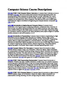
The Surface Extraction Algorithm Surfaces are identified in a sketch via a two-stage process (Figure 1). In the first stage, the rough sketch is segmented Segmentation 1) Identify junctions between polylines, segment polylines at junctions to form pseudo-edges. 2) Segment pseudo-edges at discontinuities in curvature to form edges. Grouping 3) Identify edge cycle that bounds the object. 4) Identify surfaces within the object by finding minimal closures of edges. 5) Repeat 3 & 4 for internal edges. Figure 1. The algorithm for finding surfaces 2
The notion of order in structure-mapping differs from traditional logic: it concerns depth of structure. Entities have order zero; the order of a statement is one plus the maximum order of its arguments.
into edges. In the second stage, edges are grouped together to form surfaces.
Segmentation The representation system begins with a set of polylines, lists of points representing the lines sketched by the user. It does not assume that each polyline corresponds with one edge in the sketch. Rather, it begins by looking for connections between the polylines (Step 1). If two polyline endpoints are sufficiently close to each other, the polylines will be connected by a junction. If one polyline’s endpoint is near the middle of another polyline, the second polyline will be split, and all three will be connected by a junction at the intersection point. If two polylines intersect, they will be segmented into four connected polylines. The system searches for connections iteratively at multiple scales, beginning with a small distance threshold and increasing the threshold for endpoints that fail to connect to anything. At the end of this process, any pairs of polylines that are connected by a junction containing only two polylines are joined together, since it is possible the user meant them to both be part of the same edge. The output of this process is a set of proto-edges, as well as junctions between proto-edges. Proto-edges are then segmented to form the actual edges of the sketch (Step 2). Possible segmentation points are identified by finding maximal derivates of the curvature of each proto-edge. We follow Lowe’s (1989) approach of parameterizing a proto-edge’s list of points to form x- and y-functions and convolving each function with a Gaussian and a derivative Gaussian to calculate the curvature at each point along the proto-edge. This allows the system to modify the width of the Gaussian to look for changes in curvature at different scales, depending on the length of the proto-edge. Once segmentation points are identified, they are evaluated by looking at the curvedness and relative orientation of the edge segments on either side of the point.
Grouping Here connected edges are grouped together in order to identify the surfaces of the sketch. All surfaces except the background possess an exterior, a closed cycle of edges that surrounds them. However, not every cycle of edges corresponds to a surface. Our line labeling algorithm assumes that every edge represents a boundary between surfaces. Therefore, only the minimal closures, the tightest possible cycles, correspond to surfaces in the sketch. Our system simplifies the process of surface detection and line labeling by assuming that a given sketch represents only a single object. It begins by finding the outer boundary of that object (Step 3). This is done by shooting a ray from the center of the sketch outward and identifying the last edge hit by the ray, which must be an external edge. The system then traces clockwise along the junctions between edges, always choosing the edge which is oriented the farthest in the clockwise direction, to determine the cycle of edges that make up the object’s
outer boundary. Next, the system traces both clockwise and counter-clockwise among the inner edges that connect to these external edges, in order to find both of the surfaces that meet along each edge (Step 4). This method will find all surfaces for the set of edges that are connected to the outer boundary of the sketched object. However, there may be other, internal sets of connected edges that do not connect to these edges. These internal edges might represent a hole or protuberance on the object. In order to find surfaces among the internal edges, the entire process is repeated, beginning with shooting out a ray to find an edge representing the exterior of the internal edges (Step 5). Exterior internal edges are also marked for the larger surface in which the internal set of edges is found.
Line Labelling Surface extraction returns a set of surfaces, along with the cycle of edges that bounds each surface. Line labeling is used to determine which of these edges are actually part of the surface and which edges are part of another surface that is occluding this surface. We use an extension of Malik’s (1987) line labeling algorithm that handles curved surfaces. This algorithm labels edges in a drawing as convex corners between surfaces, concave corners, occluding edges where one surface occludes another, and limb edges where a surfaces curves away from the viewer. A junction catalog specifies, for each type of junction, all possible combinations of labelings for the edges in it. Constraint satisfaction is used to solve for all edge labels. Malik’s (1987) algorithm and junction catalogue make several assumptions about the objects that are being interpreted. Unfortunately, the class of sketches we are examining, engineering design drawings, violate several of these assumptions. In the subsections that follow, we describe each of the assumptions that is violated and how we have adapted the junction catalog and labeling algorithm to deal with it. Figure 2 contains several example sketches. We will refer to specific junctions and surfaces
within this figure by letter. Figure 3 shows the additions which were made to the junction catalogue.
1) Trihedral surfaces The junction catalogue assumes that no more than three surfaces meet at any vertex. However, some of the design sketches considered contain a type of vertex made up of four surfaces, +-vertices. +-vertices are formed when two cuboids are adjacent but not quite aligned (see junction A in Figure 2). Though they are a meeting of four edges, they always appear in two-dimensional sketches as T-junctions (where two collinear edges are bisected by a third edge). We allow for these types of vertices by adding a new possible labeling for T-junctions, one in which instead of both collinear edges being occluding edges, one is an occluding edge and the other is a concave edge.
2) Piecewise smooth surfaces Malik’s algorithm assumes that surfaces curve smoothly. However, our design sketches often contain surfaces with a discontinuity in their curvature, where they change from being straight to being curved (see surface B). This type of surface has two effects. First, curved-L-junctions, where a straight edge and a curved edge meet, may appear between edges that lie along the exterior of these types of surfaces. We expanded the set of labelings for curved-L-junction to include all the labeling allowed for L-junctions (junctions between two straight edges) as well as one additional labeling in which both edges are convex (e.g., junction C). Second, there is a new type of junction, the curved-awayL-junction (junction D), in which the orientations of the straight edge and the curved edge are discontinuous at the point where they meet. This junction appears where a surface (such as B) meets another surface at the point where it changes from straight to curve. Its only possible labeling is convex for one edge and concave for the other.
3) No curved holes The existing junction catalogues contain no labellings to
Figure 2. Four of the 12 objects sketched in CogSketch
deal with circular holes. This is a problem for design sketches because objects are often designed to fit together around a cylindrical axle, so the objects will contain holes. Often these holes are drawn as a simple ellipse (junction E). Other times, they appear as curved-T junctions (junction F). Because the edge circling around a hole can vary between convex and occluding, our system simply assigns all edges around curved holes a new label, hole. In theory, an ellipse drawn by the user might indicate a sphere or a ring, as well as a hole. Our system relies on the assumption that the user is sketching only one object. Thus, any interior ellipse must be a hole. Similarly, any set of connected interior edges whose bounding edges are connected by only curved-T-junctions must be a hole. In fact, if a hole is not quite circular, it may also contain curved-L-junctions (see junction G). Thus, curved-Ljunctions that are located along the bounding edges of an interior set of edges are reclassified as interior-L-junctions, and their edges can only be labeled as hole edges. In this example, a set of connected edges that actually do connect to the exterior edges are considered interior because all connections to the exterior edges are through T-junctions (junctions H and I), indicating that this is probably a set of interior edges that have been occluded by exterior edges.
Pseudo-junction | Curved-T-junction | Interior-L-junction
Curved-L-junction | Curved-away-L-junction
| T-junction
Figure 3. Additions to the junction catalogue (+ convex, concave, ^ occluding, ^+ hole, unlabelled means unknown)
object are occluding the background surface. However, there will still sometimes be a few possible labelings for some edges. In such cases, the system simply assumes that the first labeling found is correct. Unusual junction labels, such as the new T-junction labeling, are considered last to decrease the likelihood that they will be included if a simpler globally consistent labeling is available.
Qualitative Representation 4) No accidental viewpoints Finally, traditional line labeling methods assume that drawings contain no accidental viewpoints, i.e., there are no junctions that are distorted by being viewed from just the wrong viewpoint. However, the design sketches contain two types of distortions. First, a viewpoint may place two junctions on top of each other, such that they appear to be a single junction at which four or more edges meet (junction J). Our system utilizes the simple expedient of ignoring any junction with more than three edges during labeling. Second, two connected edges that are not collinear in three-dimensional space may happen to line up in the sketch such that they appear to be collinear, causing a three-edge junction with them and a third edge to appear to be a T-junction (junction K). Our system initially looks for a normal sketch labeling and then, if this fails, looks for a labeling in which at most one T-junction in the sketch is ignored. If this fails, it increases the number of ignored Tjunctions. In principle, this approach could result in a significant loss of efficiency, but in practice we have found there is never more than one or two distorted T-junctions.
Dealing with ambiguity One weakness of the line labeling approach is that it can produce multiple consistent line labellings for a given sketch. Fortunately, the ambiguity can be decreased significantly by assuming that all the exterior edges of the
The representations generated by the system contain an entity for each edge and each surface found in the sketch. In addition, they contain three types of qualitative spatial relations between these entities: corners along a surface, corners along an edge, and parallel surface relations. Corners are relatively local, and thus are represented as only first- or second-order relations. Parallel surface relations are more global, relating large parts of a sketch.
Corners along a surface
Every surface except the background has a cycle of edges that bound it. The edge labels tell the system which of these edges actually lie along the surface, rather than occluding the surface. For each pair of adjacent edges along a surface, the system asserts a relation describing the corner between them. Typically, corners are classified as convex or concave, although several additional classifications are used for corners that fall along unusual junctions (e.g., corners where a flat surface and a curved surface meet). Second-order relations are asserted to describing adjacent pairs of corners along a surface. See Figure 4 for a simple example.
Corners along an edge
Each edge labeled either convex or concave is a corner between two surfaces. Basic, first-order relations are asserted to describe these corners.
To simplify the process of representing holes, a single entity is constructed for a given hole, regardless of the number of surfaces actually found within the hole. Then, each of the edges along the hole is represented as a boundary between the surrounding surface and the hole. Second-order relations are included to represent pairs of adjacent edges that lie around a hole. However, none of the edges lying within the hole are represented. Thus, anything located along the inside of a hole or visible through the hole is ignored in the present representation scheme.
Parallel surface relations
The corner relations described thus far are fairly local. An object may contain a large number of similar-looking corners. A representation consisting only of a large number of similar, low-level relations causes problems for SME, because SME does not perform an exhaustive search for an optimal mapping. Thus larger-scale, higher-order relations are required to anchor the match. We rely on a heuristic about parallel edges in drawings to infer higher-order structure. As Varley, Martin, and Suzuki (2005) observe, parallel lines in a drawing usually correspond to parallel edges in the three-dimensional object being drawn. Therefore, if in the sketch one planar surface has a corner A and another planar surface has a corner B such that the first edge of corner A is parallel to the first edge of corner B and the second edge of corner A is parallel to the second edge of corner B, then the two surfaces are almost certainly parallel in three dimensions. The system asserts three types of parallel surface relations for surfaces that possess corners with pairs of parallel edges. The first is for cases when one of the pairs of edges is actually collinear. In this case, the evidence for the surfaces being parallel is greatest because collinear lines in a drawing nearly always correspond to collinear edges in three dimensions (Varley et al., 2005). The system asserts a higher-order relation stating that the colinearity of the two edges supports the two surfaces being parallel. The second type of relation is for cases where the parallel surfaces are each connected to the same third surface by parallel edges. A higher-order relation is asserted stating that the fact that the two corners between the parallel surfaces and the third surface are parallel supports the belief that the two surfaces are parallel. The third type is for all other cases where two surfaces have corners with pairs of parallel edges. This is the weakest evidence for parallel surfaces, so the system simply asserts a first-order parallel surface relation. All of the parallel surface relations described thus far are symmetric relations. A symmetric relation is one in which the order of the arguments can be reversed. For example, the relation (parallelSurfaces A B) is identical to (parallelSurfaces B A). This representation makes no commitment about the relative position or orientation of the edges and surfaces being related. People clearly use some orientation-specific information when comparing images, so we include orientation-specific higher-order relations to aid SME in finding the correct
mapping. The system asserts an orientation-specific version of the parallel surface relation for collinear edges. Thus, while a mapping can be found between any pair of collinear edge relations, there will be a stronger mapping in cases where the relative position and orientation of the edges and surfaces is maintained.
Comparing Shapes Given two sketches in CogSketch, our system generates qualitative representations of them as described above and uses SME to find a mapping between them. Given the nature of sketches, we add two additional constraints to the matching process. A mapping is coherent if edges that are connected in the base sketch correspond to edges that are connected in the target sketch. In cases where two edge mh’s (match hypotheses between an edge in the base and an edge in the target) in a mapping are inconsistent, e.g., the two base edges are connected while the two target edges are unambiguously disconnected, both edge mh’s are removed from the mapping, along with any mh’s between relations that take those edges as arguments. In cases where an edge mh is inconsistent with a large number of other edge mh’s, the entire SME match will be rerun with the constraint that the faulty edge mh must be excluded from all mappings. This may allow SME to find a superior mapping that it failed to find on the first run because of being distracted by incoherent edge matches. A mapping is complete if every edge mh that can be included in the mapping without violating mapping coherence is included. This completeness criterion is very useful when SME is being used to recognize when two sketches are of the same object. Incomplete edge mh’s are identified by finding where both the base edge and the target edge connect to additional edges that have been left out of the mapping. Note that if, say, only the base edge connects to additional edges, there is no problem; it may be that the corresponding edges are occluded in the target. Completeness is implemented by forbidding incomplete edge mhs to appear in mappings, along with any mhs between relations that take those edges as arguments.
Evaluation We evaluated our system using a set of 12 sketched objects taken from an exercise in an introductory engineering adjacent corners
convex corner
Edge-A
Edge-B
Second-Order Relation
concave corner
Edge-C
Figure 4. Typical corner relations
First-Order Relation Entity
design textbook (Lueptow, 2007). In the exercise, sets of four objects were shown in each of three sketching perspectives (isometric, oblique, and orthographic), and students were asked to sketch the objects in the other two perspectives. These sketches were chosen because they were a beginning exercise, and hence not overly complicated, while still being representative of the kinds of 3D sketches engineers would be required to make. We tested the system’s ability to recognize oblique and isometric perspective sketches of the same object. The orientations of these two perspectives are about 45˚ different, resulting in a number of differences in the sketches. See Figure 2 for examples of four objects; the top row are sketched at an oblique perspective, and the bottom row are sketched at an isometric perspective. A design student was asked to draw all 12 objects in both an oblique and and an isometric perspective. Then, one of the experimenters sketched each of the objects in CogSketch, using the student’s sketches as a guide but making corrections where the student had made mistakes, such as forgetting to draw a hole in a surface. Our system computed qualitative representations for all 24 sketches. Because only one of the objects contained internal edges that were not part of a hole, those edges were left out of the representation. Each sketch was then compared to the other 23 sketches using SME. The measures of success were (a) whether the line labeling algorithm provided correct results on each sketch, and (b) whether a given sketch’s closest match was the other sketch of the same object, based on SME’s mapping score.
Results
The output of the line labeling algorithm yielded correct results on all edges for 22 of the 24 sketches. The other two sketches showed minor mistakes; typically the correct labeling had also been found, but it was not the first labeling returned by the algorithm. The recognition evaluation showed an overall success rate of 20/24, or 83%. That is, for 20 of the 24 sketches, the best mapping found by SME was with the other sketch of the same object. Because there were 22 distractor sketches, chance performance would be 1/23, or 4%. The four mistakes occurred due to the failure of the system to recognize either of the perspectives of two of the objects. The rightmost object in Figure 2 is one of these. These objects contained partially curved edges that proved difficult to segment consistently. Also, the other problem object was rotated enough to make a single surface in one perspective appear to be two surfaces in the other.
Related Work Most work on sketch recognition focuses on recognizing objects drawn at the same orientation. Nonetheless, recognition systems with quantitative representation systems often require 20-50+ training examples per category (Liwicki & Knipping, 2005; Sharon & van de
Panne, 2006), or can only be trained and evaluated on sketches by a single user (Sezgin & Davis, 2007). Previous work on constructing three-dimensional representations of sketches has tended to focused on recovering frontal geometry (Varley et al., 2005; Kaplan & Cohen, 2006), i.e., the distance to each point along the visible surfaces. Because these distances change as surfaces rotate in space, it is unclear whether this type of representation would be useful in comparing two sketches of an object at different orientations.
Discussion and Future Work In the evaluation, our system demonstrated that it was capable of constructing qualitative spatial representations sufficiently robust to recognize two sketches of an object drawn at different orientations, despite a large number of distracters. Of the 12 objects being represented, only 2 caused problems for the system. We believe that these initial results are promising, and that they show it is possible, using qualitative representations, to accurately compare different-looking sketches of the same object, at least within the domain of engineering design. However, the system possesses a major limitation. While it allows for a few junction distortions due to the viewpoint, it assumes the user has sketched the object nearly perfectly, allowing a globally consistent line labeling to be found. This is fine for experts, but for naïve users, a more flexible line labeling strategy will be needed. The probabilistic line labeling algorithm developed by Varley et al. (2004) is one promising option. Being able to construct robust qualitative 3D representations from 2D sketches and identify them via comparison will facilitate using sketch understanding in a variety of applications. These include education in engineering, geoscience, and other highly spatial areas, plus support tools for creative conceptual design. We hope to explore these in future work.
Acknowledgements This work was supported by NSF SLC Grant SBE0541957, the Spatial Intelligence and Learning Center (SILC).
References Falkenhainer, B., Forbus, K., and Gentner, D. 1986. The Structure-Mapping Engine. In Proceedings of AAAI ’86. Forbus, K., Usher, J., Lovett, A., Lockwood, K., and Wetzel, J. 2008. CogSketch: Open-Domain Sketch Understanding for Cognitive Science Research and For Education. In Proceedings of Eurographics Sketch-Based Interfaces and Modeling.
Forbus, K., Ferguson R., and Usher, J. 2001. Towards a computational model of sketching. In Proceedings of Intelligent User Interfaces. Gentner, D. 1983. Structure-Mapping: A Theoretical Framework for Analogy. Cognitive Science 7(2): 155-170. Kaplan, M., and Cohen, E. 2006. Producing models from drawings of curved surfaces. Workshop on SketchBased Interfaces and Modeling. Liwicki, M., and Knipping, L. 2005. Recognizing and Simulating Sketched Logic Circuits. In Proceedings of the 9th International Conference on Knowledge-Based Intelligent Information & Engineering Systems, 588 – 594. Lovett, A., Dehghani, M., and Forbus, K. 2007a. Incremental Learning of Perceptual Categories for Opendomain Sketch Recognition. In Proceedings IJCAI ’07. Lovett, A., Forbus, K., and Usher, J. 2007b. Analogy with Qualitative Spatial Representations Can Simulate Solving Raven’s Progressive Matrices. In Proceedings of the 29th Annual Conference of the Cognitive Society. Lueptow, R. M. 2007. Graphic Concepts for Computer Aided Design. Upper Saddle River, NJ: Prentice Hall. Malik, J. 1987. Interpreting Line Drawings of Curved Objects. International Journal of Computer Vision 1: 73103. Sharon, D., and van de Panne M. 2006. Constellation Models for Sketch Recognition. In 3rd Eurographics Workshop on Sketch-Based Interfaces and Modeling. Sezgin, T. M., & Davis, R. 2007. Sketch interpretation using multiscale models of temporal patterns. IEEE Computer Graphics and Applications 27(1): 28-37. Tomai, E., Lovett, A., Forbus, K., and Usher, J. 2005. A Structure Mapping Model for Solving Geometric Analogy Problems. In Proceedings of the 27 th Annual Conference of the Cognitive Science Society. Varley, P. A. C., Martin, R. R., and Suzuki, H. 2005. Frontal Geometry from Sketch of Engineering Objects: Is Line Labelling Necessary? Computer-Aided Design 37: 1285-1307. Varley, P. A. C., Martin, R. R., and Suzuki, H. 2004. Making the Most of Using Depth Reasoning to Label Line Drawings of Engineering Objects. In Proceedings of the 9 th ACM Symposium on Solid Modeling and Applications.