Interservice/Industry Training, Simulation, and Education Conference (I/ITSEC) 2006
Building Distributed Simulations Utilizing the EAAGLES Framework Douglas D. Hodson Capabilities Integration Directorate Wright-Patterson AFB, OH
[email protected]
David P. Gehl L-3 Communications Link Simulation & Training Dayton, OH
[email protected]
Rusty O. Baldwin Air Force Institute of Technology WPAFB, OH
[email protected]
ABSTRACT The Extensible Architecture for the Analysis and Generation of Linked Simulations (EAAGLES) software is a framework for the design of robust, scalable, virtual, constructive, stand-alone, and distributed simulation applications. Its design integrates concepts from both virtual and constructive simulations to achieve an optimal blend of both. The Simulation and Analysis Facility (SIMAF) located at WPAFB, Ohio, participates in a number of distributed events each year. The vast majority of the distributed simulation software used in the facility has been “home grown” utilizing the EAAGLES framework which provides native interfaces to the Distributed Interactive Simulation (DIS) protocol and High Level Architecture (HLA). Applications built utilizing the framework include cockpits (F-16), ground control stations (Predator MQ-9), threat Integrated Air Defense Systems (IADS) and a futuristic battle manager. Interfaces to other systems, such as Simulink-based models, have also been developed. This paper describes the distributed software architecture and explains how to take advantage of low-cost dual processor PCs to support real-time simulation systems. ABOUT THE AUTHORS Douglas D. Hodson is an Electrical Engineer at the Simulation and Analysis Facility, Wright Patterson Air Force Base AFB, OH. He is the technical lead of the Extensible Architecture for the Analysis and Generation of Linked Simulations (EAAGLES) software framework. This framework is currently being used to support the development of both virtual and constructive and stand-alone and distributed simulation applications. He received a B.S. in Physics from Wright State University in 1985, and both an M.S. in Electro-Optics in 1987 and an M.B.A. in 1999 from the University of Dayton. He is also a graduate student and Adjunct Instructor at the Air Force Institute of Technology working towards his Ph.D. in Computer Engineering. David P. Gehl is employed by L-3 Communications, Link Simulation & Training Division. He has over 30 years of experience in man-in-the-loop simulation and training for human factors engineering research including extensive knowledge in pilot/operator-vehicle interfaces, aircraft system models (aerodynamics, radars, weapon delivery, navigation, visual systems, etc.), and real-time system development. Currently he serves as the primary architect for the Extensible Architecture for the Analysis and Generation of Linked Simulations (EAAGLES) simulation framework. He holds a B.S. in Computer Science in 1979 and a M.S. in Systems Engineering in 1986 from Wright State University. Rusty O. Baldwin is an Associate Professor of Computer Engineering in the Department of Electrical and Computer Engineering, Air Force Institute of Technology, Wright-Patterson AFB, OH. He received a B.S. in Electrical Engineering (cum laude) from New Mexico State University in 1987, an M.S. in Computer Engineering from the Air Force Institute of Technology in 1992, and a Ph.D. in Electrical Engineering from Virginia Polytechnic Institute and State University in 1999. He served 23 years in the United States Air Force. He is a registered Professional Engineer in Ohio and a member of Eta Kappa Nu, and a Senior Member of IEEE. His research interests include computer communication networks, embedded and wireless networking, information assurance, and reconfigurable computing systems.
2006 Paper No. 2628 Page 1 of 10
PREPRINT
Interservice/Industry Training, Simulation, and Education Conference (I/ITSEC) 2006
Building Distributed Simulations Utilizing the EAAGLES Framework Douglas D. Hodson Capabilities Integration Directorate Wright-Patterson AFB, OH
[email protected]
David P. Gehl L-3 Communications Link Simulation & Training Dayton, OH
[email protected]
INTRODUCTION The Simulation and Analysis Facility (SIMAF) located at Wright Patterson AFB (WPAFB), Ohio participates in a number of distributed simulation activities each year that include live, virtual (human-inthe-loop) and constructive players/entities. The majority of the distributed simulation applications have been developed using the Extensible Architecture for the Analysis and Generation of Linked Simulations (EAAGLES) software framework.
Rusty O. Baldwin Air Force Institute of Technology WPAFB, OH
[email protected]
fense Systems (IADS) and a futuristic battle manager. FRAMEWORKS, TOOLKITS & APPLICATIONS A framework is a set of cooperating classes that make up a reusable design for a specific class of software (Deutsch, 1989; Johnson, 1988). A framework is customized to a particular application by creating application-specific subclasses of abstract classes from the framework (Gamma, 1995). A toolkit is a set of related and reusable classes that provide useful, general-purpose functionality. They are the objectoriented equivalent of subroutine libraries (Gamma, 1995).
EAAGLES is a simulation design pattern that provides a structure for constructing simulation applications. The framework aids the design of robust, scalable, virtual, constructive, stand-alone, and distributed simulation applications. It leverages modern object-oriented software design principles while incorporating fundamental real-time system design tech- EAAGLES itself is not an application. Applications are stand-alone executable software programs like Miniques to meet human interaction requirements. crosoft Word. They typically satisfy a particular By providing abstract representations of system com- need. ponents (that the object-oriented design philosophy EAAGLES is an object-oriented modeling and simpromotes), multiple levels of fidelity can be easily ulation framework coded in C++. It is partitioned intermixed and selected for optimal runtime perforinto packages that serve as functional toolkits for the mance. Abstract representations of systems allow a developer. One example would be the EAAGLES developer to tune the application to run efficiently so graphics toolkit, which facilitates the development of that human-in-the-loop interaction latency deadlines operator/vehicle interfaces and displays. can be met. On the flip side, constructive-only simulation applications that do not need to meet time- The framework enables the creation of a diverse set of critical deadlines can use models with even higher simulation applications. Derived simulation applicalevels of fidelity. tions using the framework can be run stand-alone or distributed. Distributed applications can interoperThe framework embraces the Model-View-Controller ate with other systems and simulations through DIS (MVC) software design pattern by partitioning funcand/or HLA interfaces. The application might intional components into packages. This concept is clude software agents that represent human partictaken a step further by providing an abstract network ipation (constructive), or it might need to interact interface so custom protocols can be implemented with a real human participant (virtual). without affecting system models. Examples include the Distributed Interactive Simulation (DIS) protocol and the High Level Architecture (HLA) interfaces. HUMAN INTERACTION & VIRTUAL SIMULATION Specific applications using the framework to support simulation activities include representative F-16 cockpits, an Unmanned Aerial Vehicle (UAV) ground Simulations that interact with human participants control station (Predator MQ-9), Integrated Air De- must respond within a prescribed deadline (latency 2006 Paper No. 2628 Page 2 of 10
PREPRINT
Interservice/Industry Training, Simulation, and Education Conference (I/ITSEC) 2006
or response time). A simulation that does not respond like the system it is intended to represent will frustrate the operator and may skew the simulation results. Software systems faced with this demanding requirement fall into the category of real-time systems.
oriented languages tend to be viewed with skepticism as overall system performance often outweighs flexibility. But for the modeling and simulation domain, the advantages afforded by an object-oriented language outweighs this slight performance penalty.
Real-time systems are designed and organized so that time-critical (often periodic) tasks can meet their deadlines. Two standard approaches to scheduling tasks include priority-based and foreground/background systems. Priority-based designs assign a priority to each task in the system. The task with the highest priority that is ready to run is executed first. The scheduling of the task resides with the operating system.
• C++ is portable and compilers exist on virtually every platform. This allows developers to build EAAGLES-based applications on any of the major popular operating systems (Windows, Linux, IRIX, Solaris, etc).
In a foreground/background system the application controls the scheduling of tasks. Foreground tasks are executed with the help of a jump-list, or a managed list of pointers to functions (tasks). Tasks are executed one after another as defined by the list order. Aperiodic events and background tasks receive processing time after all the “highest priority” tasks in the list have finished. EAAGLES is a foreground/background system, but instead of managing a jump-list (or a list of functions to process), scheduling is interwoven into the object hierarchy. It is specifically designed to take advantage of low-cost dual processor PCs which allow the creation of a time-critical foreground thread. Because multiple processors are available, reliable execution of a time-critical thread is assured with general purpose operating systems such as Windows and Linux. It should be emphasized that EAAGLES is a cycle or frame-based system, not a discrete-event simulator. This approach satisfies the requirements for which it is designed; namely, support for models of varying levels of fidelity including higher level “physicsbased” models, digital signal processing models and the ability to meet real-time performance requirements. Model state can be captured with state machines and state transitions can use the message passing mechanisms provided by the framework.
• C++ is flexible. • It is desirable to define memory management so it does not interfere with the overall performance of the application. Therefore, the use of the New/Delete operators is preferable to garbage collection. It is beyond the scope of this paper to cover each and every class defined in the framework, but a few key classes deserve attention in order to gain insight into the structure of the framework. Object : The Object class is the C++ system object for the EAAGLES framework. Unlike other object oriented languages (for example Java or Ruby), the C++ language does not provide a system object. C++ also does not provide native garbage collection. While lacking these two features could be viewed as a negative when comparing the native features of various languages, it is a positive when the application domain consists of applications that need to meet real-time requirements.
C++ provides the flexibility to define how these mechanisms work for different application domains. For example, if the developer is writing an application in which “control” over potentially time-consuming memory management operations is of little concern, the framework provides smart pointers to automatically manage the creation and deletion of objects. If, on the other hand, the application has time constraints to meet (i.e. a real-time system), the “uncontrolled” creation and destruction of objects will lead to performance problems. One of Objects capabilities AN OBJECT-ORIENTED REAL-TIME is to provide a simple reference counting system for FRAMEWORK the memory management of all framework objects. Object provides access to this system so that a developer can manually control and tune performanceEAAGLES is an object-oriented C++ simulation oriented applications, if they arise; for example, the framework. C++ was chosen since: processing, in real-time, of modeled radio frequency • Most real-time systems are developed in C for (RF) emission packets or infrared radiation (IR) geperformance reasons (Laplante, 2004). Object- ometry information.
2006 Paper No. 2628 Page 3 of 10
PREPRINT
Interservice/Industry Training, Simulation, and Education Conference (I/ITSEC) 2006
The other subtle but important aspect to providing a system object appears in the form of typechecking. The presence of a system object, and the derivation of all classes from it, enables the dynamic casting of objects. It also avoids the pitfalls associated with untyped functions and classes. The EAAGLES coding standard explicitly prohibits the use of void pointers for this very reason. Component : In object-oriented programming, a container class is a class of objects that contain other objects. The EAAGLES component class is that and much more. Component is a container for other components. Component also defines a basic messaging system that is used throughout the framework. From the outset, the EAAGLES framework is designed to facilitate the creation of simulation applications that execute in real-time and/or interact with a human participant. Applications with time constraints and latency/response deadlines typically separate time-critical tasks and non-time-critical tasks; for example, the execution of an aerodynamic model at a specific frequency as opposed to writing data to a hard disk, or printing a document.
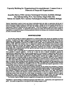
Figure 1: Component Tree The EAAGLES coding standard spells out basic rules to follow when writing code in updateTC (example: no blocking I/O calls). These rules parallel many of the rules used when designing real-time systems.
SIMULATION ARCHITECTURE A developer using the EAAGLES framework as a basis for a simulation typically builds an application by either using existing classes (or models) or extends them to add new functionality. Then the developer writes the mainline (main()) for the application.
This separation is facilitated by two methods in the The mainline usually has the following structure: component class. When designing a model in the • Read an input file that describes the framework, code that needs to execute in a timeclass/object hierarchy and associated atcritical manner (usually mathematical calculations) tributes. EAAGLES provides a parser (written is placed in an overridden virtual updateTC (update with Flex and Bison) that can read a simple time-critical) method. Code that can be run in a context-free scheme-like input language. non-time-critical manner is placed in the overridden • Setup the threads as desired. For applicavirtual updateData method. tions without real-time requirements (e.g., a constructive-only application that processes a This organization of code has a number of advanseries of batch runs) a single thread is all that tages: is needed. For a virtual simulation with time• Since time-critical code is clearly separated critical code, a time critical (or high priority) from background code, applications can be dethread should be created. signed to meet performance requirements. • Start the simulation by calling updateTC and updateData as required. If it is a virtual sim• All the code (time-critical and background) asulation or a simulation where real-time persociated with a model is logically within the formance is important, the time-critical thread same class. will call the updateTC method of the root node. Stepping back, one can view an instance of a sim- Full control of the mainline is in the hands of the deulation application as nothing more than a tree of veloper for maximum flexibility. EAAGLES does not Components as in Figure 1. A call to the top (or even provide a main() function! Furthermore, appliroot) of the tree’s updateTC method, will automat- cation mainlines tend to be short and sweet. Most of ically execute every subcomponent’s updateTC. In the work is in the design and extension of new classes. other words, every component will execute the code of its children. This process continues until the en- Simulation applications are typically organized like tire tree has been processed. The same process takes the structure as shown in Figure 2. Thinking in terms place for the background code. of a tree of components, the class Station resides at 2006 Paper No. 2628 Page 4 of 10
PREPRINT
Interservice/Industry Training, Simulation, and Education Conference (I/ITSEC) 2006
Figure 2: Structure of Simulations the top, or the root node. Every other component is a subcomponent of Station. Station connects models to views (or graphical displays) and controls. As mentioned earlier, the EAAGLES framework embraces the Model-ViewController (MVC) software design pattern. Station also owns an instance of the Simulation object which manages a list of players (entities), keeps track of simulation time, which includes the cycle, frame and phase that is currently being processed. Being a frame-based system (not a discrete-event simulator), delta time is passed as an argument to updateTC so proper calculations involving time can be performed. Having models rely on delta time for calculation means the frequency of the entire system can change without having to change each and every model (so long as Nyquist rates are met). Additional time related information is recorded in terms of cycles (16 frames or sometimes called a major frame) and phases. Phases sequence the flow of data throughout a model. Four phases are currently defined:
• Transmit – R/F emissions, which may contain datalink messages, are sent during this phase. The parameters for the R/F range equation, which include transmitter power, antenna pattern, gains and losses, are computed. • Receive – Incoming emissions are processed and filtered, and the detection reports or datalink messages are queued for processing. • Process – Used to process datalink messages, sensor detection reports and tracks, and to update state machines, on-board computers, shoot lists, guidance computers, autopilots or any other player or system decision logic. A Player is a subclass of component that adds dynamics and other unique behaviors. Some components that can be “attached” include signatures, antennas, sensors and stores. Derived air and ground players are included within the framework.
An abstract interoperability network interface is defined so specific protocols can be incorporated, such as DIS, for interacting with other distributed simu• Dynamics – update player or system dynamics lation applications. This network interface automatincluding aerodynamic, propulsion, and sensor ically creates new players in the player list. As far positions (e.g., antennas, IR seekers). as the simulation is concerned, these players are like
2006 Paper No. 2628 Page 5 of 10
PREPRINT
Interservice/Industry Training, Simulation, and Education Conference (I/ITSEC) 2006
any other.
GRAPHICS ARCHITECTURE The framework defines several graphic toolkits for the development of operator/vehicle interface displays. The graphic toolkits are based on OpenGL for all primitive drawing, thus making the framework compatible with virtually any platform.
EAAGLES graphic classes ease the development of operator/vehicle displays and leverage open source GUI toolkits, but they are not intended to replace visual scenegraph displays (such as heads up displays). The overarching philosophy of EAAGLES is to avoid reinventing the graphics “wheel”.
Higher level toolkits that use this structure include the instrument library which includes dials, buttons, gauges, meters, pointers, and countless other fully functional instruments, along with simple maps. The The foundation for graphics drawing is contained in moving map library is another such library. the basicGL package. It contains classes for drawing All of the graphical toolkits are independent of the graphic objects such as bitmaps, input/output fields, simulation modeling environment. Models don’t have fonts, polygons, readouts, textures, and others. any knowledge of graphics and graphics have no The graphics architecture has key fundamental re- knowledge of models. The code that connects the lationships between the Graphic, Page and Display two resides within the application and is typically associated with the Station class. classes (see Figure 3). Object
Component
Graphic
Page
Display
GlutDisplay
FoxDisplay
Through an ownship pointer in the Station class, the controls and displays of any player can be switched at anytime. Switching from player to player is useful for observing simulation interactions from different perspectives. All of the graphics classes are derived from Graphic which is derived from Component. Being a component, all time-critical code can be written into the updateTC method and background processing can be written into the updateData method. Sometimes, in real-time system development, it is desirable to set graphic drawing to an even lower priority than other background processing. Therefore, another method within the Graphic class is defined that serves as a placeholder to do actual OpenGL graphics drawing. Object
Figure 3: Graphics Class Hierarchy The Graphic class encapsulates attributes associated with a graphic such as color, line width, flash rate (for a graphic that flashes), coordinate transformations, vertices and texture coordinates, select names and scissor box information. Since Graphic is a component, it can contain other graphics. Page is a “page” of graphics that can facilitate the creation of MultiFunction Displays (MFD) where specific page transition events need to be defined. The Display class defines all the resources available for drawing such as fonts, the color table and both the physical and logical dimensions of the display viewport. Finally, open source GUI toolkits (such as Glut, Fox and FLTK) are included in EAAGLES through their respective display classes. 2006 Paper No. 2628 Page 6 of 10
IODevice
Joystick
USB
Figure 4: Device Class Hierarchy A sample application included in an EAAGLES distribution illustrates basic graphics by drawing a “worm” that moves around the screen and “bounces” off the walls. Code for this example is organized as follows. All mathematical calculations for the position, speed and direction of the worm are performed in updateTC. All the work to setup what to draw is done in updateData. The actual drawing of the PREPRINT
Interservice/Industry Training, Simulation, and Education Conference (I/ITSEC) 2006
Figure 5: Generic Heads Down Display graphic is performed by Graphic’s draw function.
shown in Figure 4. This deviceIO package has interface code for several platforms that support joysticks, Organizing code this way enables the application de- USB devices, BG System serial boxes and Keithley veloper to determine how to execute the code and to PCI digital acquisition cards. define threads to meet requirements. For this example, a thread is set up to execute time-critical mathematical calculations associated with the worm in “real-time”, and in a non-time-critical manner the opOnce the device is initialized, a call to the virtual reerating system (or Glut in this case) draws the worm ceive method, defined in the IODevice class, obtains during idle times. the latest values from the device. Information about button transitions can also be determined as well as the definition of deadbands for analog inputs. DEVICE I/O ARCHITECTURE The EAAGLES framework abstracts I/O devices so each hardware interface appears to the application The Station class defines how axes and buttons are developer as nothing more than a device with a num- “connected” to the models and views of the simulaber of analog (axis) and digital (button) values as tion application. 2006 Paper No. 2628 Page 7 of 10
PREPRINT
Interservice/Industry Training, Simulation, and Education Conference (I/ITSEC) 2006
Figure 6: MQ-9 Ground Control Station FIGHTER COCKPIT
cockpit is really a simulation entity that is being flown by a human operator. Since the controls and displays are logically separate from the player model, switchOne of the first EAAGLES-based applications deing and controlling different players during a run can veloped at the SIMAF facility was a generic fighter be as simple as moving the ownship pointer. cockpit with a generic heads down display. The heads-down display was developed using the graph- This application is used in almost every distributed ics toolkit as a foundation (see Figure 5). Window simulation activity SIMAF participates in or sponmanagement is controlled by Glut which is a Display sors. It is also used by a number of facilities throughthat contains other Graphic objects and Displays as out the different services. highlighted in the figure. The Displays have multiple pages of graphics. This work effectively jump started MQ-9 GROUND CONTROL STATION the creation of the instrument library which continues to mature and expand in scope as well as across application domains. Compared to the fighter cockpit, the Predator MQ-9 Ground Control Station (GCS) in Figure 6 appears To the casual observer, the fighter application might as a completely different simulation application alappear to be nothing more than a pretty cockpit, but though it is also using the EAAGLES framework. It it is actually much more. The application driving the is a good example of leveraging different frameworks cockpit is an entire simulation ready to be connected and toolkits to their fullest potential to build an apinto a distributed virtual simulation via DIS or HLA. plication. The cockpit itself is set up through the Station class where the heads-down display and controls are asso- For example, the real GCS controls a Predator with ciated with one of the players in the simulation player two sets of control sticks. One set controls or flies the list via ownship pointer. In other words, the fighter Predator directly, and the other controls the sensor 2006 Paper No. 2628 Page 8 of 10
PREPRINT
Interservice/Industry Training, Simulation, and Education Conference (I/ITSEC) 2006
Figure 7: Group Command Post ball attached to the UAV. Four displays are presented to the operators: a tracker display in which the operator defines and uploads routes for the Predator to follow; a visual of what the sensor ball is looking at; and two lower displays with multiple pages of textual status information. The ground control station is simulated with a few EAAGLES-based applications and the Fox GUI toolkit which is a windows based application with menus and dialog boxes used to build the tracker application. EAAGLES-based OpenGL graphics draws the tracker map for planning routes.
EAAGLES DeviceIO library. SubrScene is freely distributed among the government community. The application is designed to provide a central interface to a clustered real-time rendering system for virtual emersion. It supports standard API’s such as the Common Image Generator Interface (CIGI) from Boeing and COTS modeling formats for databases and simulation reuse. Support for modular capabilities, such as plug-ins for both interfaces at the central server and rendering stages, increases unique capabilities.
SubrScene, an Image Generation System (IGS), generates a visual scene of what the sensor ball is view- This application is routinely used by SIMAF in the ing and is controlled by another EAAGLES-based Air Forces Virtual Flag event conducted several times application. All control sticks and inputs use the each year. 2006 Paper No. 2628 Page 9 of 10
PREPRINT
Interservice/Industry Training, Simulation, and Education Conference (I/ITSEC) 2006
GROUP COMMAND POST
EAAGLES is government-owned and not proprietary. It is managed by the SIMAF facility located at The Group Command Post (GCP) is a key com- WPAFB, OH. ponent of an overall Integrated Air Defense System In order to encourage the use of the EAAGLES (IADS). The GCP receives tracks formed from early framework throughout the modeling and simulation warning radar posts and filter centers under its con- community, a nearly fully featured version of the trol and develops a sector air picture. It determines framework has been released into the public domain which tracks are hostile and assigns the appropriate under the name OpenEaagles. It can be freely downweapons system to counter the threat directly, by as- loaded from www.OpenEaagles.org. signing the threat to a surface to air missile, antiaircraft artillery, airborne interceptor or indirectly assigning the threat to a weapons post responsible for ACKNOWLEDGEMENTS assigning the appropriate weapon system (see Figure 7). The success of the EAAGLES framework is the diThis application, along with two other EAAGLES- rect result of the cooperative efforts of several conbased applications (Early Warning Radar Post and tractors including L-3 Communications, SAIC, GenSAM site), forms the core of the IADS infrastructure. eral Dynamics and Booz Allen Hamilton. Each conThis infrastructure is used in a number of distributed tractor, or more importantly, each person working on simulation events including Airborne Electronic At- “EAAGLES-related” tasks has improved EAAGLES tack (AEA) which examines the impacts of various either through direct framework support or using electronic warfare techniques upon both an enemy’s EAAGLES to build new and interesting simulation integrated air defense system and blue force capabil- applications. Their contribution is gratefully acities. knowledged. FINAL THOUGHTS
REFERENCES
The EAAGLES framework is designed for the simu- Deutsch, L. Peter, Design reuse and frameworks in the Smalltalk-80 system. Software Reusability, lation application developer; it is not an application Volumne II: Applications and Experience, pages itself. It can be thought of as a simulation design that 57-71. Addison-Wesley. encourages a certain structure (shown in Figure 2) for a simulation. Gamma, Erich, et al (1995). Design Patterns, Elements of Reusable Object-Oriented Software, The framework embraces the object-oriented Addison-Wesley. paradigm and therefore system abstractions while interweaving design concepts from real-time systems Johnson, Ralph, et al. (1988). Designing reusable to achieve what we feel is an ideal structure in which classes. Journal of Object-Oriented Programming, to build simulation applications. By partitioning the 1(2):22-35. time-critical code as the framework expects, immediate use of models containing the code in virtual Laplante, Phillip A. (2004). Real-Time Systems Design and Analysis, Wiley-Interscience. simulation becomes possible. The framework is routinely compiled with Microsoft Lui, Jane W.S. (2000). Real-Time Systems, PrenticeHall. Visual Studio for the Windows environment and GCC for Linux. Applications perform best when exRoberts, Don, et al. Evolving Frameworks, A Patecuted on dual-core or dual-CPU systems because of tern Language for Developing Object-Oriented the priority based threading in these systems. WinFrameworks, University of Illinois, http://stdows and Linux are both designed for general purwww.cs.uiuc.edu/users/droberts/evolve.html. pose processing, not real-time processing, thus, one cpu can be dedicated to the operating system ker- Singhal, Sandeep, et al. (1999). Networked Virtual Environments, Design and Implementation, nel which reduces the possibility of interfering with a Addison-Wesley. time-critical task.
2006 Paper No. 2628 Page 10 of 10
PREPRINT