Author manuscript, published in "CVE 2000 (2000)"
Building Objects and Interactors for Collaborative Interactions with GASP Thierry Duval and David Margery IRISA — SIAMES project Campus de Beaulieu F-35042 Rennes cedex FRANCE
[email protected],
[email protected]
inria-00534145, version 1 - 8 Nov 2010
ABSTRACT Gasp (General Animation and Simulation Platform) was at first designed to distribute the animation and simulation of multi-agent virtual environments. In the Gasp framework, a virtual world is composed of any number of simulation objects. These simulation objects can be autonomous agents, interactors or user representations. We define interactors as simulation objects which provide information on user input readable by any simulation object. Because simulation objects can read information from any number of other simulation objects, it is then quite easy to design objects on which any number of users (or other simulation objects) can collaborate. As the Gasp run-time kernel can distribute the calculations associated with those simulation objects on different workstations, collaborative virtual environments can easily be built. In this paper, we explain how, in our framework, interactors and interactive objects are distributed for collaborative interactions and how it is possible to build an interactive object from an existing object without changing the code of that object.
Keywords Human-Computer Interfaces, Synchronous Cooperation, Distributed Virtual Reality, Distributed Interactions
1.
framework to the designer to hide some of the complexity. These toolkits are varied in the sense that they do not all address the same problems. For instance, Aviary[10] enables the sharing of a virtual world between different applications or users whereas VR Juggler[5] focuses on providing abstract layers for all the components one immersive distributed virtual reality application. With Gasp, our focus has been to enable the construction of worlds populated by interacting autonomous agents in a way that would enable an easy distribution of the workload associated with the calculations of the agents. To achieve such a goal, we have provided [9] a framework (base classes and programming rules in our case) to the designer of agents of the virtual world and a run-time environment which deals with scheduling the calculations, networking and coherence issues, interactors and display. This framework has proven more general than a framework tailored solely for the conception of agents as it can be successfully used to abstract input devices as well as output devices. Indeed, within Gasp, the visualization as well as input devices are agents of the same nature as the autonomous agents that populate the world, providing us with a quite powerful paradigm. We therefore use the term simulation object instead of agent.
INTRODUCTION
Building, calculating and displaying distributed interactive virtual environments is a complex task because of the wide variety of skills and techniques involved. These skills and techniques include those of rendering and animating the virtual environment, dealing with the I/O subsystem for interaction as well as artificial intelligence for autonomous agents and networking for the distribution and the coherence of the virtual world. This complexity has led to the development of a wide variety of toolkits or frameworks for virtual reality which either provide an abstraction layer or a dedicated
1.1 Related work As said previously, a number of toolkits and research projects have addressed the problem of the complexity of developing virtual worlds. In this paper, we will focus on some of those who have addressed the problem of distributing virtual environments. dVise/Division [3] concentrates on collaborative product review whereas Massive[4], Dive[1] or Community Place [6] focus on user interaction and on the means of reducing network traffic based on the notion of areas of interest. This approach is well suited for virtual environments where the only entities perceiving the virtual world are users or when there exists a central server that can handle interaction between virtual entities. Npsnet’s [7] approach is closer to ours as it’s focus is on distributed simulation of a large number of entities, where interaction between virtual entities is a fundamental part of the collaborative virtual environment. The main difference resides in the fact that Npsnet relies on specific network protocols (ie. Dis[8]) on wide area networks for consistence of the virtual
world, which isn’t sufficient as a basis for high interactivity and collaboration on the same object (level 3.2 as defined in [2]) which Gasp enables on a Local Area Network.
Calculation object CA set (value) Simulation object SOA
Output : position
1.2 Outline of this paper This paper is organized in the following way: in the first part, we give a brief overview of Gasp as it has been presented in [11] and we detail more recent results on our data consistency mechanism. In the second part, we explain the notion of interactors in Gasp and how they relate to users and objects in a virtual environment before in the third part explaining how it is possible to build object for distributed interactions from existing simulation objects without changing one line of their code. In the fourth part, we present two examples before we conclude on our ongoing work.
2.
link Calculation object CB Input : position
get (dt) Simulation object SOB
Figure 1: Typical exchange between two simulation objects in the same process
GASP OVERVIEW
The Gasp (General Animation and Simulation Platform) framework [9] is an object oriented development environment allowing real-time simulation and visualization of autonomous or user-driven entities evolving within complex worlds.
inria-00534145, version 1 - 8 Nov 2010
kernel managed
2.1 GASP’s Basics Each entity in the system is composed of one or more simulation objects. These simulation objects, which are the basic components of Gasp, are composed of a set of named outputs, inputs and control parameters which constitute the public interface of the entity and of a calculus which is in charge of their evolution. This evolution happens at the frequency associated with each object or family of objects. At each simulation step of an object, the calculus part will read the inputs it needs and calculate new outputs and a new private state for the object. The inputs are connected to outputs of other objects at different stages in the simulation by either naming the objects to connect to or asking the controller for an object of the correct class. Objects can also communicate by sending events and messages. In other words, the evolution of a simulation object can be function of the entity’s changing environment. Figure 1 shows a typical exchange between two simulation objects in the same simulation process: for each calculation, the CB object will ask its input for a new position value, maybe in order to follow the SOA simulation object. The kernel is in charge of ensuring that the value provided to the object is consistent with the value from the output. In the current implementation of Gasp, this is done by fetching the value, but this could change without affecting the programming framework. Therefore, simulation objects in Gasp communicate mainly through data connections who are initiated by the data reader. It is then difficult to write simulation objects who control other objects. Indeed, an abstract 2D mouse in Gasp could be described by a simulation objects with two outputs: one for each axis. But to simulate selection properties such as a click, either each object is connected to the click output and when this output is activated they determine whether they where activated, or a specific scheme is provided. We will explain further on how the use of events and messages can be used to solve this problem.
2.2 Basic Distribution Paradigm : Referentials and Mirrors Distribution within Gasp serves two purposes. The original purpose of distribution was to enable richer animated multi-agent worlds by dispatching the computational weight of calculating the animation and behavior of a great number of agents. Indeed, Gasp has been used in big off-line transport simulations (2 860 vehicules, 11 443 simulation objects) during the DIATS research project. The second purpose is to enable collaborative virtual environments. In both cases, a same virtual world will be shared between any number of workstations. Each simulation object is assigned to a process and processes are assigned to workstations in a configuration file. Each process owns a particular simulation object: a controller, which schedules all the local simulation objects. This schedule is achieved by using several simulation frames, filled with references to the objects to simulate, according to their frequency. So, within each process, there is a number of simulation objects assigned to the process: we call them referentials. If a referential’s inputs are connected to referentials of other processes, a mirror (aka. proxies or ghosts in the literature). For example, if there is a referential B that needs for input the output of a referential A located within another process, then there will be a mirror of A within the process where B is located. Mirrors are linked to their referentials with a data-stream connection: at each step of the simulation, a referential sends up to date values to all of its mirrors. Figure 2 shows a typical exchange between two simulation objects owned by two different simulation process: at each calculation step, a Gasp mechanism of “pushing” will provide new output values to the SOA mirror, in order to enable the SOB referential to obtain its input value. This mechanism enables the calculation of the simulation steps of each referential without having to wait for the network for a new value. Therefore, each workstation can be considered to be in parallel updating the values of its mirrors and calculating a simulation step. Of course, there is
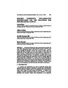
Indeed, it is quite safe to assume that output values of a simulation object (its position for example) are sampled values of a continuous signal. Therefore, extrapolation (in our case linear or quadratic based on the last 2 or 3 values) is expected to calculate a good enough value. Figure 3 shows the values seen through a mirror and extrapolation compared to the original values with a network latency of 100ms. We have found that for our different applications, this extrapolation enables correct calculations of the different simulation steps and provides the user with the illusion that the simulation is locally calculated as it can be seen on with the extrapolation of the sin x function which is very close in it’s values to the correct values (graphs superposed in figures 3 and 4).
Simulation 1 Calculation : CA Referential SOA
Output : position
"push" Simulation 2
Mirror of SOA
Output : position
"pull" Calculation : CB Referential SOB
Input : position
inria-00534145, version 1 - 8 Nov 2010
Figure 2: Typical exchange between two simulation objects in two different process
some level of synchronization to ensure a simulation step is not calculated if the values in mirrors are older (in simulated time) than a threshold because the current process is faster than the others. This threshold is an application level parameter thereafter called latency (because it is supposed to compensate for network latency).
2.3 Ensuring data consistency To ensure consistency between mirrors and their referentials two techniques are combined. The first is very straightforward as it implies than when a new output value is produced by a referential, it is stored in a buffer which is sent to the mirror at the end of the current simulation step. Nevertheless, this is not sufficient for continuity in the animation. Therefore, a simple extrapolation mechanism on the mirror side of the simulation is able to provide extrapolated values to any referential reading the output on the mirror. 15
original sinus a discontinuous quadratic sinus as seen trought network quadratic as seen trought network discontinuous signal discontinuous signal as seen trought network
10
5
As it can be seen in figure 3 outputs which produce discontinuous values are extrapolated with artifacts, which can be problematic for the numeric stability of the entities populating the virtual world. But this is a problem which can be simply solved by detecting such discontinuities and avoiding extrapolations based on values from both part of the discontinuous signal. Figure 4 shows the result of such an algorithm. As can be observed, the signal is only delayed, but its nature isn’t changed when it is seen through the network. 15
original sinus a discontinuous quadratic sinus as seen trought network quadratic as seen trought network discontinuous signal discontinuous signal as seen trought network
10
5
0
-5
-10 0
400
800
1200
1600
2000
2400
2800
3200
3600
4000
time in milliseconds
Figure 4: Comparison of real and estimated values: discontinuities detected and corrected
Network latency cannot be avoided. Nevertheless, its impact on the speed of a simulation can be avoided by using extrapolation in a way that doesn’t impact the nature of the signal as viewed through a mirror. Therefore, distribution of a collaborative virtual world can be done without much concern by the simulation object programmer.
0
2.4 GASP 3D Visualization -5
-10 0
400
800
1200
1600
2000
2400
2800
3200
3600
4000
time in milliseconds
Figure 3: Comparison of real and estimated values
Gasp provides a 3D visualization based on the SGI/Performer library, which is a particular simulation object. This object looks for all simulation objects which have a 3D representation and visualizes them. Animation of these object is possible because some of their outputs are associated by the visualization to dynamic coordinates in their geometry. In the case of a partially or completely distributed visualization, the visualization will
create the mirrors corresponding to the objects to visualize and therefore update the position and orientation according to the corresponding outputs of the object. As our visualization is a simulation object, there can be as many visualizations within the same simulation as needed. These different visualizations can be dispatched on different graphics workstations, in order to allow several users to see the same simulation. The users can choose interactively the viewpoint of the visualization, so several visualizations can also be placed on the same workstation in order to allow the end-user to see the same world with different viewpoints at the same time.
3.
INTERACTIONS WITH GASP
Using Gasp, there are several ways to interact with simulation objects : all of them use inputs and inputs of simulation objects.
inria-00534145, version 1 - 8 Nov 2010
3.1 Interaction Paradigm : Inputs, Outputs
it requires message communication between simulation objects. We are going to describe in the next section how we have implemented such dynamic interactors within Gasp and how this concept can be extended to add interaction capabilities to any simulation object.
3.2 Dynamical Interactions 3.2.1 Within a non-distributed universe As we have just said, it can be very interesting to allow the end-user to dynamically choose the simulation object he wants to interact with. Typically, such an interaction can occur with a 3D visualization and a particular device such as a mouse. The first stage consists in selecting interactively the object to interact with, in order to obtain its name. Then, assuming that we can find a particular simulation object of the universe from its name, we only have to explain to it, by method invocation, than some of its inputs have to be plugged to some of the outputs of a particular interactor, in order to perform a particular interaction.
Indeed, the communication between an end-user and a simulation object is only a particular case of communication between two simulation objects.
It seems quite easy, but it is not possible to realize it as simply with our referential/mirror distribution paradigm.
3.1.1 Low-level Interactors
3.2.2 Within a distributed universe
In the case of human-simulation object communication, a particular simulation object called interactor is associated to the end-user. So, the end user drives the interactor which produces outputs transmitted to another simulation object. In order to drive this interactor, the end-user needs a particular device (like a mouse for example) and a driver for this device, which is in the calculus part of the interactor. This part is then in charge of acquiring the low-level interactions events and data from the device and to translate them into correct Gasp outputs. This first category of interactor could be called low-level interactors because they are simply encapsulating a particular driver.
3.1.2 Composed Interactors Furthermore, we can create more complex interactor by combining existing interactors with other simulation objects. For example, an interactor could also have its own inputs in order to assist the end-user during the interaction. To let an end-user direct a camera that should stay in front of a car (to share the car driver point of view), it is possible to design a 6 Degrees of Freedom (DoF) composed interactor, using a 3 orientation DoF low-level interactor to let the end-user pilot the orientation, and using as inputs the 3 translation coordinates outputs of the car. The 3 orientation coordinates outputs of the 3 DoF interactor could even be a combination of the inputs from the user and of 3 other orientation coordinates inputs, which could be plugged to the corresponding outputs of the car. Even with such higherlever interactors, we are always very near from the notion of encapsulating drivers.
3.1.3 Dynamic Interactors For us, what is specific to an interactor is that it can be used to dynamically choose the simulation objects you want to interact with, and even which part of these objects. To realize such interactors is a little bit more difficult than realizing static ones, particularly in a distributed context :
The difficulty is here to access the referential we want to interact with, because as we did not chose a CORBA-like paradigm to perform the distribution of the simulation objects, we can not invoke methods so easily upon a simulation object. Indeed, this object may only be available in the current process through its mirror.
3.2.3 Interaction Paradigm Extended to Referentials and Mirrors So as we chose a referential/mirror with data-flow paradigm, all we can do is to send a message to the communicating object associated to the picked geometry (which is either a referential or a mirror). If this object is a referential, it will be able to interpret the message, if it is a mirror, it will send the message to its associated referential. Finally, the referential will receive it, and will be able to plug some of its inputs to the outputs of the interactor. The problem is then that if the referential and the interactor are not in the same process, the message will not be received at the same simulation step it has been sent, but at the next one, which induces latency. As the simulation object can refuse the interaction, it can then send a message to the interactor that will be received yet at another simulation step. If the simulation object accepts the interaction, it is then going to plug its inputs to the corresponding outputs of the interactor. Doing this, it is going to try to obtain these inputs in order to make a new calculation. At this stage, the new values of the interactor mirror outputs may not be present. The simulation object must wait these outputs to be initialized. So the interacted object will ignore the interactor until its mirror is initialized. We can minimize this delay if the outputs of the interactor have been correctly initialized. This last step assumes that it is possible to obtain, within the visualization object, the geometrical outputs (po-
inria-00534145, version 1 - 8 Nov 2010
Figure 5: Different visualizations with 2 workstations and 3 viewpoints
sition, orientation, . . . ) of the simulation object you want to interact with.
3.2.4 Dynamical Interaction with our Visualization At the first stage of the interaction, we have the following dynamical pick of a simulation object in order to obtain its name : • within a Performer window, the end-user clicks with the mouse “upon” the 3D visualization of a simulation object, • then a Performer picking is done with the mouse coordinates, • thus a Performer node subtree owning the 3D visualization of our simulation object is determined, • assuming the name of the simulation object is the same as the name of the higher level DCS (Dynamic Coordinate System) node of the subtree, we have obtained this very name. Then, as presented in a previous section, a message can be sent to the corresponding object, which will answer if it accepts the interaction. To quickly initialize the outputs of the interactor, the interactor’s referential is initialized with the coordinates of the DCS node associated with the simulation object geometry. This mechanism avoid a flicking move of the simulation object visualization toward an absurd position.
4.
BUILDING INTERACTIVE OBJECTS
As we have discussed before, interactors and simulation objects have to communicate by messages. So, in order to be interactive, a simulation object has to be able to respond correctly to messages from interactors. This is not very difficult, but it is sometimes quite repetitive when you want many simulation objects to be able to interact with the same
interactor, and it leads to code duplication, which should be avoided. Another problem is the complexity of implementing an object able to communicate with several interactors : you have to mix the code allowing communication with each interactor involved.
4.1 Inheritance from an Interactive Simulation Object A first solution would be to offer a particular simulation object class from which interactive simulation objects should inherit in order to be interactive. The main problem is that one class would not be enough, so that we should provide several such classes, one for each category of interactor. As our aim is to ease the task of the programmers by hiding most of the complexity of interaction mechanisms, we should ask them to inherit from one of these new classes in order to obtain an interactive simulation object. Then, there could be problems if we wanted an object to be able to communicate with another category of interactor than the one its inherited class is able to communicate with.
4.1.1 What About Older Simulation Objects ? Furthermore, our platform has now been operational for 8 years, and many simulation objects have been written during all this time, and they have not been designed for interaction. First, we whould have to modify their code, which is quite dangerous, because it could damage existing and well-functioning simulations. Second, there could be a lot of work to do to rewrite the code of all these objects in order to make them interactive, because there could be some incompatibilities between the old simulation objects and the new classes they would have to inherit from. So, we have to propose a solution that will not modify the existing code of simulation objects.
4.2 Interactive Simulation Objects Inherit from the Initial Ones In order to not modify the existing code, we have decided to make the interactive simulation objects inherit from the
initial simulation objects. We found two ways to realize it.
4.2.1 A First Solution: Multiple Inheritance So we have decided to provide several classes able to communicate with our interactors, without talking to the programmers about the interaction possibilities, in order to let them design, implement and use their simulation objects as usual, always with the aim not to disturb them. The classes that we provide that way are called interactive objects. As they must be able to communicate with other simulation objects in the same way as them, these classes have to inherit from the common simulation object ancestor class.
inria-00534145, version 1 - 8 Nov 2010
To obtain interactive simulation objects, we first proposed the following way to use our classes: by creating new simulation objects by multiple inheritance from the initial simulation object and from one or several interactive objects. As all our simulation objects, the corresponding classes inherit from the same ancestor class, there is diamond inheritance. We solve this problem with C++ virtual inheritance mechanism, which allows diamond inheritance but which is sometimes quite cumbersome to use. We obtain this way new simulation objects without modifying their initial code, which leads to two very interesting results : • the interactions can be provided by a HumanComputer Interaction specialist, without annoying the programmer of the initial simulation objects with such complex details as interaction or C++ multiple inheritance, • therefore this programmer can focus on his simulation problems, and he can easily make its initial simulation objects evolve, as with the inheritance mechanism all the modifications will be transmitted to the inherited simulation objects. The main drawback of this method is that we have to repeat the same work if many different classes of simulation objects have to be made interactive. So, we are now focusing on the possibility to use C++ template inheritance to ease this inheritance mechanism and then to obtain interactive simulation objects from noninteractive ones in a more generic way.
4.2.2 Template Inheritance for Interactive Simulation Objects As we said previously, C++ multiple inheritance is the hard way to offer interaction to our simulation objects because of the complexity of the mechanism involved, particularly when diamond inheritance can occur and when C++ virtual inheritance must be used. Of course, it is not a problem for an Object Oriented Language or C++ specialist, but most of Gasp users are not, because they focus first on physical or behavioral simulation, as they are experts about these simulation fields.
So we have try to simplify this approach and to replace it by genericity with C++ template inheritance. An interactive object class is now a C++ template class parameterized by the initial simulation object class you want to make interactive.
4.2.3 Examples For example suppose that Follower is the class of simulation objects able to follow another simulation object (and FollowerC its associated calculus class). We provide an interactive object template class MFollower (and MFollowerC its associated calculus class) which enables an object to be selected and then to follow the position of the mouse until it is deselected. It is then immediate to obtain a simulation object that will follow another object until it will be selected by the end-user. It will then follow the mouse, and at last when it will be deselected, it will go on following its initial target. This is obtained with a particular instantiation of our Follower class as shown figure 6. The MFollower class main features are the creation of its associated calculus (templated by the initial calculus class), and the explanation of how it manages the events in order to communicate with an interactor. The MFollowerC calculation class will be able to plug the inputs of its associated MFollower class to the outputs of an interactor. The most interesting method of this class is the calculate one, which calls its inherited calculate method (which calculate the position of the object, and maybe many other things) and then try to follow the interactor by updating the position of the object. What is interesting with our approach is that it is now very easy, to a Gasp’user point of view, to make his simulation objects interactive. Another important thing is that it is easy to provide the same way many categories of interactive objects, here again with C++ template inheritance. Suppose for example that we do not want an interactive object to go to far from the position it would have if it was not interactive. To obtain such an interactive behavior, we should have to modify the calculate method of the MFollower class. It can be done easily here again with C++ template inheritance, with two new classes: LMFollower and LMFollowerC (the “L” stands for “limited”). The important thing here is to ensure that this new calculate method makes a call to the ICalculus corresponding method, then stores the position obtained, then obtains the position reached with the interactor, and then calculates if this position can be reached. If not, a new position must be calculated and set to the position field of the associated simulation object as shown figure 7. We can notice that the instantiation of such an interactive object is always as simple as in the previous case with no constraint about the position.
4.2.4 Drawback of our method Our template inheritance method relies upon the existence of a particular field in the inherited class : position in the case of the exemple used to illustrate the method as in figure 7. This method of interaction with the inherited class by direct access to the particular attribute you want
template class MFollower : public IObject { public : MFollower () ; virtual ~MFollower () ; virtual Calculus * createCalculus () { return new MFollowerC () ; } virtual void manageEvt () ; ... // other methods ... } ;
inria-00534145, version 1 - 8 Nov 2010
template class MFollowerC : public ICalculus { public : MFollowerC () ; virtual ~MFollowerC () ; virtual void calculate () { ICalculus::calculate () ; interactorFollow () ; } virtual void interactorFollow () ; virtual void plugInteractor (...) ; virtual void unplugInteractor () ; protected : Position proposedPosition ; } ; ... SO so = new MFollower ; ...
Figure 6: Follower
C++ Instantiation of an Interactive
to control within the new template subclass is not a very good one. Indeed, in order to control another attribute of the same type, you have to create another C++ template class, very similar to this first class : this clearly leads to code duplication.
5.
EXAMPLES OF INTERACTIONS
Here are some examples of interaction within GASP.
5.1 Visualization Driven Interactions All the interactions driven by a device managed by a 3D visualization are similar to the mouse driven interaction previously discussed. In these cases, the calculus part of the visualization simulation object has to manage the device in order to provide the corresponding outputs. The concerned devices are the mouse, the keyboard, dial boxes, and every particular device the 3D visualization is able to manage.
5.2 Interactions with other devices A dedicated simulation object must be provided for the other devices. The associated calculus object is then in charge of acquiring the data from the device and of updating the outputs of the simulation object. We are going to present here such an interaction. The device we are interested in is a 3D LEDs motion capture device SM3D 1000 from SAGEIS. It is composed of 3 linear cameras tracking a set of LEDs in a 3D bounded volume. In our case, this system is able to provide the 3D position
template class LMFollower : public MFollower { public : LMFollower () ; virtual ~LMFollower () ; virtual Calculus * createCalculus () { return new LMFollowerC () ; } } ; template class LMFollowerC : public ICalculus { public : LMFollowerC () ; virtual ~LMFollowerC () ; virtual void calculate () { ICalculus::calculate () ; initialPosition = position ; interactorFollow () ; proposedPosition = position ; ... // calculation of the ... // final position position->set (finalPosition) ; } virtual void interactorFollow () ; protected : Position initialPosition ; Position finalPosition ; } ; ... SO so = new LMFollower ; ...
Figure 7: C++ Instantiation of an Interactive Limited Follower
of four LEDs on a RS232 PC serial port. So, in order to provide these four 3D positions to simulation objects that would be interested in them, we have developed a particular simulation object with the four appropriate outputs, and with a calculus object able to read data from a RS232 SGI serial port. Such a device is very interesting for immersive interaction within 3D worlds. For example, figures 8, 9, 10 and 11 are snapshots of a particular interaction with this device (the displays are using stereovision, explaining the poor quality of the visuals). Here only two LEDs are used in order to simulate a 3D mouse. One LED is used in order to move the 3D mouse cursor, represented by a star. We can see Figure 8 the end-user approaching this cursor from a 3D simulation object : a sphere. When this cursor is near enough from a simulation object, the end-user can approach the second led from the first one in order to “click”, and then, in this very case, to assign the position of the simulation object to the position of the LED. This click has been done between figure 8 and figure 9. The end-user can then move the selected object to a particular position, and after that he can release it by doing another click as shown figure 10. The end user can then click upon another simulation object to move it as shown figure 11.
inria-00534145, version 1 - 8 Nov 2010
Figure 8: Interaction with 2 LEDs to obtain a 3D mouse : the beginning
Figure 10: Interaction with 2 LEDs to obtain a 3D mouse : the second click to release the object
Figure 9: Interaction with 2 LEDs to obtain a 3D mouse : just after the first click to grasp the object
Figure 11: Interaction with 2 LEDs to obtain a 3D mouse : going on with another object
5.3 Multi-User Distributed Interactions
The LEDs driven cooperation application is sharable between several users with LEDs and other users in front of their own workstations, as shown figure 13.
With our input/output paradigm for simulation objects, it is quite natural to allow several simulation objects outputs to be plugged to some inputs of a particular simulation object, and then to allow them to cooperate in the driving of this object, assuming it is able to merge all the inputs to obtain a pertinent resulting input. As an interactor is a particular simulation object, several end-users can collaborate this way in the driving of any simulation object : • from a high level, when each end-user drives only its own simulation object : only the global simulation is affected by the cooperation, • to a very low level, when several users provides outputs for the inputs of a thus shared simulation object. A classical mouse driven cooperation example is shown figure 12.
6. ONGOING WORK 6.1 Template Inheritance Rather than allowing to take control of an inherited field directly in the derivated template class (cf 4.2.4), it would be better to use an appropriate structure. Therefore we have worked on a way to offer to the template subclass the possibility to act upon a particular category of attributes, which can be selected using their name (as a string). This way, it is possible to act upon restricted parameters of a simulation object instance of the inherited class, for example only its inputs, outputs or control parameters. We now have to provide a new category of parameters that could be dedicated to the storing of the internal state of a simulation object: we think for exemple about the notion of state parameter.
inria-00534145, version 1 - 8 Nov 2010
Figure 12: Mouse driven cooperation between two different users
level interactors allowing us to think about new interaction paradigms, such as the 3D mouse interactor made with only two LEDs. So we now have to focus on those new interaction paradigms in order to create new 3D “lightweight” logical interactive devices, which could be obtained either with physical devices such as LEDs, or with a combination of already existing devices. The main interest of such devices would be that they could be software configured, without having any trouble with the physical drivers, assuming such drivers would have been provided once.
6.4 A Second Distribution Paradigm : Replicated Objects Figure 13: Cooperation between several users
6.2 Multi-User Interactions We have said that when several (distributed or not) users wanted to interact with the same object, this object could have to be able to merge all of the inputs to obtain a pertinent resulting input, for example in the case of several users wanting to act on the same inputs of a simulation object. If this object is not able to do this, it is quite easy to plug its inputs to the outputs of a merging simulation object which will be able to provide the adapted outputs. We can imagine this way some useful merging objects as min, max, mean, ... We now have to provide all these “of the shelf” merging simulation objects in order to ease the programmers task for simultaneous multi-user interaction upon the same object.
6.3 Higher Level Interactions As shown in this paper, Gasp is now able not only to accept any particular device with its adapted driver in order to interact with a simulation object, but also to offer higher
While distribution of virtual entities or interactors is natural and effective with the mirror/referential paradigm, distributing a world database so that entities can find out about their surroundings has proven difficult. The reason is that it is difficult to encapsulate a world database in a simulation object because either the outputs of such an object would have to be adapted to their reader or a complex event and message protocol would have to be adopted to be able to get to pertinent information in the database with very poor performance when distributed. Therefore, a new class of objects has been introduced in Gasp: replicated objects. These objects aren’t owned by a process of the simulation but are created in any process which owns referentials that need the information they produce. Because their are created in the same process, method invocations of member functions can be used to interact with those objects. Nevertheless, replicated objects can still interact with other objects through the general mechanism used by other objects. At the writing of this paper, no specific mechanism as been provided to help the programmer keep the different copies of a replicated object coherent. We anticipate they aren’t needed in many cases. Indeed, the reason replicated ob-
jects where introduced was to provide a more convenient and efficient way of reading the data they produced. Data collection and update by the replicated objects should still be performed by reading the inputs of the object. Therefore, all copies of the replicated object will update their database by reading the same data, thus ensuring data coherence between the copies.
7.
CONCLUSION
In this paper, we have presented how interactors are integrated in Gasp and how that introduction enables multiple configurations for multi-user interaction. We have also presented a generic approach to build interactive objects from existing objects. Furthermore, as Gasp was at first designed to distribute the calculation weight of animating autonomous agents, multiple users can collaborate in these interactions. We believe that the concepts involved to build collaborative virtual environments with Gasp are simple enough to enable a great number of programmers to participate in the construction of virtual worlds where possible collaboration is compatible with complexity, at the geometry level as well as at the animation level.
inria-00534145, version 1 - 8 Nov 2010
8.
REFERENCES
[1] C. Carlsson and O. Hagsand. DIVE — A platform for multi-user virtual environments. Computers and Graphics, 17(6):663–669, Nov.–Dec. 1993. [2] D. Margery, B. Arnaldi, and N. Plouzeau. A general framework for cooperative manipulation in virtual environments. In M. Gervautz, A. Hildebrand, and D. Schmaltsieg, editors, Virtual Environments ’99, pages 169–178. Eurographics, Springer, 1999. [3] S. Ghee and J. Naughton-Green. Programming virtual worlds. SIGGRAPH’94 Course, (17), 1994. [4] C. Greenhalgh and S. Benford. MASSIVE: A distributed virtual reality system incorporating spatial trading.
In Proceedings of the 15th International Conference on Distributed Computing Systems (ICDCS’95), pages 27–35, Los Alamitos, CA, USA, May30 June–2 1995. IEEE Computer Society Press. [5] C. Just, A. Bierbaum, A. Baker, and C. Cruz-Neira. Vr juggler: A framework for virtual reality development. In Proceedings of the 2nd International Immersive Projection Technology Workshop, 1998. [6] R. Lea, Y. Honda, K. Matsuda, and S. Matsuda. Community place: Architecture and performance. In R. Carey and P. Strauss, editors, VRML 97: Second Symposium on the Virtual Reality Modeling Language, New York City, NY, Feb. 1997. ACM SIGGRAPH / ACM SIGCOMM, ACM Press. ISBN 0-89791-886-x. [7] M. Macedonia. A Network software Architecture For Large Scale Virtual Environnements. PhD thesis, Naval Postgraduate School, Monterey, California, 1995. [8] M. Macedonia, M. Zyda, D. Pratt, P. Barham, and S. Zeswitz. Npsnet: A network software architecture for large scale virtual environments. Presence, 3(4):265–287, 1994. [9] S. Donikian, A. Chauffaut, T. Duval, and R. Kulpa. Gasp: from modular programming to distributed execution. In Computer Animation’98, IEEE, Philadelphia, USA, pages 79–87, june 1998. [10] D. Snowdon and A. West. AVIARY: Design issues for future large-scale virtual environments. Presence, 3(4):288–308, 1994. [11] T. Duval and D. Margery. Using gasp for collaborative interactions within 3d virtual worlds. In Proceedings of the Second International Conference on Virtual Worlds (VW’2000), Paris, France, july 2000. Springer LNCS/AI.