Chapter 3 Defining Models and Processes to Support Policy Analysis ..... To all my colleagues (and friends) at the Energy Systems Research Unit for the ...... interest rates, and the inflation rate to determine how each of these changes affects .... simulation is key to evaluating critical building performance issues, such as ...
BUILDING PERFORMANCE SIMULATION: A TOOL FOR POLICYMAKING
Drury Browne Crawley, IV, B. Arch.
A thesis submitted for the Degree of Doctor of Philosophy
Energy Systems Research Unit Department of Mechanical Engineering University of Strathclyde Glasgow, Scotland, UK
December 2008
Copyright Declaration The copyright of this thesis belongs to the author under the terms of the United Kingdom Copyright Acts as qualified by University of Strathclyde Regulation 3.50. Due acknowledgement must always be made of the use of any material contained in, or derived from, this thesis.
ii
Table of Contents Abstract Dedication Abbreviations Figures Tables Chapter 1 The Power of Building Simulation as a Policy Tool 1.1 1.2 1.3 1.4 1.5 1.6 1.7
Importance of Simulation ............................................................................................. 1-1 What is Simulation? ...................................................................................................... 1-2 Modelling Buildings ..................................................................................................... 1-3 Energy Use in Buildings ............................................................................................... 1-4 Building Performance Simulation ................................................................................ 1-5 Simulation as a Tool for Building Policy ..................................................................... 1-8 References..................................................................................................................... 1-9
Chapter 2 Building Performance Simulation in Policymaking 2.1 2.2 2.3 2.4 2.5 2.6 2.7 2.8
Introduction................................................................................................................... 2-1 Evaluation of Building Energy Standards .................................................................... 2-2 Building Model, Building Stock, and Utility Incentives .............................................. 2-4 Climate Data in Building Performance Modeling ........................................................ 2-8 Modeling Climate Change and Urban Heat Islands ..................................................... 2-9 Data Issues in Multi-Building Studies ........................................................................ 2-11 Summary ..................................................................................................................... 2-13 References................................................................................................................... 2-15
Chapter 3 Defining Models and Processes to Support Policy Analysis 3.1 Introduction................................................................................................................... 3-1 3.2 Developing Models to Support Thermal Envelope Analysis in a Building Energy Code........................................................................................... 3-5 3.2.1 Background ....................................................................................................... 3-5 3.2.2 Review of Standard 90.1 Envelope Load Correlations ..................................... 3-6 3.2.3 Concerns about Using 90.1 Envelope Correlations for NECB ......................... 3-6 3.2.4 Predicted Heating and Cooling Loads from Envelope Correlations ................. 3-7 3.2.5 New Prototypical Building Model for Envelope Correlations .......................... 3-8 3.2.6 Predicted Heating and Cooling Loads using New Prototypical Building Model .......................................................................................... 3-9 3.2.7 Design of Parametric Analyses for Envelope Correlations ............................. 3-14 3.2.8 Development of Parametric Simulation Routines ........................................... 3-19
iii
3.3 Evaluating Performance Levels for Envelope Incentives in a New Building Construction Program .......................................................................... 3-19 3.3.1 Definition of Baseline Building Model ........................................................... 3-21 3.3.2 Design of the Analysis for the Envelope Incentives ....................................... 3-21 3.4 Developing Models and Data Sets to Support Development of a National Voluntary Program for Existing Building Retrofits ............................. 3-24 3.4.1 Parametric Energy Simulation of ESB Staged Implementation Approach ..... 3-26 3.4.2 Creating Energy Simulation Databases for Envelope Upgrades and Chiller Upgrades ............................................................................... 3-33 3.4.3 Which Weather Data to Use? .......................................................................... 3-37 3.5 Developing Building Models and Climate Data to Support Impact Analysis of Climate Change and Urban Heat Islands ......................................... 3-38 3.5.1 What are the Potential Impacts on the Built Environment? ........................... 3-40 3.5.2 A Bottom-Up Model for Evaluating Impacts of Climate Change ................... 3-41 3.5.3 Selecting Weather Sources, Climate Regions, and Locations ......................... 3-42 3.5.4 Representing the Climate Change Scenarios................................................... 3-49 3.5.5 Representing the Urban Heat Island................................................................ 3-53 3.5.6 Representing Building Stock ........................................................................... 3-55 3.5.7 Design of the Simulation Study ...................................................................... 3-58 3.6 References................................................................................................................... 3-69
Chapter 4 Using Building Simulation to Define and Evaluate Building Energy Standards 4.1 Introduction................................................................................................................... 4-1 4.2 Defining Equivalent Performance Relationships for Building Envelopes in an Energy Code ..................................................................................................... 4-1 4.2.1 Envelope Performance Data Set ........................................................................ 4-2 4.2.2 Creating Envelope Performance Correlations from the Data Set ...................... 4-3 4.2.3 Conclusions ....................................................................................................... 4-6 4.3 Defining Envelope Incentives for An Electric Utility .................................................. 4-7 4.3.1 Energy Performance of Envelope Options ........................................................ 4-7 4.3.2 Economic Performance of Envelope Options ................................................... 4-8 4.3.3 Conclusions from the Evaluation of Potential Envelope Incentives ................. 4-8 4.4 Energy and Economic Evaluation of Existing Building Retrofits ................................ 4-9 4.4.1 Results of Parametric Energy Simulation of ESB Staged Implementation Approach ................................................................................................... 4-9 4.4.2 Simulation Results for Detailed Envelope Upgrades ...................................... 4-27 4.4.3 Chiller Upgrade Results .................................................................................. 4-36 4.4.4 Weather Data Comparison Results ................................................................. 4-36 4.4.5 Conclusions from ESB Analyses .................................................................... 4-46 4.5 Summary ..................................................................................................................... 4-47 4.6 References................................................................................................................... 4-47
Chapter 5 Evaluating Climate Change and Heat Islands Impacts on Buildings 5.1 5.2 5.3 5.4 5.5
Introduction.................................................................................................................. 5-1 Annual Energy Performance Results ........................................................................... 5-2 Monthly End-Use Energy Performance Results .......................................................... 5-4 Variation in Energy Performance Results Due to Different Weather Years ............... 5-8 Potential Energy Performance Impacts of Heat Islands and Climate Change Scenarios for the Small Office Building ............................................................. 5-18
iv
5.6 Summary ..................................................................................................................... 5-20 5.7 References................................................................................................................... 5-22
Chapter 6 Summary and Conclusions 6.1 6.2 6.3 6.4
Research Summary ....................................................................................................... 6-1 Policy Implications of the Simulation Studies .............................................................. 6-3 Conclusions .................................................................................................................. 6-5 Future Work ................................................................................................................ 6-11
Appendix A Weather Data and Data Sets for Envelope Correlations ............................................................................... A-1 Appendix B Prescriptive Envelope Requirements and Results of Evaluation of Utility Incentives ............................. B-1 Appendix C Simulation Results for the Energy Star Buildings Analyses .......................................................................... C-1 Appendix D Simulation Results for the Evaluation of Potential Climate Change and Heat Islands Impacts ................. D-1
v
Abstract Building energy and environmental performance simulation programs have the capability to evaluate a wide range of responses to external stimulus. Typically, these software tools are used by practitioners evaluating individual building design or retrofits. Other uses for building simulation include overheating prediction, heating and cooling equipment design, evaluation of alternate technologies (energy efficiency and renewable energy), regulatory compliance or, more recently, integrated views of multiple simulation results.
The most powerful use for simulation, however, lies in the ability to look beyond individual buildings to support policy decision making, including mandatory rule makings such as standards and codes, voluntary financial incentive programs such as those used by utilities to incentivize reduced power demand, evaluating and identifying opportunities for voluntary building energy efficiency programs, or to look at potential impacts related to broader policy levels such as heat island and climate change. Simulation, when coupled with building models that represent a range of building types and locations, can represent a portion of or the entire building stock.
This thesis researches how building energy simulation can be used to guide, define, determine, and support decisions by policy makers. Four research studies demonstrate how building performance simulation informs and defines building-related policy for standards, utility incentive programs, energy-efficiency programs, and the determination of climatic influence and sensitivity on building operating performance. These studies show how decision-makers have used building performance simulation to craft voluntary and mandatory programs for building energy efficiency. From these four studies, a generalized framework of building-related policy research is derived with three major categories: research and policy focus, building model, and analysis structure and output data.
vi
Dedication To my wife, Anne, with thanks for the support, love, belief that it could and would be finally done, and patience for all the long days and nights when I was ‘working on my PhD’.
To Becca and Alex, for sort of understanding that Dad would one day be finished and have more time for them. (And for bringing joy into our lives.)
To my parents for a lifetime of support and belief in me.
To all my colleagues (and friends) at the Energy Systems Research Unit for the encouragement and friendship all these years—stimulating conversations, hill walks, sailing, and outings to the pub. Special thanks to Professor Joe Clarke, advisor extraordinaire and friend; to Jon Hand for unceasing hospitality and a willing ear for half-baked ideas; and to Paul Strachan for insightful review which helped point out clear paths forward. And finally, thanks to Professor Jon Wright of Loughborough University, for careful, perceptive review which significantly improved the final thesis.
vii
Abbreviations AEDG Ag Aw AIA ASHRAE BERR BEPS BIM BOMA CAD CBECS CEC CFC CFM CGCM2 CICES CO2 COP CSIRO2 CSV CTZ2 CV CWEC DB DP DTI EDEM EFLH EIA ESB FWR GCM HadCM3 HVAC IESNA IPCC IRR IWEC LBL LCC NBECS NCDC NECB NOx NRC NRCan NREL NSRDB
Advanced Energy Design Guide glazing area wall area American Institute of Architects American Society of Heating, Refrigerating, and Air-conditioning Engineers UK Department for Business Enterprise & Regulatory Reform Building Energy Performance Standards building information model Building Owners and Managers Association International computer-aided design Commercial Building Energy Consumption Survey California Energy Commission chlorofluorocarbon cubic feet per minute Canadian General Circulation Model 2 Commercial and Institutional Consumption of Energy Survey carbon dioxide coefficient of performance Commonwealth Scientific and Industrial Research Organization CSIRO2 GCM comma-separated value California Thermal Zone 2 constant volume Canadian Weather for Energy Calculations dry bulb dew point UK Department of Trade and Industry ESRU Domestic Energy Model equivalent full-load hours Energy Information Administration Energy Star Buildings fenestration-to-wall ratio general circulation model Hadley Circulation Model 3 heating, ventilating, and air-conditioning Illuminating Engineering Society of North America Intergovernmental Panel on Climate Change internal rate of return International Weather for Energy Calculations Lawrence Berkeley National Laboratory life-cycle cost Nonresidential Building Energy Consumption Survey National Climatic Data Center National Energy Code for Buildings nitrous oxide National Research Council of Canada Natural Resources Canada National Renewable Energy Laboratory National Solar Radiation Data Base
viii
PCM PSZ QA RH SAMSON SBEM SC SO2 SP41 SSPC TMY TMY2 TRY UA Ug US DOE US EPA USGBC Uw VAV VSD WC WYEC WYEC2 WWR XML
National Center for Atmospheric Research GCM packaged single-zone quality assurance relative humidity Solar and Meteorological Surface Observation Network Simplified Building Energy Model shading coefficient sulfur dioxide ASHRAE Special Project 41 Standing Standard Project Committee Typical Meteorological Year Typical Meteorological Year 2 Typical Reference Year U-value times area U-value of glazing U. S. Department of Energy U. S. Environmental Protection Agency U. S. Green Building Council U-value of wall variable air volume variable speed drive water column Weather Year for Energy Calculations Weather Year for Energy Calculations 2 window-to-wall ratio extensible markup language
ix
Figures Figure 1-1. Percentage Energy Use by Sector for the World and Selected Countries .......... 1-5 Figure 2-1. Annual Average Outdoor Temperature and Predicted Indoor Mean Air and Radiant Temperature, °C, by Zone in Chicago, Illinois, USA............................ 2-10 Figure 3-1. Coil Loads for East Orientation ....................................................................... 3-10 Figure 3-2. Coil Loads for the North Orientation ............................................................... 3-11 Figure 3-3. Coil Loads for the South Orientation ............................................................... 3-12 Figure 3-4. Coil Loads for the West Orientation ................................................................ 3-13 Figure 3-5. Diagram of Four-Zone DOE-2 Building Model .............................................. 3-14 Figure 3-6. DOE-2.1E Results, Ottawa, South Orientation, 21.5 W/m2 ............................. 3-15 Figure 3-7. Global Annual Average Temperature Change Predicted by Four Major Global Climate Models ................................................................................................... 3-39 Figure 3-8. Commercial Building Energy End-Uses in the United States (EIA 2002) and Europe (EC 2000) ............................................................................................... 3-42 Figure 3-9. Washington, D. C., Summed Heating and Cooling Degree Days Ranked from Highest to Lowest ............................................................................................... 3-47 Figure 3-10. Washington, DC, Energy End-Use Consumption for 550 m2 Office Building ................................................................................................... 3-47 Figure 3-11. Resolute, Nunavut, Canada, Energy End-Use Consumption for 550 m2 Office Building .............................................................................................................. 3-48 Figure 3-12. San Juan, Puerto Rico, Energy End-Use Consumption for 550 m2 Office Building .............................................................................................................. 3-48 Figure 3-13. Example TMY2 and Climate Change Scenario Dry Bulb Temperatures for December in Washington, DC ............................................................................ 3-56 Figure 3-14. Example TMY2 and Heat Island Dry Bulb Temperatures for April in Washington, DC.................................................................................................. 3-56 Figure 3-15. Schematic of Small Office Building .............................................................. 3-64 Figure 3-16. Schematic of Low-Energy Building............................................................... 3-64 Figure 4-1. DOE-2.1E Results, Ottawa, Ontario, Canada, South Orientation, 21.5 W/ft2 ... 4-4 Figure 4-2. Predicted Cooling Energy for Correlation v. DOE-2.1E Simulations for East Orientation in Ottawa ............................................................................................ 4-5 Figure 4-3. Predicted Heating Energy for Correlation v. DOE-2.1E Simulations for East Orientation in Ottawa ............................................................................................ 4-5 Figure 4-4. Energy End-Use by Stage for Mid-Rise Office Building with Gas Heat in Washington, D.C................................................................................................. 4-19 Figure 4-5. Comparison of Energy End-Uses for Existing Buildings and Energy Star Buildings Upgrade for the Three Office Building Sizes in Washington, D.C. ... 4-19 Figure 4-6. Comparison of Existing Buildings and Energy Star Building Upgrades for Eight Locations ................................................................................................... 4-20 Figure 4-7. Annual Energy Cost Savings for Adding 13 mm Roof Insulation with Constant Volume Reheat and High Lighting (24.75 W/m2) in Four Locations ................. 4-30 Figure 4-8. Annual Energy Cost Savings for Adding 13 mm Roof Insulation in Washington, D.C. ........................................................................................... 4-31 Figure 4-9. Cost-Effectiveness Results for Roof Insulation Upgrades with CV Reheat System and High Lighting in Washington, D.C. ................................................ 4-31 Figure 4-10. Cost-Effectiveness Results for Roof Insulation Upgrades with CV Reheat System and Low Lighting in Washington, D.C. ................................................. 4-32
x
Figure 4-11. Cost-Effectiveness Results for Roof Insulation Upgrades with VAV Reheat System and High Lighting in Washington, D.C. .................................... 4-32 Figure 4-12. Cost-Effective Results for Roof Insulation Upgrades with VAV Reheat System and Low Lighting in Washington, D.C. ................................................. 4-33 Figure 4-13. Effect of Roof Color and System Type on Roof Insulation Upgrade CostEffectiveness for Washington, D.C..................................................................... 4-33 Figure 4-14. Effect of Internal Loads (Lighting) and System Type on Roof Insulation Upgrade Cost-Effectiveness for Washington, D.C. ............................................ 4-35 Figure 4-15. Effect of Fan Motor Pulley Change-out and System Type on Roof Insulation Upgrade Cost-Effectiveness for Washington, D.C. ........................... 4-35 Figure 4-16. Chiller Upgrade Simulation Results for All-Electric Mid-Rise Office Building in Washington, D.C.............................................................................. 4-37 Figure 4-17. Annual End-Use Energy Consumption for a Gas-Heated Low-Rise Office Building in Washington, D.C.............................................................................. 4-39 Figure 4-18. Annual Energy Costs by Year for a Gas-Heated Office Building in Washington, D.C................................................................................................. 4-39 Figure 4-19. Comparison of Annual Energy Consumption for Weather File Types and SAMSON Weather Data in Washington, D.C. ................................................... 4-42 Figure 4-20. Comparison of Annual Energy Costs for Weather File Types and SAMSON Weather Data in Washington, D.C. .................................................................... 4-42 Figure 4-21. Comparison of Annual Peak Loads in Washington, D.C. .............................. 4-43 Figure 5-1. Annual Site Energy End-Use Consumption, in MJ/m2, in Washington, DC, USA for Standard, Developing, and Low-Energy Buildings Using Typical Year, Climate Change Scenarios, and Heat Island Cases Using Typical Weather Data .............. 5-3 Figure 5-2. Annual Source Energy End-Use Consumption, in MJ/m2, in Washington, DC, USA for Standard Building and Four Climate Change Scenarios Using Typical Weather ................................................................................................................. 5-3 Figure 5-3. Annual Source Energy End-Use Consumption, in MJ/m2, in Washington, DC, USA for Standard Building and High and Low Heat Island Cases Using Typical Weather ................................................................................................................. 5-4 Figure 5-4. Monthly Source Energy End-Use Consumption, in MJ/m2, in Washington, DC, USA for Standard Building and Four Climate Change Scenarios Using Typical Weather ................................................................................................................. 5-6 Figure 5-5. Monthly Source Energy End-Use Consumption, in MJ/m2, in Washington, DC, USA for Developing Building and Four Climate Change Scenarios Using Typical Weather ................................................................................................................. 5-6 Figure 5-6. Monthly Source Energy End-Use Consumption, in MJ/m2, in Washington, DC, USA for Standard Building and High and Low Heat Island Cases Using Typical Weather ................................................................................................................. 5-7 Figure 5-7. Monthly Source Energy End-Use Consumption, in MJ/m2, in Washington, DC, USA for Low Energy Building and High and Low Heat Island Cases Using Typical Weather .................................................................................................... 5-7 Figure 5-8. Monthly Source Energy End-Use Consumption, in MJ/m2, in Washington, DC, USA for Developing Building and High and Low Heat Island Cases Using Typical Weather ................................................................................................................. 5-8 Figure 5-9. Monthly Source Energy End-Use Consumption, in MJ/m2, in San Juan, Puerto Rico for Standard Building and Four Climate Change Scenarios Using Typical Weather ................................................................................................................. 5-9 Figure 5-10. Monthly Source Energy End-Use Consumption, in MJ/m2, in San Juan, Puerto Rico for Low Energy Building and Four Climate Change Scenarios Using Typical Weather ................................................................................................................. 5-9
xi
Figure 5-11. Monthly Source Energy End-Use Consumption, in MJ/m2, in San Juan, Puerto Rico for Standard Building and High and Low Heat Island Cases Using Typical Weather ............................................................................................................... 5-10 Figure 5-12. Monthly Source Energy End-Use Consumption, in MJ/m2, in San Juan, Puerto Rico for Low Energy Building and High and Low Heat Island Cases Using Typical Weather ............................................................................................................... 5-10 Figure 5-13. Monthly Source Energy End-Use Consumption, in MJ/m2, in Resolute, Nunavut, Canada for Standard Building and Climate Change Scenarios Using Typical Weather .................................................................................................. 5-11 Figure 5-14. Monthly Source Energy End-Use Consumption, in MJ/m2, in Resolute, Nunavut, Canada for Low Energy Building and Climate Change Scenarios Using Typical Weather .................................................................................................. 5-11 Figure 5-15. Monthly Source Energy End-Use Consumption, in MJ/m2, in Resolute, Nunavut, Canada for Standard Building and Heat Island Cases Using Typical Weather ............................................................................................................... 5-12 Figure 5-16. Monthly Source Energy End-Use Consumption, in MJ/m2, in Resolute, Nunavut, Canada for Low Energy Building and Heat Island Cases Using Typical Weather ............................................................................................................... 5-12 Figure 5-17. Percent Change in Annual Energy Consumption from the Typical Weather Data for Climate Change and Heat Island Cases in Washington, DC, USA ............... 5-19 Figure 5-18 Percent Change in Annual Energy Consumption from the Typical Weather Data for Climate Change and Heat Island Cases in San Juan, Puerto Rico ................ 5-19 Figure 5-19. Percent Change in Annual Energy Consumption from the Typical Weather Data for Climate Change and Heat Island Cases in Resolute, Nunavut, Canada ........ 5-20
xii
Tables Table 3-1. Key Attributes of the Four Studies ...................................................................... 3-4 Table 3-2. Heat Loss/Gain Parametric Cases ..................................................................... 3-17 Table 3-3. Solar Gain Parametric Cases ............................................................................ 3-18 Table 3-4. Internal Gain Parametric Cases ......................................................................... 3-18 Table 3-5. Baseline Fenestration ........................................................................................ 3-22 Table 3-6. Baseline Wall and Roof Overall U-Values........................................................ 3-22 Table 3-7. Fenestration Options.......................................................................................... 3-22 Table 3-8. Fenestration Costs ............................................................................................. 3-23 Table 3-9. Wall Insulation Costs ........................................................................................ 3-24 Table 3-10. Roof Insulation Costs ...................................................................................... 3-24 Table 3-11. Office Building Stock Categories .................................................................... 3-28 Table 3-12. Office Building Stock Categories Characteristics ........................................... 3-28 Table 3-13. Three Existing Office Building Models .......................................................... 3-29 Table 3-14 Base Case Assumptions: Building Equipment and Systems ............................ 3-29 Table 3-15. Stage 5 Upgrades by Building Size and Location ........................................... 3-34 Table 3-16. Upgrade Costs by Stage................................................................................... 3-29 Table 3-17. Köppen Climate Classification System ........................................................... 3-44 Table 3-18. Selected Locations and Climate Characteristics .............................................. 3-45 Table 3-19. Available and Selected Weather Years for the 25 Locations .......................... 3-50 Table 3-20. Weather File Type and Years with Highest and Lowest Energy..................... 3-51 Table 3-21. Commercial Building Floor Area, Number of Buildings, Energy Consumption and Other Characteristics by Principal Building Activity ............ 3-59 Table 3-22. Office, Warehouse, and Retail Sectors Subdivisions ...................................... 3-60 Table 3-23. Definitions of Eight Commercial Building Prototypes Based on CBECS ...... 3-60 Table 3-24. Base Standard (Standard 90.1-2004) Wall, Roof, and Fenestration Envelope Requirements ...................................................................................... 3-61 Table 3-25. Developing Standard Wall, Roof, and Fenestration Envelope Assumptions........................................................................................................ 3-62 Table 3-26. Low-Energy Case Wall, Roof, and Fenestration Envelope Assumptions ....... 3-63 Table 3-27. Low-Energy Case Photovoltaic System Tilt Angles ....................................... 3-65 Table 3-28. Base Standard HVAC and SWH Equipment Efficiency ................................. 3-65 Table 3-29. Developing Standard HVAC and SWH Equipment Efficiency ...................... 3-65 Table 3-30. Low-Energy Building HVAC and SWH Equipment Efficiency ..................... 3-65 Table 4-1. Simulation Results for Wall Insulation Options in Toronto with 21.5 W/m2 Internal Loads and 0.4 FWR....................................................... 4-7 Table 4-2. Simulation Results for Roof Insulation Options in Toronto with 21.5 W/m2 Internal Loads and 0.4 FWR....................................................... 4-7 Table 4-3. Simulation Results for Fenestration Options in Toronto with 21.5 W/m2 Internal Loads and 0.4 FWR....................................................... 4-8 Table 4-4. Energy and Economic Results for Wall Insulation Options .............................. 4-10 Table 4-5. Energy and Economic Results for Roof Insulation Options.............................. 4-11 Table 4-6. Energy and Economic Results for Fenestration Options for Ottawa ................. 4-12 Table 4-7. Energy and Economic Results for Fenestration Options for Sault Ste. Marie .. 4-13 Table 4-8. Energy and Economic Results for Fenestration Options for Schefferville........ 4-14 Table 4-9. Energy and Economic Results for Fenestration Options for Toronto ............... 4-15 Table 4-10. Energy and Economic Results for Fenestration Options for Windsor ............ 4-16 Table 4-11. Three Existing Office Building Models .......................................................... 4-18
xiii
Table 4-12. DOE-2.1E Simulation Results for Gas-Heated Existing Low-Rise Office Building (4,461 m2, 3 floors) .............................................................................. 4-18 Table 4-13. Energy Performance of the Five Stages for the Mid-Rise Office with Gas Heat in Washington, D.C. ............................................................................ 4-20 Table 4-14. End-Use Energy Performance of the Five Stages for the Mid-Rise Office with Gas Heat in Washington, D.C.......................................................... 4-20 Table 4-15. Calculated Major HVAC Equipment Sizes of the Five Stages for the Mid-Rise Office with Gas Heat in Washington, D.C. ........................................ 4-21 Table 4-16. Energy Savings of the Five Stages for the Mid-Rise Office with Gas Heat in Washington, D.C. ................................................................................... 4-21 Table 4-17. End-Use Energy Savings of the Five Stages for the Mid-Rise Office with Gas Heat in Washington, D.C. .................................................................... 4-22 Table 4-18. Calculated Major HVAC Equipment Size Reductions of the Five Stages for the Mid-Rise Office with Gas Heat in Washington, D.C. ............................. 4-22 Table 4-19. Economic Analysis of the Five Stages for the Mid-Rise Office with Gas Heat in Washington, D.C. ............................................................................ 4-22 Table 4-20. Atmospheric Pollution Reduction of the Five Stages for the Mid-Rise Office with Gas Heat in Washington, D.C.......................................................... 4-22 Table 4-21. Average Energy Savings, Economic Returns, and Load Reductions for All Three Office Buildings and All Locations .................................................... 4-23 Table 4-22. Average Energy Savings, Economic Returns, and Load Reductions for the Three Office Buildings and All Locations .................................................... 4-23 Table 4-23. Average Annual Energy Savings for All-Electric Office Buildings ............... 4-26 Table 4-24. Average Annual Energy Cost Savings for All-Electric Office Buildings ....... 4-26 Table 4-25. Average Annual Energy Savings for Gas-Heated Office Buildings ............... 4-26 Table 4-26.Average Annual Energy Cost Savings for Gas-Heated Office Buildings ........ 4-26 Table 4-27. Average Annual Energy Savings for All Office Buildings ............................. 4-27 Table 4-28. Average Annual Energy Cost Savings for All Office Buildings ..................... 4-27 Table 4-29. Example Results for Dark Roof with 25 mm Existing Roof Insulation in Washington, D.C................................................................................................. 4-29 Table 4-30. Example Results for 25 mm Existing Wall Insulation with 0.4 FWR and Fan Motor Pulley Change-out in Washington, D.C. ........................................... 4-29 Table 4-31. Example Results for Single-Pane Glazing with 0.4 FWR and Fan Motor Pulley Change-out in Washington, D.C. ............................................................. 4-30 Table 4-32. Chiller Upgrade Simulation Results for All-Electric Mid-Rise Office Building in Washington, D.C.............................................................................. 4-37 Table 4-33. Variation in Simulated Annual Energy Consumption, Energy Costs, Peak Electric Demand, and Peak Loads for SAMSON Weather Data ............... 4-40 Table 4-34. Comparison of Simulated Annual Energy Consumption, Energy Costs, Peak Electric Demand, and Peak Loads for Weather Data Files Types and SAMSON Weather Data ..................................................................................... 4-45 Table 5-1. Ranges of Percent Change in Energy Performance for the Low and High Energy Years in Comparison with Typical Weather Data Arranged by Köppen Climate Type (Hot Tropical to Severely Cold) ................................................................ 5-15 Table 6-1. Key Attributes of Analysis Structure and Output Data for the Four Studies ...... 6-6 Table 6-2. Generalized Framework for Policy Analysis Using Building Performance Simulation ............................................................................................................. 6-9
xiv
Chapter 1 The Power of Building Simulation as a Policy Tool
. . . I feel I have a great lot to learn, or unlearn. I seem to know far too much, and this knowledge obscures the really significant facts, but I am getting on. Charles Rennie Mackintosh
1.1 Importance of Simulation Simulation is one of the most important tools available in our world. To be able to construct a model and predict an outcome based on what has happened in the past or on current trends is critical to success in many fields, from micro and macro economics, aircraft manufacture, space exploration, and electronic circuit design to traffic planning, fire fighting, warfare, and the planning, design, construction, and operation of buildings.
Although today a simulation is likely to be a computer model of some physical or other predicable process, simulating or modeling systems is an ancient craft. For example, Egyptian pharaohs were buried with model boats several thousand years ago.
Why model or simulate something? First, a model allows evaluation of alternative designs, technologies, or processes without having to create the artifact being modeled. Second, some technologies require models to assess performance relative to competing options. For example, airplane manufacturers use aerodynamic models of their proposed planes to test options and designs virtually. Building airplanes that cost hundreds of millions of dollars without relative certainty—based on simulation—that they will fly is risky at best and prohibitively expensive. Similarly, space exploration depends on models of planetary movement to land a craft on a distant planet on arrival three, five, or more years in the future.
In short, it is cheaper to create a model of the underlying physical processes and test alternative configurations than to build a real prototype and have to change it later based on trial and error.
1-1
1.2 What Is Simulation? Simulation encompasses a number of different but similar terms—modelling or models, simulation, and projection. The Oxford English Dictionary (2008) defines modelling as “a simplified mathematical description of a system or process, used to assist calculations and predictions.” WordNet (2006) defines modeling as “the act of representing something (usually on a smaller scale).” The American Heritage Dictionary (2008) takes the definition further:
model A schematic description of a system, theory, or phenomenon that accounts for its known or inferred properties and may be used for further study of its characteristics: a model of generative grammar; a model of an atom; an economic model.
Similarly, WordNet (2006) defines simulation as “the technique of representing the real world by a computer program; a simulation should imitate the internal processes and not merely the results of the thing being simulated.” Scott (2003) describes the broader aspects of economic models:
simulation A mathematical exercise in which a model of a system is established, then the model’s variables are altered to determine the effects on other variables. For example, a financial analyst might construct a model for predicting a stock’s market price and then manipulate various determinants of the price including earnings, interest rates, and the inflation rate to determine how each of these changes affects the market price.
Howe (2004) goes further and includes types of simulation and modelling, from physical to computer simulation:
simulation Attempting to predict aspects of the behaviour of some system by creating an approximate (mathematical) model of it. This can be done by physical modelling, by writing a special-purpose computer program or using a more general simulation package, probably still aimed at a particular kind of simulation (e.g., structural
1-2
engineering, fluid flow). Typical examples are aircraft flight simulators or electronic circuit simulators.
Finally, simulation and modelling also can be used to project future behavior of a system. Oxford English Dictionary defines projection as “an estimate or forecast based on present trends” similar to the American Heritage Dictionary definition of “a prediction or an estimate of something in the future, based on present data or trends.” In summary, models describe how things work, simulation allows evaluation of physical and operational attributes, and project how that system will perform.
1.3 Modelling Buildings For thousands of years, architects and engineers have hand drawn scaled, two-dimensional models of their visions for buildings. These drawings—essentially the architect’s and the engineer’s models—are what the builder must interpret to construct the building. The definitions of model and simulation show, however, that building modelling isn’t limited to a paper or electronic geometric description of the building. Architects also create scale physical models to evaluate massing, shading, and daylight and to represent to clients who may not be able to visualize a building from drawings.
During the past several decades, architects and engineers have turned to computerized twodimensional drafting or computer-aided design (CAD). Recently, CAD has begun to support three-dimensional, object-based representation of buildings, usually called BIM (building information model). Today, designers are likely to use sophisticated rendering and lighting tools to generate realistic-looking images of building designs.
For many years, building design engineers used rules of thumb or simple equations to estimate heating and cooling loads to select equipment sizes. As building systems, such as heating, cooling, water, and lighting, plug and process loads, and onsite power have increased in complexity; designers have turned to computer-based models of the buildings to describe these complex interactions. They also may model the luminous environment of the building to design lighting systems, acoustical attributes, structural systems, or even the water and waste flows in plumbing.
1-3
1.4 Energy Use in Buildings The buildings constructed today might last 100 years or more, a period that will include numerous renovations and changes as well as regular replacement of equipment, systems, and components. Consider the 100-year-old buildings still in use today. During the life of those buildings, gas lighting was replaced by electric incandescent, then fluorescent; tomorrow, lighting will be solid-state. Those buildings’ electrical loads have skyrocketed: Manual office equipment changed to electric typewriters, photocopiers, facsimile machines, telephones, mainframe computers, distributed computing, personal computers, and printers. Coal-fired boiler radiant systems were replaced or supplemented by air heating and cooling systems. Single-pane windows became complex multilayered window systems with specialty gases. All these technological changes occurred during 100 years, with many of them happening in the last 60 years.
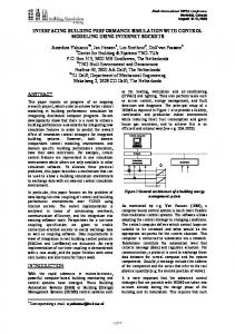
Today, buildings are one of the largest sectors of energy use (see Figure 1-1). In the United States, buildings account for 40 percent of national energy use; in the United Kingdom nearly 50 percent. In both countries, industrial energy use is now 30 percent or less of total energy use. In developed countries, buildings are also the single largest user of electricity, with buildings accounting for 72 percent of electricity use in the United States and 50 percent globally. Worldwide, total carbon dioxide emissions in 2005 were estimated at 28.051 billion metric tonnes: 40.6 percent from coal use (11.378), 39.1 percent from petroleum use (10.996), and 20.2 percent from natural gas use (5.666). Because buildings are the predominant users of electricity (coal, oil, and natural gas generation) and natural gas, they also are responsible for a large proportion of atmospheric pollution, including carbon dioxide, each year.
Recent studies in the United States have shown that improvements of 50–70 percent lower energy use beyond typical practice are easily attainable today at little or no increase in capital cost (Torcellini et al 2006). In fact, today it is cost-effective to build a net-zero energy building—one that annually produces more energy than it uses (Torcellini and Crawley 2006).
Many approaches are available for reducing the energy use in new and existing buildings. For example, building energy standards such as ASHRAE Standard 90.1-2004 (ASHRAE
1-4
100% 90% 80% 70% 60% 50% Commercial
40%
Residential Transportation
30%
Industrial 20% 10% 0%
Figure 1-1. Percentage Energy Use by Sector1 for the World and Selected Countries
2004a) provide guidance on cost-effective performance levels for individual components, systems, or whole buildings. Recently, ASHRAE (American Society of Heating, Refrigerating, and Air-Conditioning Engineers), the American Institute of Architects (AIA), the Illuminating Engineering Society of North American (IESNA), the U.S. Green Building Council (USGBC), and the U.S. Department of Energy (US DOE) have created a series of Advanced Energy Design Guides (AEDG) (ASHRAE 2004b, 2006, 2008a, 2008b) that provide recommendations for achieving 30 percent energy savings over the minimum code requirements of Standard 90.1. The AEDG provide simple look-up tables of minimum insulation for walls, roofs, and floors, minimum equipment performance, and maximum lighting power by climate zone. Building type experts created these recommendations from a series of alternate packages for reducing energy use. These packages were simulated to determine the best combination that met the 30 percent energy savings target.
1.5 Building Performance Simulation “Every building is a forecast. Every forecast is wrong.” (Brand 1994) 1
UK data from DTI (2002) and BERR (2008). Other data from EIA (2008).
1-5
Every building design is based on assumptions about how the building will be used, but from its opening day, a building will be used differently than its designers assumed or planned. Over time the intended use will change too. The building designed as a warehouse suddenly has a dropped ceiling and an air-conditioning system and is now an office; two years later kitchen equipment turns it into a restaurant.
Buildings entail complex heat and moisture interactions of a physical space and the occupants. Imagine a simple single room with an occupant; the room has four walls, a window in one wall, a floor, and a ceiling. The walls, floor, and ceiling all conduct heat because the temperature on the other side of each is different. If the air is moving, convection moves heat throughout the space. The outside environment—temperature, humidity, wind speed and direction, rain and other precipitation—is changing with weather patterns. The window transfers light and heat into or out of the room. Depending on the colour and reflectance of the surfaces, light is reflected throughout the room. The sun moves across the sky in an annual, seasonal, and diurnal pattern, which varies the direction and intensity of solar radiation. Moving clouds affect the amount of direct and indirect radiation that the window and the walls receive. Active systems for lighting, heating, cooling, ventilation, humidification, dehumidification as well as occupants and their equipment increase the complexity.
For designers to understand how energy is used in a space, they must model these complex interactions of heat, light, and moisture. Thus, tools to support the design of low-energy buildings must adequately represent these complex interactions. No longer are simple rules of thumb and peak load design calculations enough. Designers must have and use building performance simulation software to address the complexity of today’s buildings. Building simulation is key to evaluating critical building performance issues, such as human comfort and productivity, energy efficiency, code compliance, and carbon reduction.
Because no utility bills or other measured data exist to indicate how a new building will perform, simulation is the only means of predicting energy performance before that building is constructed and operated. Simulation also is the most effective way of estimating potential energy savings from retrofits in existing buildings. Energy and environmental performance simulation offers significant opportunities to support practitioners in reducing energy costs and subsequently preventing atmospheric pollution.
1-6
It is cheaper to simulate than to build a bad building.
Building performance simulation software has been available for more than 40 years (Clarke 2001), yet substantial recent advances in building simulation capabilities are providing new opportunities for integrating simulation into design practice. These advances range from fundamental improvements in simulation theory and models through software engineering, validation, user support, and systems that integrate multiple domains. During the past decade, building performance simulation programs have evolved from a strictly text-based, language-like input and output to multiple interfaces for different uses and users. Examples of robust building performance simulation programs include DOE-2.1E (Winkelmann et al 1993), EnergyPlus (US DOE 2008), ESP-r (ESRU 2008), and TRNSYS (Klein et al 2004). The robustness of the underlying simulation models and the user-friendliness of these programs have improved dramatically, gaining new users that might not have taken the time to learn the language of the underlying programs. At the same time, new users are demanding more—online help systems, tutorials, and support systems, such as predefined databases of climate, materials, constructions, systems, and exemplars.
Crawley et al (2005) compare the technical capabilities of EnergyPlus, ESP-r, TRNSYS and 17 other building performance simulation programs. This survey includes a brief overview of each program and a series of 14 tables comparing: general modeling features; zone loads; building envelope, daylighting, and solar; infiltration, ventilation, room air, and multizone airflow; renewable energy systems; electrical systems and equipment; HVAC systems; HVAC equipment; environmental emissions; climate data availability; economic evaluation; results reporting; validation; and user interface, links to other programs, and availability.
Building energy and environmental performance simulation programs have the capability to evaluate a wide range of response to external stimulus. Practitioners evaluating individual building design or retrofits often use these software tools. Other uses for building simulation programs include overheating prediction; heating and cooling equipment design, alternate technologies (energy efficiency and renewable energy) evaluation, regulatory compliance, or more recently, integrated performance views.
1-7
1.6 Simulation as a Tool for Building Policy Building performance simulation is regularly used to support decision making in the design or retrofit of individual buildings. Yet, the most powerful use lies beyond the performance of individual buildings in supporting building policy setting and decision making: to develop minimum standard regulations, assess the value of improved building performance for utilities or governments, or support high-level, public decision-making. Examples of policy targets include: •
defining a cost-effective performance level for various aspects of a new building energy efficiency standard,
•
evaluating the performance of an existing or proposed building energy standard,
•
establishing financial incentives for improved building energy performance, i.e., the value to the utility or political entity,
•
evaluating the potential impact of and direction for voluntary programs encouraging energy-efficient new building design or existing building retrofit,
•
evaluating the applicability of specific technologies or systems for the new building design or existing building retrofit markets,
•
evaluating the potential for introduction of renewable energy technologies at the building, community or regional level,
•
evaluating the potential impact of changes in regional, national or international policy,
•
evaluating requirements for existing or new energy supply at a regional or national level, and
•
evaluating the potential impact on building performance of changes relating to environment.
Coupling simulation with building models, which represent a range of building types and locations, can embody a portion of a building stock (existing or new, domestic, public, commercial, industrial, large, medium, or small) or the entire stock, which allows discrete modeling of building policy direction. Simulation provides policy decision makers a means of assessing what-if scenarios across a spectrum of buildings, ensuring that regulations and policy are set at the most financially and environmentally beneficial levels for individuals and the public.
The research documented here is not about the fundamental theory of building performance simulation or extending the capabilities of building simulation. Instead, a series of building
1-8
simulation studies demonstrates how building performance simulation informs and defines building energy policy. These studies include evaluating and setting performance levels for building energy standards, determining beyond-code utility incentives, and determining climatic influence and sensitivity on building operating performance. These four studies were selected to cover a range of policy targets where building simulation of large portions of a building sector is commonly used. Throughout the four studies, simulation is the key for evaluating the complex interactions of building thermo-physical characteristics, operation, and climate in support of the particular research goal or question. As a way to introduce building simulation as a policy tool, the examples of building simulation in use will demonstrate how they influenced decision makers crafting voluntary and mandatory programs for building energy efficiency and the policy analysis framework for using building simulation that is derived from these studies.
As Crawley et al (2005) showed, simulation tools can evaluate many aspects of building performance, such as capital and operating costs; energy performance and demand; human comfort, health and productivity; illumination; electrical flows; water and waste; acoustic design; renewable energy; and atmospheric emissions. Because the number of simulations involved was large, the research studies documented here focus on heating and cooling loads, energy use and cost, and capital cost.
THESIS: Building performance simulation is one of the most powerful tools available today for use by policy setters and decision makers looking to influence how buildings perform in terms of energy use and environmental impacts.
1.7 References —. 2008. Compact Oxford English Dictionary of Current English, 3rd ed. Oxford: Oxford University Press. http://www.askoxford.com/ —. 2008. American Heritage Dictionary of the English Language, 4th ed. New York: Houghton Mifflin Company. —. 2006. WordNet® 3.0. Princeton: Princeton University http://dictionary.reference.com/browse/modeling ASHRAE. 2004a. ANSI/ASHRAE/IESNA Standard 90.1-2004, “Energy Efficient Design of New Buildings Except Low-Rise Residential Buildings.” Atlanta: ASHRAE.
1-9
ASHRAE. 2004b. Advanced Energy Design Guide for Small Office Buildings. ASHRAE/ AIA/IESNA/USGBC/USGBC. Atlanta: ASHRAE. ASHRAE. 2006. Advanced Energy Design Guide for Small Retail Buildings. ASHRAE/ AIA/IESNA/USGBC/USGBC. Atlanta: ASHRAE. ASHRAE. 2008a. Advanced Energy Design Guide for K-12 School Buildings. ASHRAE/ AIA/IESNA/USGBC/USGBC. Atlanta: ASHRAE. ASHRAE. 2008b. Advanced Energy Design Guide for Small Warehouses and Self-Storage Buildings. ASHRAE/AIA/IESNA/USGBC/USGBC. Atlanta: ASHRAE. Brand, Steward. 1994. How Buildings Learn: What Happens after They’re Built. New York: Viking–Penguin Group. Clarke, J. A. 2001. Energy Simulation in Building Design, 2nd ed. Oxford: Butterworth and Heineman. Crawley, D. B., J. W. Hand, M. Kummert, and B. T. Griffith. 2005. Contrasting the Capabilities of Building Energy Performance Simulation Programs, July 2005. Washington: U. S. Department of Energy. Department of Trade and Industry. 2002. Energy Consumption in the United Kingdom. London: Department of Trade and Industry. Department for Business Enterprise & Regulatory Reform. 2008. Energy Consumption in the United Kingdom, 2008 Update. London: Department for Business Enterprise & Regulatory Reform. http://www.berr.gov.uk/whatwedo/energy/statistics/publications/ecuk/page17658.html Energy Information Administration. 2008. International Energy Outlook 2008. September 2008, DOE/EIA-0484 (2008). Washington: Energy Information Administration. http://www.eia.doe.gov/oiaf/ieo/ Energy Systems Research Unit. 2008. The ESP-r System for Building Energy Simulation, User Guide Version 11 Series, November 2008. Glasgow: University of Strathclyde. Howe, D. 2004. The Free On-line Dictionary of Computing http://dictionary.reference.com/browse/simulation . Klein., S. A., W. A. Beckman, J. W. Mitchell, J. A. Duffie, N. A. Duffie, T. L. Freeman, J. C. Mitchell, J. E. Braun, B. L. Evans, J. P. Kummer, R. E. Urban, A. Fiksel, J. W. Thornton, N. J. Blair, P. M. Williams, D. E. Bradley, T. P. McDowell, and M. Kummert. 2004. TRNSYS 16 – A TRaNsient System Simulation program, User Manual. Solar Energy Laboratory. Madison: University of Wisconsin-Madison. Mackintosh, C. R. 1925. Letter to Frances Newbery, 28 December 1925, Collection of the National Library of Scotland.
1-10
Scott, D. L. 2003. Wall Street Words: An A to Z Guide to Investment Terms for Today's Investor. New York: Houghton Mifflin Company. http://dictionary.reference.com/browse/simulation Torcellini, P. A., and D. B. Crawley. 2006. “Understanding Zero-Energy Buildings,” ASHRAE Journal, pp. 62-69, Vol. 48, No. 9 (September). Torcellini, P., S. Pless, M. Deru, B. Griffith, N. Long, and R. Judkoff. 2006. Lessons Learned from Case Studies of Six High-Performance Buildings, NREL TP-550-37542. Golden: National Renewable Energy Laboratory. US DOE. 2008. EnergyPlus. http://www.energyplus.gov Winkelmann, F.C., B.E. Birdsall, W.F. Buhl, K.L. Ellington, A.E. Erdem, J.J. Hirsch, and S. Gates. 1993. DOE 2 Supplement, Version 2.1E, LBL 34947, November 1993. National Technical Information Service, Springfield, Virginia.
1-11
Chapter 2 Building Performance Simulation in Policymaking We see the world piece by piece, as the sun, the moon, the animal, the tree; but the whole, of which these are the shining parts, is the soul. Ralph Waldo Emerson
2.1 Introduction In the context of building policy, performance simulation has been in wide use for more than 30 years in North America. These include evaluating the performance of new or proposed building energy standards, evaluating the value and design of energy savings programs for a utility or government entity, and evaluating the potential impact on the built environment of actions relating to climate change. Swan and Ugursal (2009) provide a comprehensive review of the various modeling techniques used for modeling residential sector energy consumption and they note:
“Two distinct approaches are identified: top-down and bottom-up. The top-down approach treats the residential sector as an energy sink and is not concerned with individual end-uses. It utilizes historic aggregate energy values and regresses the energy consumption of the housing stock as a function of top-level variables such as macroeconomic indicators (e.g. gross domestic product, unemployment, and inflation), energy price, and general climate. The bottom-up approach extrapolates the estimated energy consumption of a representative set of individual houses to regional and national levels, and consists of two distinct methodologies: the statistical method and the engineering method. Each technique relies on different levels of input information, different calculation or simulation techniques, and provides results with different applicability.”
Swan and Ugursal go further to say that the most appropriate use of these three approaches in modeling residential buildings corresponds to its strongest attribute: •
top-down approaches for supply analysis based on projections of energy demand,
2-1
•
bottom-up statistical techniques for determining energy end-uses including behaviour based on energy bills and simple surveys, and
•
bottom-up engineering techniques for explicitly calculating energy end-uses based on detailed characteristics, enabling impact of new (or alternative) technologies.
This chapter reviews related commercial building research in support of building policy where comparison of alternative technologies, systems, or climatic response is required—a bottom-up engineering approach—building energy standards, building stock models, utility incentives, and climate modeling. These areas are core to the discussion in subsequent chapters.
2.2 Evaluation of Building Energy Standards Building energy standards are a set of definitions of minimum performance of building components and equipment. They can be as simple as a table of minimum efficiency levels for a packaged air-conditioning unit, minimum insulation levels for walls and roofs, or maximum lighting power density. Building energy standards also can be performance based, requiring that a new or existing building has energy consumption no higher than a prescribed value. Where does building performance simulation fit into building energy standards? The primary aim of performance simulation in standards has been to evaluate the energy savings associated with a proposed standard (as compared to typical building practice or existing standards).
National building energy standards date back to the 1970s. For example, ASHRAE developed Standard 90-75 (ASHRAE 1975) to improve the efficiency of buildings in direct response to the oil embargo of the early 1970s. In the late 1970s, the US DOE proposed Building Energy Performance Standards (BEPS) (US DOE 1979) that set maximum energy performance levels for both residential and commercial buildings. A key feature of both the development and the proposed standards was the innovative use, at that time, of building performance simulation. Characteristics of typical buildings were collected throughout the United States, and baseline simulation models were constructed for more than 20 building types. Simulations were then performed and target levels established. Designers could then use building simulation models to demonstrate that their building performed at an energy level less than the maximum for that building type. Unfortunately, BEPS was too far ahead of the market and was buried under a landslide of adverse public comments.
2-2
Subsequent research by Pacific Northwest Laboratory (PNL 1983) used building simulation to propose aggressive updates to the then current Standard 90A-1980 in ASHRAE Special Project 41 (SP41) (Pacific Northwest Laboratory 1983). The SP41 proposals were based on life-cycle cost evaluation of the improved energy performance, evaluating ten buildings in six locations. This research was used as the starting point for the development of the next major update of Standard 90.1 in 1989 (ASHRAE 1989). Many of the public review drafts were tested by Pacific Northwest Laboratory for US DOE from 1985 through 1989, using five building prototypes and five locations (weather data) to evaluate energy savings levels. Interim energy simulation results were reported by Crawley and Briggs (1985a, 1985b), US DOE (1987), and Crawley and Boulin (1989), among others. A regional evaluation of state building energy codes in comparison with Standard 90.1-1989 was reported by Johnson et al (1988). The five building prototypes were developed to be typical of commercial buildings rather than representative of the entire stock of buildings. With only five building prototypes and five weather locations, the results from these studies could not extrapolated to represent the value of potential savings for the new standard across the entire commercial sector.
Carlo et al (2003) reported on an analysis of 12 prototype buildings to establish minimum requirements for a building energy-efficiency code in Brazil. While the code was based on Standard 90.1-1999, simulation allowed the researchers to customize the requirements to the climate and economic situation in Brazil. The goal was to create a multi-variable regression equation from the simulation results for calculating the annual energy consumption of a building in that location. The regression equation was tuned to that location with 10 coefficients. With 12 widely varying prototype buildings (in floor area and number of storeys), this required 1,616 combinations of envelope characteristics to be simulated. Carlo proposed to replicate this analysis for other Brazilian locations—requiring a similar number of simulations for each.
Recently, the European Union (EU) has established a Directive on the Energy Performance of Buildings (CEC 2001), which requires member states to create and deploy calculation methods for rating energy performance for buildings larger than 1,000 m2. This rating has a scale of A to H, where A is the lowest-energy and H the highest-energy buildings. Throughout Europe, this directive is requiring the use of building performance modeling of many more buildings than in the past. In the United Kingdom, the Netherlands, and a few other countries, the building performance modeling required to rate non-domestic buildings has been implemented in a simple set of equations for predicting energy use, known as
2-3
Simplified Building Energy Model (SBEM) (BRE 2008a, 2008b). Rather than a model of energy use of a specific building, the SBEM is a comparative model for rating the relative carbon emissions of the proposed building. The SBEM uses monthly utilization factor calculations and is limited in the technologies that it can evaluate.
2.3 Building Models, Building Stock, and Utility Incentives In a policy framework relating to building energy performance, the targets are individual buildings, but there is a need to establish how the proposed policy or standard will perform in a broader context—of new or existing buildings within a region or country. This requires an understanding of the building stock: •
the number and size of buildings being built and their operating and thermo-physical characteristics;
•
the number and size of existing buildings and their operation schedules, energy consumption, energy costs, and thermo-physical characteristics.
Internationally, detailed data relating new or existing commercial building stocks to actual building energy performance are relatively scarce in comparison to what Swan and Ugursal found for the residential sector. Macmillan and Köhler (2004) found that national residential and commercial sector-level energy use data were generally available throughout the world. But they also found that detailed data on the building stock and its energy use was very limited—citing studies in North America and Europe. Barrett (2009) supports this in a review of recent building stock research—saying that papers “concentrate on domestic buildings in detail with less about the non-domestic buildings.” Barrett goes on to say that the non-domestic sector accounts for a large and growing proportion of energy use (as evidence in Figure 1-1) but the literature he reviewed provides few details of this growth. He asserts that this is due to the more heterogeneous nature of the commercial building stock and that empirical data is sparse.
In the United States, the Energy Information Administration has conducted quadrennial energy consumption surveys since 1979 for commercial, industrial, and residential buildings. These surveys provide a wealth of information about the numbers and consumption of the entire building stock based on a statistical representation of the sector and the representativeness of several thousand buildings for each sector. The Commercial Building Energy Consumption Survey (CBECS) comprises survey data on more than 4,000 U.S. buildings (EIA 2007, 2002). But these data are not complete thermo-physical models of
2-4
each building. For example, there is little detail on the energy consuming systems or the thermal characteristics of the building envelope. Further, EIA masks certain data such as number of workers, number of floors and floor area in large buildings (more than 20 storeys and/or 45,000 m2) so that individual buildings cannot be identified. Griffith et al (2008) discusses the limitations of using the survey data in the context of a bottom-up research study—requiring supplementing the data with assumptions, defaults, data from other literature and probabilistic assignments.
Recently, Natural Resources Canada has published a similar commercial building survey for Canada (NRCan 2006), the Commercial and Institutional Consumption of Energy Survey (CICES). CICES includes information on 7,349 buildings, but it focuses on the floor area, building type, and the forms and amounts of energy used in the survey year. Key information such as the number of floors or any information about the building envelope or heating and cooling systems is not collected. This limits the use of the CICES as a source of input for building simulation.
California has created a similar survey with more details on the surveyed buildings (PG&E 1999). This survey was recently updated and extended state-wide as reported by Kinney and Piette (2002). The updated survey included the collection of sufficient building characteristics so that calibrated simulation models of each of the more than 2,800 commercial buildings could be created (Ramirez et al 2005).
The Building Owners and Managers Association (BOMA) publishes an annual report on U.S. office markets (BOMA 2007). BOMA publishes information obtained from more than 3,000 office buildings including income, expenses, energy consumption, rent, and occupancy rate. But similar to the surveys noted above, the minimum geometric and other key information required for simulating the performance of those buildings is not collected by BOMA.
In Scotland, the Energy Systems Research Unit (ESRU) Domestic Energy Model (EDEM) (Clarke et al 2003, Clarke et al 2008, ESRU 2008) supports energy policy formulation for the residential sector. It provides representations of the entire domestic sector for Scotland, which allows policy makers to quickly apply a wide range of improvements analytically and evaluate which will provide the best energy performance or reduction in carbon. Analyses performed include national housing stock fabric upgrade strategies, local community
2-5
upgrade strategy and carbon roadmap formulation, carbon and energy performance, and energy labelling in compliance with the EU Energy Performance of Buildings Directive. But the EDEM is limited to the domestic sector. An equivalent model for the non-domestic sector is not available.
The International Energy Agency (IEA) also publishes energy use data for buildings in member countries (IEA 2008), but this is a statistically disaggregated estimate, a top-down inference based on energy production and supply data. Little information is available on the average energy performance of buildings by type or climate zone.
While survey data are extremely useful for a building stock snapshot, they usually are limited by the information collected. Only rarely are there enough data to create a building model in energy simulation software. Several projects have worked to use existing survey data to create prototypes that represent large portions or building types and regions. Briggs et al (1987, 1992) created 20 existing office building prototypes, and Crawley and Schliesing (1992) created 10 new office building prototypes for use by the Gas Research Institute in research and market assessment. The existing building models were based on the 1979 Nonresidential Buildings Energy Consumption Survey (NBECS), the first survey in the CBECS. The new building models were based on Standard 90.1. In both cases, substantially more input data were required for the models, and sources are documented in their reports. Huang et al (1991) extended the prototypes to the entire commercial sector for 20 urban markets in the United States. Huang and Franconi (1999) updated the prototypes to evaluate the contributing components of commercial building loads. In all cases, these prototypes were limited by the assumptions that the authors had to make to create complete simulation models. Often these assumptions were not well documented.
Rather than producing prototypes to represent multiple buildings, Griffith et al (2007, 2008) created building simulation models for each of the more than 4,000 buildings in the 2003 CBECS. These building models were developed first as a baseline with energy features and performance consistent with Standard 90.1-2004 (ASHRAE 2004). Then low-energy technologies and renewable energy systems anticipated to be available by 2025 were applied to the models. The result was an assessment of the technical potential for achieving zeroenergy buildings throughout the commercial building sector in the United States. The conclusion was that the zero-energy building goal could be, on average, achieved in the commercial building sector. Building types which can reach the zero-energy target easily:
2-6
offices, warehouses, schools, and retail. Restaurants, hospitals, and other energy-intensive building types will be the hardest to bring to net zero-energy. While not creating prototypes improved the breadth and representativeness of the analysis, it also created a logistic and quality assurance issue—how to deal with multiple thousands of building models. Griffith used an XML schema associated with a database of inputs to define each model. Since the inputs were derived directly from the CBECS data or related assumptions, the inputs could be automatically verified before a series of simulations were started.
Recently, Deru et al (2008) published a set of 16 benchmarks for new commercial buildings based on the 2003 CBECS and ASHRAE Standard 90.1-2004. The benchmark buildings descriptions include a scorecard comprising detailed documentation of all inputs and assumptions as well as information and data sources. Each benchmark building also has a corresponding EnergyPlus input files (US DOE 2007).
For utilities, the economic benefit of incentives paid for improved energy efficiency is often obscured by their regulated environment and the complex valuation of equitable sharing of net benefits, cost capitalization, and risks with their stakeholders. Rather than evaluating individual incentives, they aggregate the energy efficiency measures into a portfolio, essentially a top-down approach to the utility sector. For example, Cappers et al (2009) present an analysis of energy efficiency incentives in the context of a prototypical investorowned utility. This analysis adapts a spreadsheet-based financial model (known as the Benefits Calculator) developed in support of the National Action Plan for Energy Efficiency (Jensen 2007).
The literature is full of similar portfolio-centric approaches to energy efficiency with a focus on program costs, costs and benefits to ratepayers, and similar utility rate case calculations. Many consultants offer services to develop and evaluate incentives for utilities but few publish in the peer-reviewed literature, which may indicate that they see their utility incentive calculation methodologies and procedures as a business advantage. Instead, utilities focus on supporting their customers and administering the incentive programs. TerMartirosyan (2003) says that this is due to changes which began in the late 1980s, with public utility commissions and other regulators focusing on regulation of the incentives themselves rather than the rate of return the utility could earn. For utilities, this has a twofold result—decreased quality and cuts in service (as described by Ter-Martirosyan) and less
2-7
interest in detailed engineering approaches that are overwhelmed by their heavily regulated environment.
2.4 Climate Data in Building Performance Modeling For many years, the unavailability of data was a limiting factor in what could be done to represent climatic conditions in a specific location or common climate conditions in a zone. More recently, better data sets have allowed aggregation of multiple locations and statistics to create maps and climate zones.
As recently as 15 years ago, limited weather data were available to building simulation users. Even in the early 1990s, the number of weather files available in the United States was fewer than 100 locations for a country of nearly 10 million km2. Today, the United States has more than 1,000 “typical” weather files available in the TMY3 format (Wilcox and Marion 2008) and another 1,000 weather files are available internationally1. Until more typical weather files become available as more meteorological data are collected, tools such as Meteonorm2 allow knowledgeable users to interpolate and extrapolate weather data for use in simulation tools, but even these tools are limited by the available data and statistics.
Building standards have used a variety of climate zones over the years. In Standard 90.11989, 38 climate regions were defined to represent that range of climatic conditions worldwide. A subsequent revision to the climate zones in Standard 90.1-1999 took the number of climate zones to 73. When this number proved unwieldy, research by Briggs et al (2003a, 2003b) evolved eight major climate zones with subcategories of wet and dry. This resulted in 15 climate zones, as shown in Standard 169-2006 (ASHRAE 2006).
Crawley et al (1999) proposed a new, neutral weather data format for building performance simulation programs. In the past nine years, more than 20 simulation tools and providers of weather data have adopted this format or adapted their climate data tools to read or write it. Hensen (1999) reviewed and identified issues with availability, temporal resolution, and data required for building performance simulation. He found that climatic data availability and
1
A list of publicly available typical meteorological data for more than 2,100 locations from 20 data sets including source is available: http://energyplus.gov/weatherdata_sources.cfm. This list omits proprietary or older data sets, such as the Test Reference Year (TRY) developed in the EU (CEC 1985), the older TRY in the United States (NCDC 1976), and the Weather Year for Energy Calculations (WYEC) and WYEC2 data sets from ASHRAE (1985, 1997). 2 http://www.meteotest.ch
2-8
resolution was still a significant issue in building performance simulation and that building performance tools increasingly need additional data such as illuminance, sky temperature, and pollutants that have traditionally not been widely available.
2.5 Modeling Climate Change and Urban Heat Islands During the past 15 years, much scientific work has been published on humans’ potential impact on climates. For their Third Assessment Report in 2001 (IPCC 2001), the United Nations Intergovernmental Panel on Climate Change (IPCC) developed a set of economic development scenarios, which were then run with the four major general circulation models (GCM) to estimate the anthropogenesis-forced climate change. These GCMs produce worldwide grids of predicted monthly temperature, cloud, and precipitation deviations from the period of 1961–1990. As this period is the same used for several major typical meteorological year data sets, these typical data sets can be used as a starting point for modifying weather files to represent predicted climate change. The IPCC summarizes the impact on the built environment simply as “increased electric cooling demand and reduced energy supply reliability.”
Trigo and Palutikof (1999) reanalyzed the HadCM2 data for Portugal using artificial neural networks to downscale the data to predict future climate conditions in Portugal. They found that the HadCM2 produced unreliable results for local sites in Portugal.
In a proof of concept study, Crawley (2003) found that temperature increases expected from climate change would substantially increase the operating time for cooling equipment in the United States and would shift many locations from heating (typically fossil fuel-based systems with conversion efficiencies of less than 1) to cooling (predominantly electrical systems with COPs greater than 2). By adding the annual average temperature predicted by the IPCC climate change scenarios to existing weather data for a few U. S. locations, he showed that annual average space temperatures would increase toward the cooling temperature set-point (see Figure 2-1).
Hacker et al (2005) looked at the potential summer overheating risks associated with the climate change scenarios in the United Kingdom for offices, schools, and houses. They then proposed measures for mitigating the overheating risks. Levermore took this research further
2-9
25
Outdoor Dry Bulb [C] First Floor Mean Air Temperature First Floor Mean Radiant Temperature Second Floor Mean Air Temperature Second Floor Mean Radiant Temperature
20
Temperature, C
15
10
5
0 1990
2040
2070
2100
Figure 2-1. Annual Average Outdoor Temperature and Predicted Indoor Mean Air and Radiant Temperature, °C, by Zone in Chicago, Illinois, USA (Crawley 2003) and created climate change weather data for Edinburgh, Manchester, and London (CIBSE 2004)—tabular design conditions for potential future conditions. This results in a static data set of future climate conditions based on one model.
To support the development of the 2007 update report for the IPCC, Scott et al (2007) evaluated the potential impacts of climate change using a sector-wide, top-down model of the building sector, estimating increases in energy use and the value of building energyefficiency programs. In their work, they started with an overview of the building sector in terms of energy use and estimated the impacts of changes in climate. Rong et al (2007) and Edmonds et al (2007) document a global macroeconomic model of energy use which includes the building sector by representing the demand for energy services—heating, cooling, and lighting and future scenarios of efficiency, growth in use, and climate change. While this might be useful to estimate the impacts on a sector, it does not provide insights into which building systems are the largest contributors to the changes in energy performance. That information is only available from a bottom-up model of the sector with explicit building models and thermo-physical characteristics.
Studies of urban heat island (UHI) or urbanization conducted during the past 50 years have provided detailed measurements of the diurnal and seasonal patterns and differences between
2-10
urban and rural climatic conditions. The U.S. Environmental Protection Agency (US EPA) estimates that an annual mean air temperature of the urban center of a city with 1 million people or more can be 1–3°C warmer than its surroundings (US EPA 2008). Wypych and Bokwa (2006) state:
“In many cities, the air temperature is, on average, 0.5 to 0.8°C higher than the surrounding non-urban areas. In winter, the average temperature difference is even greater, between 1.1 and 1.6°C.”
They further state:
“The number of inhabitants is a major factor controlling the development of the UHI. In cities with populations between 500,000 and 1,000,000 people, air temperatures are usually 1.1 to 1.2°C higher than surrounding non-urban areas. For cities with more than a million people, the difference between urban and non-urban average temperatures increases to between 1.2 and 1.5°C.”
They go further to say that “maximum observed differences can be much higher” and cite 10°C for a city with a population of 10 million. While heat islands have been shown to be a function of both population and microclimatic and site conditions, they can be generalized into predictable diurnal and seasonal patterns.
Matsuura (1995) studied the impacts on the performance of two buildings by altering the air temperature in weather data by 1°F and taking into account the shading effects of a nearby building. He found that a significant decrease in energy loads occurred in both cold climates (Duluth, Minnesota) and hot climates (Phoenix, Arizona). Carlo and Lamberts (2001) studied the impact of urbanization on two prototype office buildings using DOE-2.1E. Temperature data from local airports were adjusted to account for microclimatic effects. Solar radiation data were not available and were calculated. Carlo and Lamberts found that microclimatic variation within an urban area can be as great an influence on building performance as building characteristics and configuration. Akbari and Konopacki (2005) evaluated the potential energy savings from mitigating heat island effects. They used a constant change in temperature applied in building simulation models. This constant change in temperature does not take into account the variation in diurnal demonstrated by Oke (1988).
2-11
While the scientific literature is full of studies looking at the impact of climate change driven by human activity, there is little research on the impact of climate change or urban heat islands on building operation and performance across the world.
2.6 Data Issues in MultiBuilding Studies The largest challenge of research involving large numbers of simulation models is dealing with the immense amount of data that building performance simulation programs can create. For example, a single EnergyPlus simulation with 10-minute time step output can produce more than 600 megabytes of data. Handling the data from hundreds or thousands of simulations can overwhelm a researcher.
In their studies of Standard 90.1 in the 1980s, Crawley et al (1985a, 1985b, 1989) created five building type DOE-2.1E models for the commercial sector. They were based on the earlier models created for SP 41 and included variants tied to five climate regions throughout the United States. Three variations on the base model were created—Standard 90-75, Standard 90A-1980 (ASHRAE 1980), and the proposed draft standards, which became Standard 90.1-1989. This large number of simulations (5 buildings x 5 climates x 3 standards) required that the structure of the analysis be carefully designed, including a systematic file-name convention that included abbreviations for building type, climate zone, and variant of the standard. The researchers also created batch scripts to automate running the simulations and extracting summary energy results. When the ASHRAE committee developing the standard created three drafts in three years, this structure and automation proved invaluable. When Johnson et al (1988) studied the potential for upgrading building energy standards in the Pacific Northwest, they were able to quickly adapt the 90.1 scripts and input files and complete the analysis in less than two months.
In the study for the Gas Research Institute described above, Briggs et al (1992) chose to create a spreadsheet that included the key characteristics definitions for the building prototypes and all the parts of the simulation input files. Invoking a macro in the spreadsheet automatically generated the input files for the existing office building prototypes. This provided the added advantage of having all the input in tabular form, ready for insertion into the research report. A further advantage was that the prototypes could be modified easily and the data checked carefully.
2-12
When Huang and Franconi (1999) created new prototypes, they constructed these as snippets of simulation input files. The user simply invoked a batch script that assembled the correct parts into a complete input file.
Griffith et al (2007, 2008) took a more robust approach in studying the technical potential for achieving zero-energy commercial buildings. Because this study involved creating a building simulation model for each of the more than 5,000 buildings in the 2003 CBECS, it necessitated the development of a method for automatically creating the input files. Griffith created a set of high-level XML definitions for all the key inputs, such as floor area, weather data, floor-to-floor height, lighting power intensity, and HVAC system. He created a specific part of the input file for each of these XML definitions. When the XML scripting tool was passed an XML key, a specific input file could be created. Further scripting tools were created to automatically submit simulations on multi-core computer clusters and extract summary results from the completed simulations.
Creating a structured approach to studies involving multi-building simulations is also vital to quality assurance. Checking the values of individual inputs is not easily accomplished if several hundred or thousand individual input files are involved. Summary tables of the values of key inputs that can be checked easily and then automatically transferred to input files are critical.
Donn (2007) studied the role of Quality Assurance (QA) in environment design decision support tools for architecture, including a variety of building performance simulation tools for daylighting, thermal design, and acoustics. He found that not only was it critical to have QA procedures as a standard part of any building analysis, it was critical to have QA measures that are codified and incorporated into the simulation tools themselves. These QA measures would be reality tests to examine whether outcomes from the design decision tools behave in a believable manner— like a real building. Donn also proposed the establishment of a shared database on QA performance data available to all design decision tool users.
2.7 Summary This chapter has presented a review of the literature relating to commercial building policy studies in a number of areas: •
development and evaluation of building energy standards
•
buildings models and building stock
2-13
•
utility incentives
•
climate data for building performance modeling
•
modeling climate change and urban heat islands
•
QA and data volume issues in multi-building studies
For the development and evaluation of building energy standards, the literature showed that having a number of prototype buildings which could represent the wider building stock was important. Several of the studies (US DOE 1987, Johnson et al 1988) had few buildings and the results could not be extrapolated to the wider commercial building sector. Similarly, a large number of buildings raised the level of complexity as seen in the work by Carlo et al (2003) which has implications for data management and QA. On the other extreme, a simple model such as the SBEM can inhibit the adoption of new technologies. It is important to be able to adequately cover the range of characteristics expected for the buildings to be simulated.
In setting policy for commercial buildings, the ultimate targets are individual buildings. But how the proposed policy will perform in a broader context of a region or country or a building type or entire building sector is important as well. Policy makers need to be able to relate individual decisions to their impacts. In that context, this requires an understanding of the target building stock including the size and number of buildings as well as their operating and physical characteristics. The literature review of building stock found few sources of detailed data below sector-level energy use. A few building characteristics surveys were available in North America and Europe but they all had limitations in the depth or quality of data available for building modelling. The exception was in California where the commercial building survey was coupled with calibrated building simulation models. Further review found work that filled in the data missing from the surveys with assumptions, rules of thumb, and other data. Often these supplementary data were not described in the reports or other documentation, making it difficult for potential users to fully understand the models. More recent benchmark buildings (Deru et al 2008) are working to overcome these limitations by fully documenting all input assumptions and sources of data in the building models.
Interestingly, there were very few published studies on setting the level and technical attributes for utility incentives in the peer-reviewed literature. Most utility incentives literature focused instead on the delivery and administration of incentive programs for energy efficiency in commercial buildings.
2-14
Several studies noted that despite a substantial increase in the number of locations for which climate data are available over the last few years, limited availability and temporal resolution in many areas throughout the world is still an important issue.
In investigating studies relating to modeling climate change and urban heat islands, it was found that most were limited in scope to a small region or were top-down estimates of impacts. In addition, the methods used to create climate data to represent climate change or urban heat islands were usually limited to simply adding the same temperature change to every hour. This does not agree with the findings of the IPCC, Oke, and others that diurnal temperature patterns change along with the average change in temperature. The global circulation models used in the study of climate and the studies where urban heat island is documented show a clear compression of the diurnal temperature range is part of the change in average temperature.
Finally, studies that dealt with large number of building simulations found a number of means of automating the creation of building models. Some used spreadsheets, others scripts, but in all cases, it was critical to having a structured approach for the validation and error checking of individual inputs. This structure forms a critical part of the framework necessary for building research support policy-makers.
2.8 References Akbari, H., S. Konopacki. 2005. “Calculating Energy-Saving Potentials of Heat-Island Reduction Strategies,” LBNL-47307. Berkeley: Lawrence Berkeley National Laboratory. ASHRAE. 1975. ASHRAE/IES Standard 90-75, “Energy Conservation in New Building Design.” ASHRAE: New York. ASHRAE. 1980. ANSI/ASHRAE/IES Standard 90A-1980, “Energy Efficiency Design of New Buildings.” ASHRAE: Atlanta. ASHRAE. 1985. Weather Year for Energy Calculations. American Society of Heating, Refrigerating, and Air-Conditioning Engineers, Atlanta, Georgia. ASHRAE. 1989. ANSI/ASHRAE/IES Standard 90.1-1989, “Energy Efficient Design of New Buildings Except Low-Rise Residential Buildings.” ASHRAE: Atlanta. ASHRAE. 1997. WYEC2 Weather Year for Energy Calculations 2, Toolkit and Data. Atlanta: ASHRAE.
2-15
ASHRAE. 2004. ANSI/ASHRAE/IESNA Standard 90.1-2004, “Energy Efficient Design of New Buildings Except Low-Rise Residential Buildings.” Atlanta: ASHRAE. ASHRAE. 2006. ANSI/ASHRAE Standard 169-2006, “Weather Data for Building Design Standards.” Atlanta: ASHRAE. Barrett, M. 2009. “Policy Challenges for Building Stocks,” in Building Research and Information, March/April 2009, 32 (2): 201-205. Building Owners and Managers Association International. 2007. 2007 Experience Exchange Report. BOMA, Washington, D.C. Briggs, R. S., D. B. Crawley, and D. B. Belzer. 1987. Analyses and Categorization of the Office Building Stock, GRI-87/0244, October 1987. Chicago: Gas Research Institute. Briggs, R. S., D. B. Crawley, and J. S. Schliesing. 1992. Energy Requirements for Office Buildings, Volume 1, Existing Buildings, GRI-90/0236.1, February 1992. Chicago: Gas Research Institute. Briggs, R. S., R. G. Lucas, and Z. T. Taylor. 2003a. “Climate Classification for Building Energy Codes and Standards: Part 1—Development Process,” 4610. January 2003. ASHRAE Transactions 2003, V. 109, Pt. 1. Briggs, R. S., R. G. Lucas, and Z. Todd Taylor. 2003b. “Climate Classification for Building Energy Codes and Standards: Part 2—Zone Definitions, Maps, and Comparisons,” 4611. January 2003. ASHRAE Transactions 2003, V. 109, Pt. 1. British Research Establishment. 2008a. “National Calculation Method.” http://www.ncm.bre.co.uk/ British Research Establishment. 2008b. “Simplifed Building Energy Model Technical Manual.” Garston: British Research Establishment. Cappers, P., C. Goldman, M. Chait, G. Edgar, J. Schlegel, and W. Shirley. 2009. Financial Analysis of Incentive Mechanisms to Promote Energy Efficiency: Case Study of a Prototypical Southwest Utility. Berkeley: Lawrence Berkeley National Laboratory. Carlo, J., and R. Lamberts. 2001. “Urban Climate and its Influence on Energy Consumption: A Case Study in Two Brazilian Cities,” in Proceedings of Building Simulation 2001, pp. 167-1174, Rio de Janiero, Brazil, August 2001. IBPSA. Carlo, J., E. Ghisi, and R. Lamberts. 2003. “The use of Computer Simulation to Establish Energy Efficiency Parameters for a Building Code of a City in Brazil,” in Proceedings of Building Simulation 2003, pp.131-138, Eindhoven, Netherlands, August 2003. IBPSA. Chartered Insitute of Building Services Engineers. 2004. Weather Data with Climate Change Scenarios, CIBSE TM34. London: CIBSE.
2-16
Clarke, J. A., C. M. Johnstone, M. Lever, L. B. McElroy, F. McKenzie, G. Peart, L. Prazeres, and P. A. Strachan. 2003. “Simulation Support for the Formulation of Domestic Sector Upgrading Strategies,” in Proceeedings of Building Simulation 2003, pp. 219-226, Eindhoven, Netherlands, August 2003. IBPSA. Clarke, J. A., S. Ghauri, C. M. Johnstone, J. M. Kim, and P. G. Tuohy. 2008. “The EDEM Methodology for Housing Upgrade Analysis, Carbon and Energy Labelling and National Policy Development,” in Proceedings of the eSim 2008 Conference, pp. 135-142. Quebec City, Canada. IBPSA Canada. Commision of the European Communities. 1985. Test Reference Years, Weather data sets for computer simulations of solar energy systems and energy consumption in buildings, CEC, DG XII. Brussels, Belgium: Commission of the European Communities. Commission of the European Communities. 2001. Directive on the Energy Peformance of Buildings, Brussels, Belgium. Crawley, D. B., and R. S. Briggs. 1985a. “Standard 90: The Value.” ASHRAE Journal, pp. 18-23, Vol. 27, No. 11 (November). Crawley, D. B., R. S. Briggs. 1985b. “Envelope Impacts of ASHRAE Standard 90.1P: A Case Study View,” in Proceedings, Thermal Performance of the Exterior Envelopes of Buildings III, pp. 1128-1140. ASHRAE/DOE/BTECC, Clearwater Beach, Florida, 2-5 December 1985. Atlanta: ASHRAE. Crawley, D. B., and J. J. Boulin. 1989. “Standard 90.1's ENVSTD: Both a Compliance Program and an Envelope Design Tool,” in Proceedings, Thermal Performance of the Exterior Envelopes of Buildings IV, pp. 332-333. ASHRAE/DOE/BTECC/CIBSE, Orlando, Florida, 4-7 December 1989. Atlanta: ASHRAE. Crawley, D. B., and J. S. Schliesing. 1992. Energy Requirements for Office Buildings, Volume 2, Recent and Future Buildings, GRI-90/0236.2, March 1992. Chicago: Gas Research Institute. Crawley, D. B., J. W. Hand, and L. K. Lawrie. 1999. “Improving the Weather Information Available to Simulation Programs,” in Proceedings of Building Simulation ’99, Volume II, pp. 529-536. Kyoto, Japan, September 1999. IBPSA. Crawley, D. B. 2003. “Impact of Climate Change on Buildings,” in Proceedings of the CIBSE/ASHRAE International Conference 2003. September 2003, Edinburgh, Scotland. London: CIBSE. Deru, M., D. Crawley, B. Lui, and J. Huang. 2008. Commercial Building Benchmarks. Washington: US DOE.
2-17
Donn, M. R. 2007. Simulation of Imagined Realities: Environmental Design Decision Support Tools in Architecture, PhD thesis, School of Architecture. Wellington: Victoria University of Wellington. Edmonds, J. A., M. A. Wise, J. J. Dooley, S. H. Kim, S. J. Smith, P. J. Runci, L. E. Clarke, E. L. Malone, and G. M. Stokes. 2007. Global Energy Technology Strategy: Addressing Climate Change. College Park, Maryland: Joint Global Change Research Institute. Energy Information Administration. 2002. Commercial Buildings Energy Consumption Survey—Commercial Buildings Characteristics 1999. Washington: Energy Information Administration, US Department of Energy. Energy Information Administration. 2007. Commercial Buildings Energy Consumption Survey—Consumption and Expenditures 2003. Washington: Energy Information Administration, US Department of Energy. http://www.eia.doe.gov/emeu/cbecs/cbecs2003/ Energy Systems Research Unit. 2008. ESRU Domestic Energy Model. Glasgow: Energy Systems Research Unit, University of Strathclyde. http://www.esru.strath.ac.uk/Programs/EEff/index.htm Griffith, B., N. Long, P. Torcellini, R. Judkoff, D. Crawley, and J. Ryan. 2007. Assessment of the Technical Potential for Achieving Net Zero-Energy Buildings in the Commercial Sector, NREL/TP-550-41957, December 2007. Golden: National Renewable Energy Laboratory. Griffith, B., N. Long, P. Torcellini, R. Judkoff, D. Crawley, and J. Ryan. 2008. Methodology for Modeling Building Energy Performance Across the Commercial Sector, NREL/TP550-41956, March 2008. Golden: National Renewable Energy Laboratory. Hacker, J., M. Holmes, S. Belcher, and G. Davies. 2005. Climate Change and the Indoor Environment: Impacts and Adapation, TM36:2005. London: CIBSE. Hensen, J. 1999. “Simulation of Building Energy and Indoor Environmental Quality—Some Weather Data Issues,” in Proceedings of the International Workshop on Climate Data and Their Applications in Engineering, 4-6 October. Prague: Czech Hydrometeorological Institute. Huang, Y.J., H. Akbari, L. Rainer, and R. Ritschard. 1991. 481 Prototypical Commercial Buildings for Twenty Urban Market Areas, GRI-90/0326. Chicago IL: Gas Research Institute. Huang, Y. J., and E. M. Franconi. 1999. Commercial Heating and Cooling Loads Component Analysis, LBNL-37208. Berkeley, CA: Lawrence Berkeley National Laboratory.
2-18
Intergovernmental Panel on Climate Change. 2001. Climate Change 2001: Impacts, Adaptation and Vulnerability. Cambridge: Cambridge University Press. Intergovernmental Panel on Climate Change. 2007. Climate Change 2007: Synthesis Report. Cambridge: Cambridge University Press. International Energy Agency. 2008. Key World Energy Statistics 2008. Paris: International Energy Agency. Jensen, V. 2007. Aligning Utility Incentives with Investment in Energy Efficiency: A Product of the National Action Plan for Energy Efficiency. Fairfax, Virginia: ICF International, Inc. Johnson, B. K., D. B. Crawley, and R. C. Perez. 1988. “Comparison of Energy Conservation Standards for New Commercial Buildings in the Pacific Northwest,” in Proceedings, Pacific Northwest Regional Economic Conference, Boise, Idaho, 30 April 1988. Kinney, S., and M. A. Piette. 2002 Development of a California Commercial Building Energy Benchmarking Database, May 2002, LBNL-50676. Berkeley: Lawrence Berkeley National Laboratory. Macmillan S, and J. Kohler. 2004 Modelling Energy Use in the Global Building Stock: a Pilot Survey to Identify Available Data Sources. Norwich: Tyndall Centre for Climate Change Research. Technical Report 6. Matsuura, K. 1995. “Effects of Climate Change on Building Energy Consumption in Cities,” in Theoretical and Applied Climatology, Volume 51, Numbers 1-2, March 1995, pp. 105-117. National Climatic Data Center. 1976. Test Reference Year (TRY), Tape Reference Manual, TD-9706, September 1976. Asheville, North Carolina: National Climatic Data Center, U.S. Department of Commerce. Natural Resources Canada. 2006. 2004 Commercial and Institution Consumption of Energy Survey. Ottawa, Ontario, Canada: Natural Resources Canada. Oke, T. R. 1988. Boundary Layer Climates. Routledge, New York. Pacific Gas and Electric Company. 1999. Commercial Building Survey Report. San Francisco. Pacific Northwest Laboratory. 1983. Recommendations for Energy Conservation Standards and Guidelines for New Commercial Buildings. PNL-4870. October 1983. Pacific Northwest Laboratory, Richland, Washington. Ramirez, R., F. Sebold F, T. Mayer, M. Ciminelli, and M. Abrishami. 2005. “A Building Simulation Palooza: the California CEUS Project and DrCEUS,” in Proceedings of Building Simulation 2005, pp. 1003-1010, Montreal, Canada, August 2005. IBPSA.
2-19
Rong, F., L. Clarke, and S. Smith. 2007. Climate Change and the Long-Term Evolution of the U.S. Buildings Sector, PNNL-SA-48620. Richland: Pacific Northwest National Laboratory. Scott, M. J., J. A. Dirks, and K.A. Cort. 2007 “The Value of Energy Efficiency Programs for U.S. Residential and Commercial Buildings in a Warmer World,” Mitigation and Adaptation Strategies for Global Change 13 (4): 307-339. Swan, L. G., V. I. Ugursal. 2009. “Modeling of End-use Energy Consumption in the Residential Sector: A Review of Modeling Techniques,” Renewable and Sustainable Energy Reviews, in press. Ter-Martirosyan, A. 2003. The Effects of Incentive Regulation on Quality of Service in Electricity Markets, working paper. Washington: George Washington University. Trigo, R. M. and Palutikof, J. P. 1999 “Simulation of Daily Temperatures for Climate Change Scenarios over Portugal: a Neural Network Approach, ” Climate Research 13: (45–59). US DOE. 1979. Notice of Proposed Rulemaking for Building Energy Performance Standards. Washington, D.C.: USDOE. US DOE. 1987. Notice of Proposed Rulemaking, Interim Standard, Voluntary Performance Standards for New Commercial and Multi-Family High Rise Residential Buildings. Washington, D.C.: USDOE. US DOE. 2007. EnergyPlus Version 2.0. http://www.energyplus.gov/. US EPA. 2008. Reducing Urban Heat Islands: Compendium of Strategies. Washington, D.C.: US EPA. http://www.epa.gov/heatisland/resources/compendium.htm Wilcox, S., and W. Marion. 2008. User’s Manual for TMY3 Data Sets, NREL/TP-58143156, April 2008. Golden, Colorado: National Renewable Energy Laboratory. Wypych, S., and A. Bokwa. 2006. “Urban Heat Island.” http://www.atmosphere.mpg.de/enid/f09325074bbaae311f19bbbf4a5e3f0c,0/2__Urban_ Climate/-_Heat_Island_3rl.html
2-20
Chapter 3 Defining Models and Processes to Support Policy Analysis When you can measure what you are speaking about, and express it in numbers, you know something about it, but when you cannot measure it, when you cannot express it in numbers, your knowledge is of a meager and unsatisfactory kind. Lord William Thomson Kelvin
3.1 Introduction A key part of simulating a building is creating a model to represent that building. In the more traditional use of building simulation as described in Chapter 1, a single building may be modeled in detail for response to one or more conditions. But when using building simulation in policy analysis to establish new building standards or looking at impacts of wide changes to the building sector, the interest is not a single building but a segment or entire building stock of a region or country. Thus the analysis must establish not a single representation but a range of attributes, including building size, configuration, internal loading, scheduling, systems, and other key building characteristics. In addition, because these research studies often involve hundreds or thousands of files—input, output, and weather data—the analysis requires a structured approach for constructing inputs, managing the outputs, and deriving summary data. This chapter first describes the research approach for each of the studies, comparing the simulation programs, building models, climatic data, research questions (of each study) and the parameters that were tested. This chapter then describes the development of building models and processes for the multi-building policy analyses described later in this thesis. Section 1.6 listed examples of building policy targets including international, national or regional policy, developing and evaluating energy efficiency standards for buildings, establishing the structure and design of a voluntary energy efficiency program, and setting appropriate levels of financial incentives for utilities. Each of these policy-setting projects required a multi-building analytical structure to evaluate multiple building use types; ranges of building thermal characteristics; internal loads; schedules; climate regions; construction methods and costs; and lighting, heating, cooling, and ventilating systems. The following
3-1
four policy studies cover aspects of all the policy targets identified above. In addition, the structures created to manage the simulation processes are described for each of the studies. The first two studies were conducted from a Canadian view—developing building energy standards or setting utility incentives for Canadian locations. The third study describes analysis performed to support the development of a new voluntary energy efficiency program in the U. S. The fourth is an evaluation of local impacts of climate change and heat island on a small office building, including the influences of energy efficiency and renewable technologies on total energy performance. Section 3.2 describes a constrained set of models used to create correlations of building loads related to envelope characteristics along with the design of the parametric study. The results and analytical framework required for this study are presented in Chapter 4. Section 3.3 describes models created to support the development of an electric utility incentive program for new building envelope construction comprising a range of parametric building modeling. This program focuses on financial incentives paid to building owners to improve the energy efficiency of their buildings beyond the provincial building energy standards. The results of the utility incentives modeling and the structure used are also described in Chapter 4. A series of building energy analyses supporting a voluntary governmental program to promote energy efficiency in commercial buildings also was conducted. These analyses include staged upgrade pathways for improved energy efficiency in existing building envelopes, downsizing chillers when retrofitting for refrigerant replacement, and determining whether the weather data used was important. Section 3.4 describes the models created to support these analyses and the series of simulation suites created to estimate potential savings of the program. The results are also presented in Chapter 4. Finally, Section 3.5 describes the derivation of building models to represent new, existing, and low-energy buildings to support analysis of the impacts of urban heat islands and predicated climate change. The selection of climatic data and representation of urbanization and climate change also are presented. The results for the analysis of urbanization and climate change and the analytic framework are described in Chapter 5.
3-2
These four studies also differed in approach to building models. The first two (parametric study of envelope components and utility incentives for building envelopes) use a simple four-zone model which focuses on the interactions of the building envelope characteristics with solar and internal gains. This four-zone model represents the interactions of a generic envelope surface more than an actual building. In contrast, the other two studies (voluntary energy efficiency program and analysis of climate change impacts) specifically focused on energy performance changes which could be related to new and existing buildings. Thus, both started with available representations of the commercial building sector—in this case a statistical survey of more than 4,000 buildings which included energy consumption and characteristics. Table 3-1 compares the key research attributes of the four studies. The parameters selected for the analysis were determined from the research questions and the intended use of the building performance data. For example, in the energy standard envelope study, it was important that the data set cover the range of possible combinations of envelope thermal characteristics, internal gains, solar gains, and locations. For the electric utility incentives, the focus was on the energy and cost saving of specific envelope technologies were available in the market place. For the voluntary energy efficiency program research, the parameters were selected based on field studies to support the staged approach. For the climate change impacts study, the focus was to cover a range of climatic conditions (typical, high-, and lowenergy years); range of climate change scenarios and heat island cases; and typical, high, and low-energy building energy performance. The models and data presented in Sections 3.2, 3.3, and 3.4 were originally prepared in Imperial units commonly used in the United States. These data have been converted to Metric units with original Imperial units in parentheses only where it adds clarity (Imperial units were often round numbers, such as 1 W/ft2 or 48,000 ft2, translating 10.8 W/m2 and 4,461 m2). At the time the work described in Sections 3.2, 3.3, and 3.4 was performed, DOE2 was the building energy simulation program commonly used for building research and standards development in the United States and Canada. Subsequently, development and support for DOE-2 ended as EnergyPlus was introduced with capabilities that exceed those of DOE-2. For the work described in Section 3.5, EnergyPlus was used for the energy simulation analysis.
3-3
Table 3-1. Key Attributes of the Four Studies Parameter
Envelope Standard (Section 3.2)
Research Study Voluntary Energy Efficiency Envelope Utility Incentives Program (Section 3.3) (Section 3.4)
Impact of Climate Change on Commercial Building Performance (Section 3.5) Evaluate potential impacts of climate change and heat islands on commercial building performance
Develop envelope thermal response data set
Determine cost-effective envelope upgrades beyond minimum energy code
Determine optimal pathways for energy retrofits in existing office buildings
DOE-2.1E
DOE-2.1E
DOE-2.1E
EnergyPlus
Complete range of envelope characteristics, solar gains and internal loads, generic HVAC
Cost-effective window, wall insulation, and roof insulation upgrades beyond minimum energy standard requirements
Staged pathways for energy efficiency retrofits in commercial buildings including building envelope, internal loads, building operation, and HVAC systems and plant
Typical year data for Canada (25 locations)
Typical year data for Ontario, Canada (5 locations)
Typical and observed year data for United States (18 locations)
Baseline Model
Prototypical thermo-physical four-zone model, parameters varied across range of possible values
Prototypical thermo-physical four-zone model, provincial energy standard
Adapt existing climate data to represent future climate change and heat islands. Determine response of typical, developing, and low-energy commercial buildings Typical and observed year data worldwide in 25 locations (20 climate regions) Typical, developing, and lowenergy office building; typical derived from standard and building stock survey
Intended Use for Building Performance Data
Derive building envelope regression model from annual energy performance
Determine cost-effective envelope upgrades
Research focus Simulation Engine Research Parameters
Climate Data
3-4
Existing office buildings (low-rise, mid-rise, and high-rise) prototypes derived from existing building stock survey Determine cost-effective staging pathways for upgrades, look-up tables for technology upgrades, promotional material
Building performance response to predicted climate change and heat island cases
3.2 Developing Models to Support Thermal Envelope Analysis in a Building Energy Code In the early 1990s, the Building Performance Laboratory of the Institute for Research in Construction, National Research Council Canada (NRC) worked with the Standing Committee on Energy Conservation in Buildings, Associate Committee on the National Building Code to develop a new National Energy Code for Buildings (NECB) in Canada. An important part of that work was to review the existing envelope load correlations in ASHRAE/IES Standard 90.1-1989, “Energy Efficient Design of New Buildings except LowRise Residential Buildings” (ASHRAE 1989a) and to create new correlations if those proved unsuitable for Canadian climatic conditions. This section presents an overview of the building model created for that work as well as the data set created1. In this context of this first study, a data set of building simulation results was developed for use in new envelope load equations. These envelope equations correlate envelope characteristics with heating, cooling, and fan loads. This study focuses on establishing the structure of the data set to ensure that it included the range of possible characteristics in commercial buildings. 3.2.1
Background
The Standing Committee on Energy Conservation in Buildings with support from NRC developed the NECB—a new model code for energy efficiency in new buildings. At the time of this work, NRC staff were developing draft text for this code. The draft code contained “empty tables” for prescriptive requirements for thermal characteristics of the building envelope. Canadian provinces and other authorities wishing to implement the model code used a computerized procedure based on life-cycle cost (LCC) analysis (developed by NRC) to determine the thermal envelope values for these tables. Regional economic assumptions and cost data were used in the LCC analyses so that the resulting code would be tailored to regional conditions (similar to the approach used by ARES [US DOE 1989]). The calculation procedures used to estimate the energy consumption change associated with a change in envelope thermal characteristic form the basis for both the selection of the prescriptive (base) values for the tables and the compliance software. The compliance 1
Much of this was previously published in Crawley (1992).
3-5
software allows users to trade off combinations of envelope characteristics that result in equal or lower consumption. Standard 90.1-1989 used a procedure in its envelope trade-off performance compliance procedure (implemented in the Standard 90.1 ENVelope STandarD [ENVSTD] software [Crawley et al. 1989]) based on a set of correlations of envelope loads from more than 3,000 DOE-2 simulations in 36 U.S. locations (Berkeley Solar Group 1986; Wilcox 1991). NRC planned to use these correlations in the LCC analyses as an interim solution. They had concerns, however, that the 90.1 correlations were not entirely valid for Canadian weather conditions and that the correlations did not include floors, roofs, and other envelope components. 3.2.2
Review of Standard 90.1 Envelope Load Correlations
Envelope correlations that predict the impact of envelope components in the exterior zones of buildings for energy code purposes were developed initially in 1983 as part of ASHRAE Special Project 41 (SP 41) (Pacific Northwest Laboratory 1983). SP 41 was sponsored by US DOE to develop an update to ANSI/ASHRAE/IES Standard 90A-1980 (ASHRAE 1980). The issues identified are presented next, and the predicted loads from the correlations are compared with results from DOE-2.1E (LBL 1991). The Standard 90.1 correlations were derived from statistical regressions of simulated heating and cooling system coil loads for 36 U.S. locations. A prototypical five-zone building was simulated using DOE-2.1B (LBL 1984) to develop heating and cooling coil loads from a simulation of a packaged single-zone (PSZ) system. The four exterior zones were each 30.5 m x 4.6 m, 139.4 m2 (100 ft x 15 ft, 1500 ft2). The interior zone was 30.5 m x 30.5 m, 929.4 m2 (100 ft x 100 ft, 10,000 ft2). The system simulation did not include the free-cooling effects of economizer systems—important in the relatively mild cooling climates of Canada. The weather data used in the simulations were Typical Meteorological Year (TMY) data (NCDC 1981), a set of statistically derived, hourly weather data. The TMY data set contains no Canadian locations. 3.2.3
Concerns about Using 90.1 Envelope Correlations for NECB
A number of concerns about using the Standard 90.1 envelope correlations had been identified including:
3-6
•
The DOE-2.1B simulation program used to generate the coil loads was released in 1983. Subsequently, DOE-2.1E had been released with significant enhancements and improvements to the simulation of building envelopes. Probably most significant, the sky model was changed to an anisotropic model from the isotropic sky model in DOE2.1B. Other improvements made it easier to obtain the data needed for the envelope correlation work.
•
The heating and cooling coil loads of a PSZ system without economizer controls were simulated for the original envelope correlation data set. The LCC model that NRC developed required energy performance data to enable calculation of cost benefits from energy savings.
•
No Canadian locations were among those used to develop the data set for the Standard 90.1 envelope correlations. Although many U.S. locations along the border have climates similar to those of Canadian locations, the coldest location used in the data set was Fairbanks, Alaska, with 8,000 heating degree-days base 18.3ºC (14,400 heating degreedays base 65ºF). This effectively limits use of the correlations to locations with fewer than 8333 heating degree-days base 18.3ºC (15,000 heating degree-days base 65ºF)— preventing the colder northern locations in Canada from being able to use the correlation methodology.
•
The correlations did not cover the range of potential new envelope technologies (or even existing ones). High-performance windows are now available that are far better than any included during development of the correlations. This required extrapolating beyond the original correlation data set—with potentially inaccurate results.
•
The correlations are complex and cannot be checked easily by manual calculations. Including the coefficients, the correlations extend for more than six pages in Standard 90.1. People questioned whether this complexity adds to the accuracy of the results. Also, the form of the equations do not reflect physical relationships or engineering-based calculations.
•
In early 1992, while using the correlations in test cases, NRC staff found significant inconsistencies when comparing the correlation results against a simulation program. The heating loads predicted by the correlations appeared to be reasonable, but the cooling loads were twice as large as expected.
3.2.4
Predicted Heating and Cooling Loads from Envelope Correlations
As a way to test the importance of these concerns, the loads for a series of cases were calculated using the original correlations and Ottawa, Ontario weather data. Using an internal
3-7
load of 21.5 W/m2 ( 2 W/ft2) and a range of U-values from 0.284 to 2.84 W/(m2-K) (0.05 to 0.50 Btu/(h-ft2-ºF)) along with a range of shading coefficients from 0.0 to 1.0, predicted heating and cooling loads were calculated using the correlations. The results are shown in a series of figures for the east, north, south, and west orientations and discussed below. Figure 3-1 shows the heating and cooling coil loads from the Standard 90.1 envelope correlations for the east orientation. Figure 3-2 shows the north orientation, Figure 3-3 the south orientation, and Figure 3-4 the west orientation. The heating results are well ordered except in cases of low heat loss values (0.284, 0.568 W/(m2-K); 0.05, 0.10 Btu/(h-ft2-ºF)). In these cases, the predicted heating loads do not run parallel to the other values and quickly go off the scale as the shading coefficient is increased—the opposite of what would be expected. This shows that these data are beyond the range of the data set used for the correlations. Correlation-based methods should be limited to the range of the data set from which they were constructed. 3.2.5
New Prototypical Building Model for Envelope Correlations
A five-zone model similar to the one used in the SP 41 (Pacific Northwest Laboratory 1983) to develop the first set of regression equations was created to compare the predicted loads from the Standard 90.1 correlations with DOE-2.1E results. ASHRAE Standing Standard Project Committee (SSPC) 90.1 used a similar model to produce revised regression equations in 1986 (Berkeley Solar Group 1986; Wilcox 1991). In 1989 and 1990, Eley Associates (1990) used a variation of the same model in work for the SSPC 90.1 and the Primary Glazing Manufacturers Council. The California Energy Commission (CEC) used a similar model in setting requirements for its third-generation non-residential energy standards (CEC 1990). This five-zone model was simplified to make it less an actual building than a model of thermal zones. The HVAC system type was changed to a packaged variable-air-volume system (PVAVS) which includes an outside air economizer. The core zone was removed from the simulation, leaving the four exterior zones. (As with the Standard 90.1 envelope correlations, the NECB used data from exterior zones only—the core zone was not needed.) The revised model has four zones, each facing a cardinal direction, as shown in Figure 3-5. Each zone is 4.6 m x 30.5 m (15 ft x 100 ft), with areas of 139.4 m2 (1500 ft2) and a floor-tofloor height of 3.6 m (12 ft). The HVAC systems have been simplified, and each zone has an
3-8
independent system. Cooling is scheduled off during unoccupied periods; heating is available whenever needed. Minimum ventilation rates were set to ANSI/ASHRAE Standard 62-1989 (ASHRAE 1989b) requirements—189 l/s-person (20 CFM/person). Zone setpoint temperatures were 22.2°C (72°F) for heating and 23.9°C (75°F) for cooling, with a 12.8°C (55ºF) night setback for heating and unlimited setup for cooling. Fan power was set to be linear from 0 to 100 percent part-load. Cooling auxiliary equipment energy was set to zero. Heating and cooling equipment efficiencies were set to 1.0 in the model, allowing them to be adjusted later outside the envelope correlations. With these assumptions, monthly reports were created to present monthly energy loads for five end uses: heating, cooling, fans, lighting, and miscellaneous equipment. 3.2.6
Predicted Heating and Cooling Loads using New Prototypical Building Model
Using this new DOE-2.1E 4-zone model, simulations were run using the same thermal characteristics as for correlations shown in Figures 3-1 through 3-4 [internal load of 21.5 W/m2 (2 W/ft2), U-values from 0.284 to 28.4 W/(m2-K) (0.05 to 0.50 Btu/(h-ft2-ºF)), and glazing shading coefficients from 0.0 to 1.0]. The heat loss parameters shown on Figures 3-1 through 3-4 are U-values in Btu/(h•ft2•°F). To convert to W/m2•K, multiply by 5.678. Figure 3-6 shows the DOE-2.1E simulated coil loads for the south orientation. Note that unlike the data for the Standard 90.1 envelope correlations, these data are well-ordered and behave as expected. As the shading coefficient increases, cooling energy loads increase and heating energy loads decrease; as the heat loss parameter increases, the cooling decreases and the heating increases. The heating loads predicted by the Standard 90.1 envelope correlations are of the same general magnitude and have the same general response as the DOE-2.1E simulation results. The cooling results from the correlations are as expected for the east, south, and west orientations, except that they are approximately twice the loads predicted by DOE-2.1E (Figure 3-6). This is attributed to the absence of economizer controls in the simulations
3-9
60 50 40 30 20 10 0
0.0
0.2 0.4 0.6 0.8 Shading Coefficient Parameter
1.0
Heating
60 Heat Loss Parameter 50
0.05 0.10
40
0.20 0.30
30
0.40 0.50
20 10 0
0.0
0.2 0.4 0.6 0.8 Shading Coefficient Parameter
1.0
Cooling Figure 3-1. Coil Loads for the East Orientation2
2
The units for the Y-axis in each figure are in kWh/ft2. To convert to kWh/m2, multiply by 10.76; to convert to MJ/m2, multiply by 38.75. The heat loss parameters are U-values in Btu/(h•ft2•°F). To convert to W/m2•K, multiply by 5.678.
3-10
60 50 40 30 20 10 0
0.0
0.2 0.4 0.6 0.8 Shading Coefficient Parameter
1.0
Heating
60 Heat Loss Parameter 50
0.05 0.10
40
0.20 0.30
30
0.40 0.50
20 10 0
0.0
0.2 0.4 0.6 0.8 Shading Coefficient Parameter
1.0
Cooling Figure 3-2. Coil Loads for the North Orientation3 3
The units for the Y-axis in each figure are in kWh/ft2. To convert to kWh/m2, multiply by 10.76; to convert to MJ/m2, multiply by 38.75. The heat loss parameters are U-values in Btu/(h•ft2•°F). To convert to W/m2•K, multiply by 5.678.
3-11
60 50 40 30 20 10 0
0.0
0.2 0.4 0.6 0.8 Shading Coefficient Parameter
1.0
Heating
60 Heat Loss Parameter 50
0.05 0.10
40
0.20 0.30
30
0.40 0.50
20 10 0
0.0
0.2 0.4 0.6 0.8 Shading Coefficient Parameter
1.0
Cooling Figure 3-3. Coil Loads for the South Orientation4 4
The units for the Y-axis in each figure are in kWh/ft2. To convert to kWh/m2, multiply by 10.76; to convert to MJ/m2, multiply by 38.75. The heat loss parameters are U-values in Btu/(h•ft2•°F). To convert to W/m2•K, multiply by 5.678.
3-12
60 50 40 30 20 10 0
0.0
0.2 0.4 0.6 0.8 Shading Coefficient Parameter Heating
1.0
60 Heat Loss Parameter 50
0.05 0.10
40
0.20 0.30
30
0.40 0.50
20 10 0
0.0
0.2 0.4 0.6 0.8 Shading Coefficient Parameter Cooling Figure 3-4. Coil Loads for the West Orientation5
5
1.0
The units for the Y-axis in each figure are in kWh/ft2. To convert to kWh/m2, multiply by 10.76; to convert to MJ/m2, multiply by 38.75. The heat loss parameters are U-values in Btu/(h•ft2•°F). To convert to W/m2•K, multiply by 5.678.
3-13
Figure 3-5. Diagram of Four-Zone DOE-2 Building Model performed for the original envelope correlation data set. An economizer is particularly effective in reducing cooling loads in the relatively mild cooling climates of Canada. There is not a reasonable explanation for the north orientation results—as shown in Figure 3-2— the cooling loads for the north orientation continue to increase as the shading coefficient increases. These results show that using the Standard 90.1 correlations for Canadian constructions and climates could force them beyond the valid ranges of their use. Because of these identified shortcomings in the existing Standard 90.1 correlations, a new data set of DOE-2.1E heating and cooling results was developed for Canadian locations for use in deriving new envelope correlations. This work is described in the next section. 3.2.7
Design of Parametric Analyses for Envelope Correlations
The envelope correlations were intended to predict the energy consumption change that results from a change in envelope characteristics in a separate procedure that NRC developed. This procedure used construction cost and operating cost (including energy) to determine the combination of envelope components which gave the lowest energy costs at little or no increase in LCC. This meant that the envelope correlations had to be capable of dealing with the broad range of envelope characteristics in commercial buildings throughout Canada—from the lowest to
3-14
60 50 40 30 20 10 0
0.0
0.2 0.4 0.6 0.8 Shading Coefficient Parameter Heating
1.0
60 Heat Loss Parameter 50
0.05 0.10
40
0.20 0.30
30
0.40 0.50
20 10 0
0.0
0.2 0.4 0.6 0.8 Shading Coefficient Parameter Cooling
1.0
Figure 3-6. DOE-2.1E Results, Ottawa, South Orientation, 21.5 W/m2 6
6
The units for the Y-axis in each figure are in kWh/ft2. To convert to kWh/m2, multiply by 10.76; to convert to MJ/m2, multiply by 38.75. The heat loss parameters are U-values in Btu/(h•ft2•°F). To convert to W/m2•K, multiply by 5.678.
3-15
the highest level of internal loads; from virtually no- to all-glass buildings; from office to 24hour operation. Thus, it was important that the design of the parametric analyses for the new data set include the entire range of thermal envelope characteristics as well as thermal loads and amount of glazing. The first step was to select the envelope components that would be included in the parametric analyses, including effects of schedules, roofs, daylighting (sidelighting and toplighting), and other building components. The number of items in the parametric analyses would cause the number of simulations required to increase exponentially. The first step was to test the impacts of varying the schedules from a typical office 10-hour, 5-day schedule to a 6-day, 7-day, and 24-hour, 7-day schedule. This showed that wide variations in schedules would not change the relative ranking of envelope requirements— only the absolute level of energy performance was affected. Because the LCC trade-off procedures were designed to compare the energy performance of options rather than absolute energy performance, a 10-hour, 6-day schedule typical of office and retail occupancy was selected for the parametric analyses based on these tests. NRC decided to determine the impact of the roofs separately for use in the LCC and envelope trade-off procedures, rather than include them directly in the parametric analyses for the initial data. This simplified the data set that would be required. If roofs were included, then the simple model had to include the number of floors and different models for zones with roofs and zones without roofs. An option considered in defining the scope of the analysis was to include daylighting or skylighting. As daylighting and skylighting involve interactions of envelope, lighting, and HVAC systems, however, it was decided not to include them in the data set. Their inclusion would have added another level of complexity for estimating construction costs and determining compliance trade-offs that was deemed beyond the scope of setting envelope requirements. This meant that prescriptive requirements derived using the LCC procedure would be limited to envelope components and would not include their interaction with other building systems (such as the lighting and load reduction impacts of daylighting/ skylighting). For building designers interested in taking advantage of these interactions, the
3-16
whole-building energy performance method would provide a better path. Combined, these decisions limited the scope of new envelope correlations to the exterior vertical surfaces of buildings. Once the scope of the analysis was determined, the set of combined envelope characteristics that would be evaluated was studied. As the equations were intended to be realistic, a set of physics-based attributes was selected: heat loss/gain, solar gain, and internal gains. Each envelope component characteristic could then be defined in terms of a combination of these three variables. This made development of the parametric simulations simpler. The range of potential opaque wall and fenestration heat loss characteristics (U-values) was considered, and a range of 0 to 2.84 W/m2•K (0.05 to 0.5 Btu/(h•ft2•°F)) was selected. While more data points that were included in the data set would have increased the accuracy of the equations, it was found that six increments for the heat loss/gain cases would provide enough variation to ensure smooth curves. These six heat loss/gain cases are shown in Table 3-2. Similarly, for the solar gain cases, the first step was to look at the range of possible solar heat gain combinations from existing and projected windows. As DOE-2.1E takes shading coefficient as an input for windows, it was easy to define the solar gain cases as increments in shading coefficient ranging from 0.0 to 1.0. This would allow virtually any combination of windowto-wall ratio to be covered by the data set (and equations). As with the heat loss/gain cases, six cases were defined for the solar gain parametric cases, shown in Table 3-3. The last set of parametric cases was the internal gains, defined as the combination of building occupants, lights, and miscellaneous equipment. A range of 0.0 to 86.1 W/m2 (0 to 8.0 W/ft2) was selected to cover the range of internal gains within commercial building types with six cases set within that range as shown in Table 3-4.
Table 3-2. Heat Loss/Gain Parametric Cases Ug,
UA/A, 2
2
Uw,
0.4
W/m •K (Btu/(h•ft2•°F)) 0.568 (0.1)
W/m2•K (Btu/(h•ft2•°F)) 0.001 (0.0001)
0.568 (0.1)
0.4
1.14 (0.2)
0.187 (0.033)
2
1.14 (0.2)
0.4
2.27 (0.4)
0.38 (0.067)
3
1.7 (0.3)
0.4
3.41 (0.6)
0.568 (0.1)
4
2.27 (0.4)
0.4
4.54 (0.8)
0.755 (0.133)
5
2.84 (0.5)
0.4
5.68 (1.0)
0.948 (0.167)
WWR
0
W/m •K (Btu/(h•ft2•°F)) 0.227 (0.04)
1
Case
3-17
Table 3-3. Solar Gain Parametric Cases Case
Ag/Aw x SC
WWR
Shading Coefficient
0
0.0
0.4
0.0
1
0.2
0.4
0.5
2
0.4
0.4
1.0
3
0.6
0.4
1.5
4
0.8
0.4
2.0
5
1.0
0.4
2.5
Table 3-4. Internal Gain Parametric Cases
0
Total Internal Loads, W/m2 (W/ft2) 0 (0)
People, latent7, W/person (Btu/person) 0 (0)
Lights, W/m2 (W/ft2) 0 (0)
Equipment, W/m2 (W/ft2) 0 (0)
1
10.76 (1)
55.6 (190)
0 (0)
10.76 (1)
2
21.5 (2)
55.6 (190)
10.76 (1)
10.76 (1)
4
43.0 (4)
55.6 (190)
32.28 (3)
10.76 (1)
6
64.6 (6)
55.6 (190)
53.8 (5)
10.76 (1)
8
86.1 (8)
55.6 (190)
75.32 (7)
10.76 (1)
Case (Internal Load)
Window-to-wall ratio (WWR) was held constant as NRC had decided to set 40% glazing as the maximum allowable with standard double-pane glazing. If a building design team wanted to go beyond 40% glazing, then the trade-off procedure would require lower U-value and or shading coefficient to comply with the standard. Together, these three parametric cases could be used to create an almost unlimited number of combinations of envelope and building characteristics without having to create a parametric case for each individual envelope characteristic. The three sets of 6 heat loss/gain cases, 6 solar gain, and 6 internal gain cases produce 216 combinations (6 x 6 x 6). The last part of setting up the parametric analyses was to select weather locations. With the wide range of climate conditions in Canada as well as ten provinces and two territories, it was important to cover the country efficiently. While more than 50 locations were available in the CWEC weather data set, it was found that 25 locations would cover both the geopolitical and climatic conditions. The 25 locations selected for use in developing the data sets for the new 7
People sensible heat gains can be accounted for as part of the total internal gains.
3-18
envelope correlations are shown in Appendix A. This combination of 216 simulations per location and 25 locations produced a data set of 5,400 DOE-2.1E simulation results. 3.2.8
Development of Parametric Simulation Routines
The final critical part of developing the data sets for the new correlations was to automate the procedures for creating, ensuring input data quality, and running the parametric DOE-2 simulations, deriving the data needed for new correlations and compressing and storing the all resulting files. After several means of automating the process, including a program, were tested, a set of batch scripts was selected as the most flexible. These batch scripts automatically generated the 216 parametric combinations of DOE-2 input files. Because the input files were essentially identical for all locations, it was important to be able to distinguish the output files and results for each location. This was facilitated by extensive use of the PARAMETRIC, INCLUDE, and MACRO capabilities of the DOE-2 simulation program. Essentially this allows a user to create scripts within an input file, which were invoked by key parameters whose value was set at the beginning of the file. For this study, parametric values were created in the input files based on the values in the three tables above: internal gains, fenestration, and wall insulation. Thus, a single input file included the entire range of defined parameters needed for the study. This was important to allow quality assurance checking of the input data. Once the simulation for a single input file was complete, a second script automatically extracted the key summary data (heating, cooling, and fan loads) required for the new correlations. Because the scripts assembled data from multiple simulations into a single file, that data was plotted so that any outlying data was easily identified. The final step was to assemble the input, output, and weather data files into a single compressed file, which was then moved to the appropriate directory for the location. The batch scripts and parametric inputs were critical to dealing with this large data set from 5,400 simulations. The data set covers a wide range of building envelope component characteristics: U-values from 0 to 28.4 W/m2•K (0.05 to 0.5 Btu/(h•ft2•°F)), shading coefficients from 0.0 to 1.0, and internal gains from 0.0 to 86.1 W/m2. The results of the DOE-2.1E simulations which created the data sets are presented in Chapter 4.
3.3 Evaluating Performance Levels for Envelope Incentives in a New Building Construction Program In 1993, the Province of Ontario adopted a new minimum energy efficiency code for commercial buildings based on ASHRAE/IES Standard 90.1-1989 (ASHRAE 1989a) but
3-19
modified to cover the broad spectrum of Ontario climates. To promote energy efficiency in new commercial construction and to aid in deploying the new energy code throughout the province, Ontario Hydro began using Standard 90.1 in April 1992 as the basis for a program of financial incentives that paid building owners and design teams that met or exceeded the requirements of Standard 90.1. This program was known as the Savings by Design New Building Construction Program. In 1991 to 1992, Ontario Hydro defined and implemented basic incentives for meeting the requirements of the New Building Construction Program, and additional incentives for energy-efficient motors, interior lighting, and exit lighting, and for exceeding the requirements when using the energy cost budget method (whole-building performance method) of Standard 90.1. In late 1992, Ontario Hydro wanted to evaluate whether incentives for building envelopes that exceeded the requirements of the System/Component method of Standard 90.1 would be cost-effective. Ontario Hydro was interested in promoting optimal levels of building insulation and fenestration assemblies for the current utility costs. Because their base standard (Standard 90.1) was developed using U.S. climatic conditions and cost-benefit calculations, they were unsure whether incremental increases in wall and roof insulation or improved glazing beyond the minimum prescriptive requirements8 would be cost-effective in Ontario. This research was constructed so that, starting with the baseline of Standard 90.1, a series of incremental wall and roof insulation levels would be tested along with a series of leading edge fenestration technologies. This required compiling construction cost information for insulation for walls and roofs and fenestration assemblies, evaluating the value (energy and economic) to new building owners and Ontario Hydro of various levels of potential incentives, and finally, recommending incentive levels for various building envelope components9. This section describes the building model developed for the building envelope analysis and the design of the simulation set. The results of the analysis are described in Chapter 4.
8
Minimum prescriptive envelope requirements were developed as part of this work for Ontario locations and are shown in Appendix B. These prescriptive requirements were the baseline parameters for the building model described in the next section. 9 Much of this was previously published in Crawley (1994).
3-20
3.3.1
Definition of Baseline Building Model
Because the New Building Construction Program offered incentives to design teams to meet the requirements of Standard 90.1, those wall and roof insulation requirements (Standard 90.1) were set as the baseline for the assessment. For fenestration, Ontario Hydro specified that clear double-pane glazing with aluminum frames was the baseline. The four-zone building model described in Section 3.2 was selected for this analysis as it had been tested and tuned to Canadian climate conditions. This baseline building model has four zones, each facing a cardinal direction. Each zone is 4.6 m x 30.5 m (15 ft x 100 ft), floor area of 139.6 m2 (1500 ft2), a floor-to-floor height of 3.6 m (12 ft), and an independent packaged variable-air-volume (PVAVS) system. The baseline U-values for fenestration, opaque walls, and roofs for the five locations are shown in Tables 3-5 and 3-6. The fenestration U-value is a double-pane, clear glazed, aluminum-frame window. The U-values for opaque walls and roofs are the minimum efficiency requirements set by Ontario Hydro for the climate zones. 3.3.2
Design of the Analysis for the Envelope Incentives
After the baseline model was established, the design of analysis was confirmed with Ontario Hydro. To test whether the impact of internal loads and fenestration area had a significant impact, two internal loads cases (21.5 and 43 W/m2) and three cases of fenestration-to-wall area (FWR) (0.2, 0.4, and 0.6) were selected. The opaque wall options were to add 19 mm and 38 mm of rigid insulation in each location; roof options included 51 mm and 104 mm of insulation; fenestration options include double thermal-break frame, double vinyl frame, double low-e (e=0.4, 0.2, and 0.1), and Visionwall (shown in Table 3-7). These baseline cases and the wall, roof, and fenestration options were then simulated using DOE-2.1E. CWEC weather files (WATSUN Simulation Laboratory 1992) were used in the simulations in five locations: Ottawa, Sault Ste. Marie, Schefferville, Toronto, and Windsor. In a way similar to the work for the NECB, a set of batch scripts were created to automate the creation of the DOE-2 input files and extract results from the output files for further analysis. Combining these scripts with the parametric input capability of DOE-2 made quality assurance and validation much easier. As each simulation completed, the scripts automatically compressed and combined the input and output files into a single file and moved them to a directory established for each location.
3-21
Table 3-5. Baseline Fenestration Fenestration Assembly Double-pane Aluminum Frame
Overall Fenestration U-Value, W/(m2-K) 3.92
Description double clear, 6 mm air space, center of glass U-Value = 3.24, aluminum spacer, fixed pane
Table 3-6. Baseline Wall and Roof Overall U-Values Simplified Table10 8A-31 8A-32 8A-33 8A-36 8A-38
City Windsor Toronto Ottawa Sault Ste. Marie Schefferville
Wall U-value, W/(m2-K) 0.449 0.426 0.380 0.335 0.261
Roof U-value, W/(m2-K) 0.278 0.278 0.256 0.227 0.210
Table 3-7. Fenestration Options Fenestration Assembly Double-pane Thermally Broken Frame
Overall Fenestration U-Value, W/(m2-K) 3.41
Double-pane Vinyl Frame
3.18
Double-pane Low-E (e=0.4)
2.84
Double-pane Low-E (e=0.2)
l.82
Double-pane Low-E (e=0.1)
l.65
Visionwall11
0.79
Description double clear, 6 mm air space, center of glass U-value = 3.24, thermal break spacer (butyl/metal), fixed pane double clear, 6 mm air space, center of glass U-value = 3.24, wood/vinyl spacer, fixed pane double low-e clear, E=0.40 on A, 6 mm air space, center of glass U-value = 2.84, wood/vinyl spacer, fixed pane double low-e clear, E=0.20 on s3, argon, 13 mm air space, center of glass U-value = 1.7, wood/vinyl spacer, fixed pane double low-e clear, E=0.10 on s2, argon, 13 mm air space, center of glass U-Value = 1.53, wood/vinyl spacer, fixed pane quad low-e clear, E=0.10 on two films, krypton, 6 mm air space, center of glass Uvalue = 0.68, wood/vinyl spacer, fixed pane, equivalent to Visionwall VTI-C-88, VTI-C77, or VTI-C-66
10
This refers to the table in ASHRAE Standard 90.1-1989. Visionwall is the trademark product of Visionwall Technologies. It has two panes of glass, two low-e films, a krypton gas fill, and a well-constructed, thermally-broken frame.
11
3-22
Table 3-8. Fenestration Costs
12
Total Cost (Including Overhead and Profit), $/m2
Adjusted Cost12, $/m2
Source
$145.69
$145.69
Means 1993
Fenestration Assembly
Overall Fenestration U-value, W/(m2-K)
Double Aluminum Frame
3.92
Double Thermally Broken Frame
3.41
$80.00
----
$149.24
Double Vinyl Frame
3.18
$119.97
----
$223.92
Double Low-E (e=0.4)
2.84
$122.00
----
$227.57
Double Low-E (e=02)
l.82
$169.00
----
$315.27
Double Low-E (e=0.1)
l.65
$171.00
----
$319.03
Visionwall
0.79
--
$376.60
$376.60
Builder Cost, $/m2 --
Enermodal Engineering Ltd. 1993 Enermodal Engineering Ltd. 1993 Enermodal Engineering Ltd. 1993 Enermodal Engineering Ltd. 1993 Enermodal Engineering Ltd. 1993 Visionwall Technologies 1993
Notes commercial window glass, 13 mm, total in-place aluminum thermally broken, clear/air/clear, metal spacer vinyl picture, clear/air/clear, insulated spacer vinyl picture, clear/air/low-e, metal spacer vinyl picture, clear/argon/low-e, insulated spacer foam-vinyl picture, clear/argon /low-e, insulated spacer phone conversation with Donald Holte, Visionwall Technologies, December 1993
Adjusted cost = builder cost*[1 + (26.8% G&A overhead * 25% installation cost (labor) 10% profit * 7% GST for commercial retrofit)]. Approximately=builder cost*1.866.
3-23
Table 3-9. Wall Insulation Costs 2
Cost Source Energy Building Group Ltd. 1993
Option
Cost, $/m
Add R-4
$10.87
Add R-4
$8.82
Means 1993
Add R-8
$14.42
Energy Building Group Ltd. 1993
Add R-8
$11.62
Means 1993
Notes assembly C-EWSH212, $14.42/m2, 38 mm, R 1.05 type II EPS, estimate 3/4 cost for 19 mm Polystyrene, Extruded, 19 mm thick, R 1.05. 1.09 Toronto location cost multiplier and 1.07 GST multiplier assembly C-EWSH212, $14.42/m2, 38 mm, R 1.05 type II EPS Polystyrene, Extruded, 38 mm thick, R1.05. 1.09 Toronto location cost multiplier and 1.07 GST multiplier
Table 3-10. Roof Insulation Costs Option
Cost, $/m2
Add R-10
$16.50
Add R-10
$15.17
Means 1993
Add R-20
$29.24
Energy Building Group Ltd. 1993
Add R-20
$30.34
Means 1993
Cost Source Energy Building Group Ltd. 1993
Notes assembly C-EWSH231, 51 mm, R 1.41, type II EPS Polystyrene, Extruded, 51 mm thick, R 1.41. 1.09 Toronto location cost multiplier and 1.07 GST multiplier assembly C-RFSH300, 102 mm, R 2.82, type II EPS Polystyrene, Extruded, 51mm thick, R2.82, 2 layers. 1.09 Toronto location cost multiplier and 1.07 GST multiplier
The results of the simulations are described in more detail in Chapter 4 along with the energy and economic results. The costs calculated for each of the envelope incentives are shown in Tables 3-8, 3-9, and 3-10, respectively for the fenestration upgrades, wall insulation, and roof insulation.
3.4 Developing Models and Data Sets to Support Development of a National Voluntary Program for Existing Building Retrofits In 1993, a new national voluntary program to promote building energy retrofits was being developed. This program, known as ENERGY STAR Buildings (ESB) (US EPA 1993), focused on improving the whole-building energy performance of existing buildings. A central component of the ESB was a staged implementation of building retrofits—a series of upgrades structured to allows for direct measurement of the interactive system effects of
3-24
individual measures. This provided the potential additional energy savings while lowering capital expenditures. The five stages are: Stage 1: Green Lights, Stage 2: Building Tune-Up, Stage 3: Heating and Cooling Load Reductions, Stage 4: Improved Fans and Air Handling Systems, and Stage 5: Improved Heating and Cooling Plant. By focusing first on loads-reduction and re-calibration in Stages 1 through 3, the size and cost of equipment associated with Stages 4 and 5 can be significantly reduced. Uncertainties in proper sizing of upgraded cooling equipment [chillers and direct-expansion (DX) units] are reduced, leading to potential equipment down-sizing and cost savings. Each stage is outlined in more detail below. Stage 1: Green Lights focuses on retrofitting lighting systems for improved energy efficiency. In this Stage 1 analysis, the cooling load reduction and heating load impacts that result from the lighting upgrade should also be considered. Stage 2: Building Tune-up has several components. First, historical energy data, drawings, maintenance logs, operating sequences and existing monitoring and control systems are reviewed to identify problem areas and opportunities to establish priorities within each subsequent stage. The second part of this stage is to identify energy savings that can be completed with minimal capital investment (e.g., re-calibrating controls, reducing excessive pressure in air and water systems). Finally, Stage 2 is completed by creating and implementing a comprehensive building preventative maintenance schedule. Stage 3: Additional HVAC Load Reductions focuses on reducing the remaining heating and cooling loads such as building envelopes (e. g., high-efficiency windows, window films, or wall and roof insulation) and office equipment. In Stage 3, participants are encouraged to purchase only Energy Star compliant computer equipment to reduce plug load and related sensible heat gains. Stage 4: Improved Fan Systems includes several steps: convert constant-air-volume systems to variable-air volume operation, reduce equipment size to meet lower peak loads, and variable speed motor controls to the fan systems.
3-25
Stage 5: Improved HVAC Plant takes advantage of the reduced loads on the central plant resulting from the retrofits of Stages 1 through 4 by measuring actual peak loads so that replacement equipment can be more accurately sized and capital costs reduced. In the formative days of the ESB, building energy simulation was the core method for determining cost-effective pathways for building owners to upgrade their building systems— particularly building envelopes, fans, and central heating and cooling equipment. This section describes the series of simulation suites that were created to estimate potential savings of the ESB program and determine specific upgrade pathways in buildings envelopes, and chillers—and whether the weather data which was used mattered. During a period of nine months, more than 25,000 DOE-2.1E simulations were completed for a series of research questions posed in support of the ESB program. Most of the work focused on distilling information from the thousands of simulations to provide key findings for briefing materials on the potential energy and environmental benefits of the ESB retrofit program and to support program marketing pieces. 3.4.1
Parametric Energy Simulation of ESB Staged Implementation Approach
To support the development of the ESB program, an extensive series of parametric simulations of three office buildings were performed in 18 climatic regions throughout the United States. The first set of parametric simulations is described in this section. The goal of this study was to determine potential energy savings and pollution prevention potential for each of the five stages and in aggregate for the ESB Program. To begin this study, a baseline building or buildings needed to be developed. The ESB program was initially focused on larger office buildings—those with central heating and cooling systems, which could more readily take advantage of downsized airflow and heating and cooling equipment. Various sources of data about building energy performance were investigated to establish building prototypes that were representative of the building stock. Since 1979, the Energy Information Administration of US DOE has performed a regular survey of building energy consumption and characteristics known as CBECS—Commercial Building Energy Consumption Survey. At the time of this work, the latest survey was for 1992 (EIA 1994). While the CBECS does not cover many energy attributes, it did have the advantage of providing a snapshot of the entire commercial building sector with many
3-26
buildings representing the larger data set. The 1992 CBECS showed that there were 678,514 office buildings in the United States comprising 1.1 billion m2. The average office building had an area of 1,616 m2 and 2 floors and was built in 1961 (33 years old at the time of the survey). CBECS also indicated that 41.5 percent of office buildings used all-electric heating systems with the remainder using natural gas or other fuels (58.5 percent). In terms of energy, the average office building used 339.9 kWh/m2 at annual energy cost of $16.03/m2 or $25,880. The average office building, at 1,616 m2 in size, also covered a wide range of office energy intensity and size. It was found that subdividing the CBECS data into quartiles would provide a broader range of commercial building types than focusing on the mean of the entire sector. Four categories based on size and construction methods were selected after some experimenting. The categories are: less than 2,323, up to 9,294, up to 46,468, and larger than 46,468 m2 (25,000, 100,000, and 500,000 ft2, respectively). Smaller buildings tend to use wood frame construction as opposed to steel or concrete. These four categories apportioned the total office building floor area into fractions of roughly 30, 26, 27, and 17 percent of the total floor area from the smallest to largest building. The smallest buildings, those under 2,323 m2, were not part of the ESB or this study because of the predominance of packaged HVAC systems. The other three size categories primarily had central HVAC systems as shown in Table 3-11. Table 3-12 provides average building and energy characteristics for the four categories based on the 1992 CBECS data. The next step was to create more detailed building descriptions for the three larger (central system) office building categories. Where data and characteristics were available from the 1992 CBECS, the mean value of the characteristic for the buildings within that size category was used. This included floor area, number of floors, and other key characteristics. The sizes and configurations selected are shown in Table 3-13. Yet this left undefined many assumptions required for modeling building energy performance. The remaining data needed for building simulation were collated based on typical practice from building standards, such as ASHRAE Standard 90.1 (ASHRAE 1989a). Table 3-14 summarizes equipment and operating assumptions for the three office building models. 3.4.1.1 Simulation Models for the Base Case Existing Office Buildings From these data, three base office models were defined for the DOE-2.1E building energy simulation program (Winkelmann et al. 1993). Each of these DOE-2.1E models was
3-27
calibrated to match the mean energy consumption of the buildings with that size category. A set of locations were selected to represent a spread of climate conditions. The diversity of weather condition throughout the United States, from the cold north of Alaska to the tropical warmth of Florida and Hawaii, required that enough locations were included to cover these distinctions. In the end, 18 locations around the U.S. were selected to represent a spread of climatic conditions, with larger cities in a climate zone being selected where possible. The locations were: Anchorage, Alaska; Atlanta, Georgia; Boston, Massachusetts; Chicago, Illinois; Cleveland, Ohio; Fort Worth/Dallas, Texas; Honolulu, Hawaii; Los Angeles, California; Memphis, Tennessee; Miami, Florida; Minneapolis, Minnesota; New York, New York; Omaha, Nebraska; Phoenix, Arizona; San Antonio, Texas; San Francisco, California; Seattle, Washington; and Washington, D.C. For each location, current utility cost rates were obtained from the local electric and natural gas utilities. These rates were used to calculate annual energy costs for use in the energy savings and cost-effectiveness calculations. The three building models were then simulated with both all-electric and gas heating systems in the 18 locations using Weather Year for Energy Calculations weather data (ASHRAE 1985). Results from these simulations are shown in Chapter 4.
Table 3-11. Office Building Stock Categories
Building Area, thousand m2 0-2.3 2.3-9.3 9.3-46.5 >46.5
Number of U.S. Office Buildings 595,945 64,075 16,024 2,470
Total Office Building Floor Area, million m2 326 283 293 194
Percent of Total Office Building Floor Area 29.8% 25.8% 26.8% 17.7%
Percent of Total Office Building Energy Consumption 30.54% 25.54% 27.74% 16.19%
Primary HVAC System Type Packaged Central Central Central
Table 3-12. Office Building Stock Categories Characteristics Building Area, thousands Building of ft2 Area, m2 0-2.3 548 2.3-9.3 4,416 9.3-46.5 18,316 >46.5 78,398
Year Built 1961 1960 1967 1965
Average Annual Energy Number Consumption, of Floors kWh/m2 1.7 340 3.2 345 7.3 331 19.8 287
3-28
Annual Energy Cost, $ $9,158 $69,886 $312,060 $1,056,684
Annual Energy Cost, $/m2 $17.43 $16.46 $16.79 $15.39
Table 3-13. Three Existing Office Building Models Building Description Low-rise Mid-rise High-rise
Floor Area, m2 4,461 18,216 78,067
Number of Floors 3 7 20
Aspect Ratio (Length: Width) 2 3 3
Table 3-14 Base Case Assumptions: Building Equipment and Systems Description Lighting Office Equipment Envelope Ventilation Air System Central Plant
Equipment/System Assumptions 24.75 W/m2, T-12 fluorescent 4-lamp 600mm x 1200 mm (2 ft x 4 ft) fixtures, 3271 Equivalent Full-Load Hours (EFLH) 10.76 W/m2 (computers, laser printers, photocopiers, and facsimile machines), 2616 EFLH. 40% WWR, glazing varies by location—primarily single-pane, tinted/reflective in southern locations; double-pane, tinted in northern locations. 9 l/s-person outside air (ASHRAE 1989b). Inlet Vane VAV System, 178 mm W.C. supply static pressure, 30% oversized, outside air damper stuck at 40% open position. Centrifugal chillers, CFC refrigerant, COP 3.9, 30% oversized chiller, cooling towers, and pumps, electric heat/reheat.
After the DOE-2.1E base case simulations were established for the existing office buildings, the next step was to create models for each of the 5 ESB stages. The goal was not only to demonstrate the overall energy and cost savings potential, but also to detail the systemspecific energy savings (or penalties) associated with each step. For example, the modeling results showed not only the direct savings that result from a lighting upgrade, but also the net HVAC energy savings resulting from the reduced sensible heat load due to more efficient lighting (lower lighting power density). The modeling assumptions for each of the stages are described below. Rather than creating DOE-2.1E files with embedded parametric cases as in the two previous studies, a more efficient ways was to subdivide the input files apart into the portions that were being studied—geometry, schedules, and outputs; location design conditions; internal loads; envelope; HVAC system; and HVAC plant. This allowed these segments of the total input file to be more carefully checked and cross-compared. For each study, the number of input file segments was approximately 15 depending on the focus of the study. For example, a study looking at chiller efficiency had fewer input file segments than a study looking at building envelope with variation in windows, and wall and roof insulation. This allowed
3-29
these smaller portions of the input files to be carefully quality checked and cross-compared between locations and size cases. Separate versions of the sub-files were created for the base as well as each stage upgrade. A set of batch scripts then combined the individual portions of the input files into the full input file. Further batch scripts automated the simulation of the individual input files. Because of the need to deal with the results from more than 25,000 simulations, scripts were constructed that automatically extracted energy performance, equipment size, peak demand, utility costs, and other key data from the DOE-2.1E simulations. The extracted data were written to comma-separated value (CSV) format to facilitate their use in spreadsheets. The final scripts compressed the completed simulation input, output, and extracted results into a combined file and moved it to the appropriate building type and location directory for storage. Tasks were also automated in the cost-benefit summary results spreadsheet. Once simulations for a portion of the analysis were complete and results data extracted, a template spreadsheet for a building type and a second template for a location were constructed to test results presentation. The template spreadsheet contained a series of tables of summary results from LCC calculations as well as charts. The template spreadsheets were structured so that upgrade costs or other assumptions could be easily adjusted. Once the energy performance and cost data from the CSV results files were imported, formatted, presentation-ready tables and graphs were ready. Other template spreadsheets were linked to the building type and location spreadsheet to summarize and aggregate the results. This approach of subdividing the input files into separate portions coupled with automation scripts and template results spreadsheets was carried into the subsequent chiller upgrade and weather analysis discussed below. 3.4.1.2 Stage 1: Lighting Upgrade First, lighting experts were consulted and the products that were available in the market as typical lighting upgrades were identified. This showed that a typical office building lighting upgrade was from existing 4-lamp, T-12 fixtures to 2-lamp T-8 fixtures with electronic ballasts and occupancy sensor controls. Occupancy sensors were simulated by modifying the lighting schedules—reducing the equivalent full-load operating hours (EFLH) from 3271 to 2742. These upgrades resulted in reducing the lighting power density from 24.7 to 8.6 W/m2
3-30
with an estimated upgrade cost of $8.82 to $12.05/m2, depending on building size ($12.05, $9.25, and $8.82/m2 for low-rise, mid-rise, and high-rise office buildings, respectively.) The costs for Stages 1, 2, and 3 were based on cost data from Means (1993). Some initial analysis found that for the all-electric low-rise office buildings in Anchorage, Seattle, Boston, and Minneapolis; the all-electric mid-rise office buildings in Minneapolis, and Seattle; and the natural gas-heated low-rise office in Seattle, the 8.6 W/m2 lighting upgrade was not cost-effective because the energy savings from the lighting upgrade was more than offset by a substantial increase in heating loads. For those cases, an alternate upgrade of 12.80 W/m2, 2-lamp, T-10 fluorescent fixtures was used with magnetic ballasts with a retrofit cost of $4.20/m2. (The cost-effectiveness target set for ESB was the prime rate [6 percent in 1993] plus 6 percent or 12 percent.) 3.4.1.3 Stage 2 Building Survey and Tuneup For Stage 2, the goal was to do a comprehensive survey of existing building systems and equipment and to fix any immediately obvious operational or control problems. For this stage of the modeling, an obvious repair was assumed—an outside air damper that had been stuck at 40 percent open was repaired. This is but one example of typical tune-up problems found in commercial buildings—other typical problems include controls and sensors that no longer work properly or that are out of calibration. In addition, it was assumed that in inspecting filters and recalibrating air-side equipment, the static pressure across the fan could be reduced by 13 mm (from 165 mm to 152 mm). Finally, because of the ENERGY STAR program then underway, it was projected that a successful employee information campaign would provide 10 percent reduction in office equipment operating hours. For Stage 2, these improvements were estimated to cost $1.08/m2 for building survey and tune-up. 3.4.1.4 Stage 3 Loads Reduction For Stage 3, the goal was to implement potential load reductions, such as ENERGY STAR Computers, and other improvements, such as building envelope upgrades. Three elements were included in the upgrades under Stage 3. First, window films were applied to the existing windows to reduce solar gains and cooling load. Second, it was assumed that the existing roof was leaking and in need of replacement (wet insulation, reduced R-value), and that the replacement insulation would have an R-value equal to current design practice as recommended in Standard 90.1 (ASHRAE 1989a). Finally, it was assumed that building
3-31
owners and tenants would implement a new desktop computer procurement policy to purchase only ENERGY STAR-compliant computers (i.e., the computer and monitor each will use less than 30 Watts when not in active use). For the modeling analysis, this translated into 20 percent of the computer equipment upgraded to this ENERGY STAR Computer standard, and Energy Star equipment was available at no incremental cost. This reduced annual EFLH to 1942 due to low power idle time. The costs for Stage 3 changes were estimated to be $0 for Energy Star Computers, $5.38/m2 for adding roof insulation at the next time the roof was replaced, and $21.52/m2 for window films. 3.4.1.5 Stage 4 Air Distribution Systems For Stage 4, the goals were to upgrade air systems with variable speed drive (VSD) controls on the VAV systems and recalculate reduced overall supply air requirements contributed from loads reductions in the first three stages. The upgrades that were collectively modeled for this stage included: •
Adjustment of fan system capacity to match the revised (and lower) peak airflow requirements, with a sizing margin of 10 percent.
•
Installation of outside air economizer.
•
Reduction of supply air static pressure from 152 mm WC to 102 mm WC (because of reduced airflow requirements).
•
Installation of VSD to control fan motors and to greatly improve the operating efficiency of the fan system, especially at prevailing part-load conditions throughout the year.
The costs for these upgrades in Stage 4 were estimated at $500 per air handler for the air-side economizer, duct modifications, and controls and were a function of size for the VSD and high-efficiency motors. The curves of cost versus size are shown in Appendix B. 3.4.1.6 Stage 5 Central Plant In the final stage, the ESB program could take advantage of significantly lower loads due to the Stage 1 to 4 upgrades, allowing an upgraded chiller or boiler to be significantly smaller. The upgrades that were collectively modeled for this stage include: •
Recalculate chiller and heating size required based on loads reductions from Stages 1, 2, 3, and 4.
•
Replace 20- to 25-year-old (from late 1960s/early 1970s) centrifugal chiller (with CFC refrigerant) with new non-CFC high-efficiency chiller (COP 6.9) equipped with a
3-32
variable speed drive controlling the compressor motor. The chiller was sized to meet the significantly lower peak cooling loads, with a sizing margin of 10 percent. •
Add variable speed drives to chilled water and condenser water pumps.
•
Upgrade cooling tower.
•
In gas-heated buildings, install new high-efficiency, gas-fired boiler(s) (80 percent efficiency).
The upgrade costs in Stage 5 are a function of the size of the equipment being retrofitted or replaced. The cost curves used for non-CFC retrofit of existing chiller, new high-efficiency non-CFC centrifugal chiller, VSDs on pumps, and new high-efficiency, gas-fired boiler in Stage 5 are shown in Appendix B. As not all the proposed upgrades were cost-effective in all locations, they did vary by location and building size. See Table 3-15 for a key to the costeffective plant upgrades that were applied in the simulations by location, heating energy source, and office building size. Table 3-16 summarizes the costs assumed for each of the modeled upgrades. The energy and economic results for the baseline buildings as well as the five stages are presented in Chapter 4. 3.4.2
Creating Energy Simulation Databases for Envelope Upgrades and Chiller Upgrades
After the base set of energy simulations for the ESB staged strategy was completed, further simulations were needed to provide more depth in several areas. First, more in-depth sets of independent building envelope upgrades for roof insulation, wall insulation, and fenestration options would provide a means for building owners to look up cost-effective envelope retrofits based on their location, building size, and existing envelope conditions. Second, as replacing CFC refrigerants in chiller systems was becoming important, a more in-depth study of the opportunities for chiller upgrades was also needed. This would validate building owners’ decisions to replace their chillers to deal with CFC replacement—but also take advantage of substantially lower loads (and resulting lower chiller costs) offered by the ESB five-stage methods. This new research on envelope upgrade simulation started with the three office buildings developed for the ESB staged strategy analysis described above—low-rise office, 4,461 m2, 3 floors; mid-rise office, 18,216 m2, 7 floors; and high-rise office, 78,067 m2, 20 floors. As in the earlier work, two internal load levels were included to represent typical existing lighting systems (24.8 W/m2) and cost-effective new lighting systems (8.6 W/m2).
3-33
Table 3-15. Stage 5 Upgrades by Building Size and Location Location
Low-Rise AllNatural Electric Gas Heat Anchorage C C/B Atlanta C C Boston C C/B Chicago C C/B Cleveland C C/B Ft. Worth/Dallas C C Honolulu C C Los Angeles C C/B Memphis C C/B Miami C C/B Minneapolis C C/B New York C C/B Omaha C C/B Phoenix C C/B San Antonio C C San Francisco C C/B Seattle C C Washington, D.C. C C/B
Key:
Mid-Rise
High-Rise
Natural Gas All-Electric Heat C/PV R C/VSD/PV C/VSD/PV C/VSD/PV C/VSD/PV/B C/VSD/PV C/VSD/PV C/VSD/PV C/VSD/PV/B C/VSD/PV C/VSD/PV/B C/VSD/PV C/VSD/PV C/VSD/PV C/VSD/PV/B C/VSD/PV C/VSD/PV/B C/VSD/PV C/VSD/PV/B R C/VSD/PV/B C/VSD/PV C/VSD/PV/B C/VSD/PV C/VSD/PV/B C/VSD/PV C/VSD/PV/B C/VSD/PV C/VSD/PV C/VSD/PV C/VSD/PV/B ER R C/VSD/PV C/VSD/PV/B
All-Electric C/VSD/PV C/VSD/PV C/VSD/PV C/VSD/PV C/VSD/PV C/VSD/PV C/VSD/PV C/VSD/PV C/VSD/PV C/VSD/PV ER/PV C/VSD/PV C/VSD/PV C/VSD/PV C/VSD/PV C/VSD/PV ER C/VSD/PV
Natural Gas Heat C/VSD/PV/B C/VSD/PV/B C/VSD/PV/B C/VSD/PV/B C/VSD/PV/B C/VSD/PV/B C/VSD/PV C/VSD/PV/B C/VSD/PV/B C/VSD/PV/B C/VSD/PV/B C/VSD/PV/B C/VSD/PV/B C/VSD/PV/B C/VSD/PV/B C/VSD/PV/B ER C/VSD/PV/B
C - Chiller Replacement/R - Chiller Retrofit/ER - Chiller Engineered Retrofit PV - VSD on Pumps VSD - VSD on Chiller B - Boiler Replacement
Table 3-16. Upgrade Costs by Stage Stage Stage 1 Green Lights Stage 2 Building Survey and Tune-up Stage 3 Loads Reduction
Stage 4 Air Distribution Systems
Stage 5 Central Plant
Upgrade Lighting System Building Survey and Tune-up
Units $/m2 $/m2
$/m2 $/m2 window area Roof Insulation $/m2 roof area System Survey, Fixed Cost $/building System Survey Costs per AHU $/AHU Fan VSD Equipment $/kW VSD Installation $/motor High-Efficiency Motors $/kW High-Efficiency Motors Installation $/motor Chiller Retrofit Costs $/kW Chiller Replacement Costs $/kW Net Chiller Costs $/kW Pump VSD Equipment $/kW VSD Installation $/building ENERGY STAR Computers Window Films
13
Economic Cost13 Life, years 8.82 15 1.08 3 21.52
5 5
5.38
15
200.00 50.00 90.79 200.00 33.11 90.00 165.93 634.19 292.46 35.31 400.00
15 15 15 15 15 15 30 30 30 15 15
Data from Means (1993) used for upgrade costs in Stages 1 through 3. See Appendix B for cost data sources for the Stage 4 and 5 upgrades.
3-34
The last step in defining the simulations was to select HVAC systems that would cover the range of potential system efficiency. As in the previous work, two different HVAC systems (constant volume reheat [CV] and inlet vane variable air volume reheat [VAV]) with and without reductions in required air flows through a fan motor pulley change-out were used. The following section describes the scope of the new envelope simulations. 3.4.2.1 Envelope Upgrades The building envelope upgrades were envisioned as three independent sets—roof insulation, wall insulation, and fenestration options. These sets of building envelope upgrades were designed to cover the range of potential existing wall and roof conditions (roof insulation condition, thermal insulating value, and color) and fenestration glazing combinations. For roofs, the insulation thickness (and effective thermal R-value) and roof color (light/dark) were varied. Polyurethane insulation (R-0.48/mm) was simulated but the results are transferrable to other insulation types by a simple ratio of the new insulation R-value per inch to the R-value per inch of the polyurethane insulation. The insulation thickness was varied in fifteen 13 mm increments (R 6.07 each) from no insulation to 178 mm (R-83.4). To simulate the light and dark roof colors, the roof absorptance was varied from 20 percent for light to 90 percent for dark roof colors. Wall insulation and fenestration remained constant for each location for the set of roof insulation simulations. This created 30 combinations of roof insulation and color. Similar to the roof simulations, the insulation thickness for walls was varied in fifteen 13 mm increments (R-6.07 each) of polyurethane insulation (R-0.48/mm) from no insulation to 178 mm (R-83.4). Wall color was not changed in the wall simulations. The percent glazing or fenestration-to-wall ratio (FWR) was also varied, using 10 percent, 40 percent, and 70 percent glazing. Roof insulation and fenestration remained constant for each location for the set of wall insulation simulations. This yielded 45 wall insulation and FWR combinations. For fenestration, a range of specific glazing was simulated using DOE-2.1E glass type codes. The equivalent U-values and shading coefficients (SC) for the glazing options are single clear, 1.57 W/m2-K U-value and 0.84 SC; single gray, 1.57 W/m2-K U-value and 0.83 SC; single green, 1.54 W/m2-K U-value and 0.69 SC; double clear, 0.90 W/m2-K U-value and 0.88 SC; double grey, 0.90 W/m2-K U-value and 0.72 SC; double low-e, 0.88 W/m2-K Uvalue and 0.58 SC; and double low-e, 0.88 W/m2-K U-value and 0.55 SC. The FWR was
3-35
also varied using 10 percent, 40 percent, and 70 percent glazing. Wall and roof insulation levels remained constant for each location for the fenestration simulations. This created 30 fenestration combinations. Together, the combination of three building sizes, four HVAC systems, eight locations, and two levels of internal loads yielded 200 simulations per wall, roof, or fenestration option along with one base sizing simulation per location. The total number of simulations was 6,000 combinations for roofs, 9,000 for walls, and 6,000 fenestration options—a total of 21,000 DOE-2.1E simulations. Scripts were used to extract energy performance and utility costs automatically from the simulation results for the roofs, walls, and fenestration data sets. Combining these data with upgrade costs in spreadsheets allowed easy calculation of cost-benefit results based on an existing building envelope. The spreadsheets were structured so that users can adjust upgrade costs or change the insulation type to match their specific situations more closely. The estimated roof and wall insulation upgrade costs assume that owners would wait until planning a roof replacement or a major rehabilitation of exterior walls before considering increasing insulation levels. Effectively this limited upgrade costs to that of installing new insulation (no cost to replace the existing roof or the exterior wall). National average construction cost databases show installation costs for polyurethane insulation of approximately $0.25/m2 per mm thickness (Means 1993). For a fan motor pulley change out (reducing air flow to meet the reduced loads) in the roof simulation set, it was assumed that only the pulley on the top floor would be changed. National average material and installation costs were estimated to be $250 per fan motor pulley (one per building). The energy and economic results and conclusions for the envelope upgrades are shown in Chapter 4. 3.4.2.2 Chiller Upgrades To support EPA’s work in CFC-replacement, another set of simulations was created to clearly lay out the benefits of combining a chiller replacement or engineered retrofit with the ESB upgrades. This set started with the same three existing office buildings and the 18 locations used earlier. This time, however, only the all-electric cases were simulated as the focus was on the electric chillers. Five cases were developed: A – Baseline Chiller (3.9 COP) B – Simple Chiller Retrofit (non-CFC retrofit, 3.5 COP)
3-36
C – Engineered Chiller Retrofit (resized to match load, 3.9 COP) D – Chiller Replacement (resized to match load, 5.4 COP) E – ENERGY STAR Buildings Program (new chiller, all ESB stages, 6.4 COP) Together, this resulted in 6 simulations per location (a sizing base run plus five cases) or a total of 324 simulations. For each location and building size, a spreadsheet was created that combined simulation results (energy use, peak demand, chiller size) with cash-flow and other economic analyses. These results are presented in Chapter 4. 3.4.3
Which Weather Data to Use? 14
Subsequent to the simulations for the ENERGY STAR Buildings work, several new, more robust data sets of weather data became available, including the TMY2 (NREL 1995), CTZ2 (CEC 1992), WYEC2 (ASHRAE 1997), CWEC (WATSUN 1992), and a 30-year data set for the United States known as SAMSON (NCDC 1993). As the analyses conducted for the ESB staged upgrades were based on the WYEC data set—the most robust weather data set available in the United States at the time—a question arose about which data were more appropriate, best represented the long-term record, and whether it made any difference to the simulation results. The best way to determine which weather data to use was to compare the impacts of using the various typical year weather data in energy simulations, specifically looking at predicted energy performance, equipment sizing, and utility costs. The gas-heated low-rise office building described in Section 3.4.1.1 was used in simulations in eight U. S. locations (Denver, Los Angeles, Miami, Minneapolis, New York, Phoenix, Seattle, and Washington, D. C.). The building model was kept identical for all weather data sets with HVAC equipment sizing based on design conditions in the ASHRAE Handbook—Fundamentals (ASHRAE 1993). The weather data sets used in this study include TRY (NCDC 1976), TMY (NCDC 1981), TMY2, WYEC (Crow 1980, 1983), WYEC2, and SAMSON. The TRY data are an actual historic year of weather, selected using a process in which years in the period of record (~1948-1975) which had months with extremely high or low mean temperatures were progressively eliminated until only one year remained. This tended to result in a particularly 14
This work was previously published in an ASHRAE Transactions paper (Crawley 1998) and received a 1999 Symposium Paper Award as one of the best papers presented in a 1998 ASHRAE symposium.
3-37
mild year that, either by intention or default, excludes extreme conditions. TRY data are available for 60 locations in the United States. The TMY and TMY2 data were developed using a similar method to the TRY, but instead typical months were selected and an artificial year assembled. The TMY were from a similar period as the TRY, but for 234 U.S. locations; the TMY2 covered 1961-1990 for 239 U.S. locations. The WYEC and WYEC2 used a similar typical month selection process. The WYEC provided 46 locations in the U.S. and 5 locations in Canada; the WYEC2 comprised 77 locations—the original 51 WYEC locations with 26 U.S. locations with measured solar radiation. SAMSON are the data set for 1961-1990 used to derive the TMY2 data—239 U.S. locations with hourly recorded meteorological and mostly calculated solar radiation (except for 26 locations with measured solar radiation) for the period of record. Eight locations were selected to represent a range of climatic conditions in the United States: Miami, Florida (hot humid); Phoenix, Arizona (hot dry); Denver, Colorado; Los Angeles, California (mild coastal); Minneapolis, Minnesota (cold); New York, New York (warm cool); Seattle, Washington (cool coastal); and Washington, D. C. (hot cool). First, all 30 years in the SAMSON were simulated for each location—something that would rarely occur when doing normal building simulation. As noted above, the equipment size for all simulations was held constant in the DOE-2.1E simulations—no automatically sized equipment. Then the simulations were repeated with the TRY, TMY, TMY2, WYEC, and WYEC2 (TMY and WYEC). The results for the SAMSON simulations and the weather data sets are shown and discussed in detail in Chapter 4.
3.5 Developing Building Models and Climate Data to Support Impact Analysis of Climate Change and Urban Heat Islands During the past 15 years, the international scientific community (as organized through the Intergovernmental Panel on Climate Change [IPCC]) has focused significant effort to characterize the potential impacts of greenhouse gas emissions from human activities (anthropogenic) on the complex interactions of our global climate. IPCC Working Group I focused on creating atmosphere-ocean general circulation models (GCM), similar to models used to predict the weather, in which the physics of atmospheric motion are translated into equations that can be solved on supercomputers. The GCM predict climate at a relatively high level of spatial resolution (5 x 5 degrees latitude and longitude or several hundred kilometers). The four major GCM are HadCM3 (United Kingdom), which includes a finer spatial resolution for the British Isles, CSIRO2 (Australia), CGCM2 (Canada), and PCM
3-38
(USA) (IPCC 2001). In 2007, the IPCC released the fourth assessment report (AR4) (IPCC 2007). Rather than creating a new series of economic development scenarios or revising the results from the GCMs, the IPCC instead focused on the impacts of climate change, providing the strongest consensus to date on the potential impacts of climate change: “the net effect of human activities since 1750 has been one of warming.” In this same report, the IPCC identifies buildings as the sector with the highest economic mitigation potential of any other energy sector. The scenarios developed by the experts of the IPCC in 2001 represent the range of emissions of carbon dioxide and other pollutants based on specific economic and political conditions (described later). When these scenarios are then simulated within the 4 major GCMs, they result in 16 combinations of scenario and climate prediction. The range of potential annual average global temperature changes predicted by the GCM using the scenarios—from 1.5 to nearly 6°C—is shown in Figure 3-7. Human-induced warming at the global scale is not the only change affecting our built environment. During the past 50 years, there has been a worldwide trend toward increasingly larger urban areas. This concentration of transportation infrastructure and buildings often results in a phenomenon labelled urban heat islands, where the average temperature within an urban area can be several degrees warmer than the surrounding, undeveloped countryside. 6 CGCM2 A1FI CGCM2 A2 CGCM2 B1 C S I R O m k 2
CGCM2 B2 CSIROmk2 A1FI
H ad C M 3
CSIROmk2 A2 CSIROmk2 B1
4
CSIROmk2 B2 HadCM3 A1FI HadCM3 A2
C G C M 2
HadCM3 B1
3
HadCM3 B2
P C M
PCM A1FI PCM A2
2
PCM B1 PCM B2
1
2100
2097
2094
2091
2088
2085
2082
2079
2076
2073
2070
2067
2064
2061
2058
2055
2052
2049
2046
2043
2040
2037
2034
2031
2028
2025
2022
2019
2016
2013
2010
2007
2004
0 2001
Predicted Temperature Change, C
5
Year
Figure 3-7. Global Annual Average Temperature Change Predicted by Four Major Global Climate Models
3-39
For example, the average temperatures at the airports of London Heathrow, Los Angeles, and Phoenix have increased by at least 1°C during the past 30 years. To test the possible impacts on building performance of the GCM-predicted changes in climate, a study was constructed. This included determining a reasonable range of climate conditions—from among the typical and extreme meteorological weather data sets. Then the baseline data were modified to represent a range of predicted climate change and heat island scenarios for building simulation. Prototypical buildings were then created to represent typical, good, and low-energy practices around the world. When these prototype buildings were simulated, the results provide a snapshot view of the impact of the set of climate scenarios on building performance. These include location-specific responses of the prototype buildings including impacts on equipment use and longevity, fuel swapping as heating and cooling ratios change, impacts on environmental emissions, comfort issues, and the significant mitigation of low-energy building design incorporating renewable energy technologies on any potential climate variation. 3.5.1
What Are the Potential Impacts on the Built Environment?
Little of the scientific study has pursued the potential impact of climate change on the operating performance of buildings. The IPCC’s Third Assessment Report (IPCC 2001) summarizes the impact on the built environment simply as “increased electric cooling demand and reduced energy supply reliability.” This is essentially a top-down view of the entire building sector which ignores variability in climatic response seen among buildings from the poles to the equator. Buildings respond to their environments in complex ways— with time-varying interactions of local weather conditions with internal loads (people, lights, equipment, and appliances) and heating, ventilating, and cooling systems (natural or forced). This is seen in Figure 3-8, which compares the energy end-uses of commercial buildings in the United States and Europe. Typical European buildings use little or no cooling, while cooling is a significant portion of commercial building energy performance in the United States. In the Third Assessment Report, Working Group II states: “The basis of research evidence is very limited for human settlements, energy, and industry. Energy has been regarded mainly as an issue for Working Group III, related more to causes of climate change than to impacts. . . . Impacts of climate
3-40
change on human settlements are hard to forecast, at least partly because the ability to project climate change at an urban or smaller scale has been so limited. As a result, more research is needed on impacts and adaptations in human settlements.” (IPCC 2001) From this, a number of questions arise about the impact of climate change or urbanization on the performance of buildings: •
What might be the potential impacts of climate change or urbanization on buildings?
•
Will the changes predicted by the climate models and recent measurable temperature changes due to urbanization significantly change building energy use patterns and peak demand or cause cost shocks?
•
Will increased demands on building heating and cooling equipment decrease life?
•
What are the potential impacts on comfort?
•
What other building performance impacts might be seen?
3.5.2
A Bottomup Model for Evaluating Impacts of Climate Change
Attributing the changes in performance to the characteristics that are changing will be more instructive than using a top-down model of buildings. For this study, a process for creating a bottom-up model of potential changes in climatic conditions and the building sector is tested and a series of simulation cases developed. This process includes: •
Select baseline climate data and locations for testing.
•
Translate scenarios (such as the IPCC Special Report on Emissions Scenarios [SRES] mentioned above or urban heat islands) into temporal climatic change based on a reference period.
•
Define a building (or set of buildings) prototype to represent the building stock.
•
Define a series of simulation cases to represent the range and combinations of scenarios and building response and evaluate the results.
This section describes how a set of baseline climate regions were developed, and how the climate change and heat island scenarios were translated into modified climate data which could be used within building simulation software. Finally, a series of prototype buildings are defined and simulated and the results are analyzed.
3-41
Figure 3-8. Commercial Building Energy End-Uses in the United States (EIA 2002) and Europe (EC 2000)
3.5.3
Selecting Weather Sources, Climate Regions, and Locations
All the widely used building simulation programs use some representation of weather conditions to simulate the response of a building. These data often are “typical” data derived from hourly observations recorded at a specific location by the national weather service or meteorological office. Examples of these typical data include TMY2 (NREL 1995) in the United States, CWEC (WATSUN Simulation Laboratory 1992) in Canada, TRY (CEC 1985) in Europe, and IWEC (ASHRAE 2001) worldwide. The TMY2, CWEC, and IWEC typical weather years contain more detailed solar radiation and illumination data than some older typical meteorological year data sets. Crawley (1998) showed that assembling months that are most typical of the period of record but that may be from different years (the typical month method used in the TMY2, CWEC, and IWEC data sets) results in synthetic weather years that better fit the long-term climate patterns. For the work described here, an array of locations were needed to represent the range of climatic conditions around the world. Also, it was clear that the locations should have data with a reasonable source period of record—on the order of 15 years. Both the TMY2 and CWEC were derived from at least 30 years of weather data for all their locations, while IWEC locations have up to 19 years. But the periods of record vary—TMY2 covers 19612005 while CWEC covers ~1950-1999, and IWEC covers 1982-1999. Despite these varying
3-42
periods of record, TMY2, CWEC, and IWEC were the most robust climatic data sources from which to select the range of climate regions for this work. 3.5.3.1 Climate Classification Early in the 20th century, Vladimir Köppen (1918) proposed categorizing the climate regions of the world with a relatively straightforward schema, originally intended for agricultural use. During the past 90 years, this schema has been expanded to include polar and highland climates but remains much as Köppen originally proposed. The major Köppen climate classes are: A – Tropical humid climates B – Hot dry climates C – Mild mid-latitude climates D – Cold mid-latitude climates E – Polar climates H – Highland climates These six major climate types are further subdivided into hot/cold and dry/wet—creating 20 regions that represent the range of climatic conditions worldwide. These climate classes are similar to other climate classification schemes that require more detailed data to determine which classes the locations belong in. Table 3-17 describes each of the 20 Köppen classes. To select locations for this work, the TMY2, CWEC, and IWEC locations were first categorized into Köppen climate regions. Then a rank based on city population was added, derived from data from Brinkhoff (2007). Using this information as a starting point, the goal was to select at least one location within each climate class to represent that region. Generally, from the equator to approximately 40-50º latitude, the location within the TMY2, CWEC, or IWEC data set with the largest population was selected. For 5 Köppen climate regions where there were both major developed and emerging economy locations, a second location was selected to ensure that developed and emerging economy locations were represented. Ten of the 25 locations are among the top 25 largest population centers. For the colder climates, no population-based city rank is shown because there are not many cities with large populations. The twenty-five locations selected, their Köppen climate classes, and a few major climatological attributes based on the TMY2, CWEC, and IWEC typical files are shown in Table 3-18.
3-43
Table 3-17. Köppen Climate Classification System Climate Af Am Aw BSh BSk BWh Cfa Cfb Cfc Csa Csb Dfa Dfb Dfc Dwa Dwb Dwc Dwd ET H
Description Tropical wet (no dry season, rainforest, hot all year, lat. < 10°) Tropical monsoonal or tradewind-coastal (short dry season, lat. 5-25°) Tropical savanna (pronounced wet & dry seasons, lat. 15-20°) Hot subtropical steppe (lat. 15-30°N) Mid-latitude dry semiarid (e.g. Great Plains of USA, lat. 15-60°N) Subtropical hot desert (lat. 15-25°N) Humid subtropical (mild with no dry season, hot summer, lat. 20-35°N) Marine west coastal (warm summer, mild winter, rain all year, lat. 35-60°N) Marine west coastal (mild summer, cool winter, no dry season, lat. 35-60°S) Mediterranean climate (dry hot summer, mild winter, lat. 30-45°S) Mediterranean climate (dry warm summer, mild winter, lat. 30-45°S) Humid continental (hot summer, cold winter, no dry season, lat. 30-60°N) Moist continental (warm summer, cold winter, no dry season, lat. 30-60°N) Subarctic (cool summer, severe winter, no dry season, lat. 50-70°N) Humid continental (hot winter, cold dry winter, lat. 30-60°N) Moist continental (warm summer, dry severe winter, lat. 30-60°N) Subarctic (cool summer, dry severe winter, lat. 50-70°N) Subarctic (cool summer, severely cold dry winter, lat. 50-70°N) Polar (tundra, no true summer, latitude 60-75°) Severely cold high altitude climate
3.5.3.2 Selecting Climate Years for Simulation As Crawley (1998) showed when using a range of actual weather years, the annual energy consumption as predicted by building simulation software could vary as much as +-11%. It was important to capture this normal variation in climatic conditions in this study. Thus, in addition to the typical year from the TMY2, CWEC, or IWEC data sets, years of data from the period of records were needed to cover the range of climatic conditions, such as hottest/coldest. An efficient way to gather data would be to determine which years result in the highest and lowest energy use, rather than attempting a brute force method of simulating up to 45 years of weather data for each location in addition to the climate scenarios. Initially, it was thought that a simple combination of climatic variables, such as highest and lowest heating and cooling degree days or solar radiation for each weather year, might be sufficient to pinpoint which years would result in the highest and lowest energy. To test this, a prototype office building was simulated using the EnergyPlus building energy simulation model (US DOE 2007) in three locations—an extreme cold, high-latitude location (Resolute, Nunavut, Canada), a temperate, mid-latitude location (Washington, D.C.-Sterling, Virginia, USA), and
3-44
Table 3-18. Selected Locations and Climate Characteristics Köppen Climate Af Am Aw BSh BSk BSk BWh Cfa Cfa Cfb Cfb Cfc Csa Csb Csb Dfa Dfb Dfb Dfc Dwa Dwb Dwc Dwd ET H
City Location Rank15, 16 D/E
Data Source17 and Period of Record
Latitude
65, D 139, D 57, D 12,E 145, D 3, E 6, E 1, D 7, E 22,D 38,E -, E 17, E 9, D 48, E 35,D 60, D 18, E -, D 19, E -, D -, D -,E -, D 224, E
IWEC, 1982-1999 TMY2, 1961-2005 TMY2, 1961-2005 IWEC, 1982-1999 TMY2, 1961-2005 IWEC, 1982-1993 IWEC, 1982-1999 IWEC, 1982-1999 IWEC, 1982-1999 IWEC, 1982-1997 IWEC, 1982-1999 IWEC, 1982-1999 IWEC, 1982-1999 TMY2, 1961-2005 IWEC, 1982-1999 TMY2, 1961-2005 CWEC, 1961-1999 IWEC, 1982-1999 CWEC, 1961-1999 IWEC, 1982-1999 CWEC, 1961-1999 TMY2, 1961-2005 IWEC, 1982-1999 CWEC, 1963-1999 IWEC, 1982-1999
N 1° 22' N 18° 25' N 25° 47' N 30° 7' N 40° 1' N 19° 25' N 28° 34' N 36° 10' S 23° 37' N 51° 9' S 26° 7' S 53° 0' S 34° 49' N 33° 55' S 33° 22' N 38° 57' N 43° 40' N 55° 45' N 60° 43' N 39° 47' N 53° 58' N 64° 49' N 62° 4' N 74° 43' S 16° 31'
Singapore, SGP San Juan, PRI Miami, FL, USA Cairo, EGY Boulder, CO, USA Mexico City, MEX New Delhi, IND Tokyo, JPN Sao Paulo, BRA London (Gatwick), GBR Johannesburg, ZAF Punta Arenas, CHL Buenos Aires, ARG Los Angeles, CA, USA Santiago, CHL Washington-Dulles, VA, USA Toronto, ON, CAN Moscow, RUS Whitehorse, YT, CAN Beijing, CHN The Pas, MB, CAN Fairbanks, AK, USA Yakutsk, RUS Resolute, NU, CAN La Paz, BOL
Design Conditions19 Annual Time Elevation Heating Cooling Cooling CDD, base Longitude 18 Zone (m) 99.6% DB, 0.4% DB, 0.4% 10°C °C °C MCWB, °C E 103° 58' 8 16 22.8 33 25.9 6374 W 66° 0' -4 19 20.3 33.2 25 5904 W 80° 16' -5 2 7.6 32.8 25.2 5225 E 31° 23' 2 74 7 38 20.3 4276 W 105° 15' -7 1634 -19.7 33.8 15.3 1493 W 99° 4' -6 2234 4 29 13.8 2503 E 77° 11' 5.5 216 6.6 41.7 22 5279 E 140° 25' 9 35 -7 31.8 25.4 1911 W 46° 39' -3 803 8.8 31.9 20.3 3607 W 0° 10' 0 62 -5.6 26.4 18.4 864 E 28° 13' 2 1700 1 29 15.6 2216 W 70° 50' -4 37 -5 17.8 12.5 96 W 58° 31' -3 20 -0.7 33.9 22.8 2524 W 118° 24' -8 32 6.2 29.2 17.7 2433 W 70° 46' -4 476 -1.4 31.9 18.4 1784 W 77° 26' -5 82 -12.8 33.7 23.9 1939 W 79° 37' -5 173 -19.9 30.3 21.8 1172 E 37° 37' 3 156 -23.1 27.6 19.3 862 W 135° 4' -8 703 -36.8 25 13.8 271 E 116° 28' 8 32 -10.4 34.2 21.9 2321 W 101° 5' -6 271 -35.3 28.1 18.6 790 W 147° 52' -9 138 -44 27.1 15.8 510 E 129° 45' 9 103 -51.9 29.4 18.7 685 W 94° 58' -6 67 -40.9 10.2 7.3 0 W 68° 10' -4 4042 -4 17.3 6.6 6
15
Annual HDD, base 18°C 0 0 64 390 3322 547 321 2311 252 2866 1052 4273 1189 720 1570 2795 4089 4655 6946 2750 6443 7715 10032 12571 4015
Rank of cities with population greater than 1 million. (Brinkhoff 2007) D = Developed economy, E = Emerging economy 17 IWEC, International Weather for Energy Calculations, 1982-1999, (ASHRAE 2001). TMY2, Typical Meteorological Year 2 (NREL 1993), 1961-1990 period of record SAMSON (NCDC 1993), 1991-2005 period of record NSRDB (NREL 2007). CWEC, Canadian Weather for Energy Calculations (WATSUN Simulation Laboratory 1992), 1950-1999, here an intersecting portion of 1961-1999 used, CWEEDS (Environment Canada (2001). 18 Hours from Universal Coordinated Time. 19 ASHRAE Handbook of Fundamentals (ASHRAE 2005). DB = dry-bulb temperature, MCWB = mean coincident wet-bulb temperature, HDD = heating degree days, CDD= cooling degree days. 16
3-45
a tropical location (San Juan, Puerto Rico)—selected to represent the range of climate conditions. The prototype office building is described in Section 3.5.6 below. These three locations are part of the TMY2 and CWEC data sets with periods of record of 45 and 36 years, respectively. For each location, the same prototype building was simulated using weather data for each of the available years—from 1961 through 2005 for Washington and San Juan and from 1963 through 1999 for Resolute. HVAC equipment and systems were automatically sized using the ASHRAE 2005 Fundamentals design conditions (ASHRAE 2005). Figure 3-9 shows all 45 years in the TMY2/SAMSON/NSRDB data set for Washington, D.C., ranking each year from coolest to warmest based on the combination of heating and cooling degree days, base 18 and 10°C, respectively. From Figure 3-9, one might presume that 1969—the warmest year—might result in the combination of highest cooling and lowest heating while 1990—the coolest year—would result in the combination of lowest cooling and highest heating in terms of energy. Yet, when the energy end-use results for these 45 annual simulations were assembled, this proved not to be the case. As shown in Figure 3-10, 1990 had the next to lowest energy use, but 2001 had the lowest energy use overall of the 45 simulated years, and a full third of the years yielded a higher annual energy consumption than1969. Similar comparisons are shown in Figures 3-11 and 3-12 for Resolute, Nunavut, Canada, and San Juan, Puerto Rico. Figure 3-11 shows for Resolute that the year with the lowest heating degree days (there were no cooling degree days for Resolute) was 1998 (warm), and the year with the highest heating degree days was 1972 (cool). The 1998 data result only in the third-lowest energy use, while 1972 corresponds to the highest annual energy use. Figure 3-12 shows that 1961 is the coolest year for San Juan, Puerto Rico, and the second-lowest energy use, while 1980 is both the warmest year and highest energy use. From this test case of three locations, it can be concluded that selecting a year of weather data based on a single, simple climate descriptor, such as degree days, will not guarantee the lowest or highest energy for the period of record. Too many other variables, such as solar radiation and humidity, significantly affect how buildings perform and the resulting energy use. The most robust means of selecting years that result in high and low energy use was to run the prototype office through the complete set of years available for the 25 locations (a total of 707 simulations). A matrix of available simulation data for each of the 25 locations is shown in Table 3-19. The years which resulted in the highest and lowest energy use (shown in Table 3-20) were then used for the further analysis described next.
3-46
800
750
700
Min 2001 Cool 1990 1998 1967 1999 2002 1965 1997 1961 2004 2005 1991 1974 1987 1962 1986 1976 1981 1978 1973 1980 1994 1963 1964 1988 1966 1995 1977 Warm 1969 1971 1968 1975 1985 2000 1982 1992 1989 1993 1979 1972 2003 1996 1983 1970 Max 1984
TMY2
End-Use Energy Consumption (Megajoules/m2)
1969 1962 1989 1978 1977 1980 1966 1993 1988 1986 1995 2005 TMY2 1970 1963 1961 1987 1968 1994 1976 1965 1996 2004 1985 1964 1991 1975 2003 1981 1973 2002 1983 1979 2000 1982 1984 1971 1967 1972 1999 1997 1998 2001 1974 1992 1990
Heating and Cooling Degree Days
6000 Heating Degree-Days, base 18°C
Cooling Degree-Days, base 10°C
5000
4000
3000
2000
1000
0
Figure 3-9. Washington, D. C., Summed Heating and Cooling Degree Days Ranked from Highest to Lowest
Heating:Gas Reheat:Gas Cooling:Electricity Fans:Electricity Interior Lights:Electricity Plug Loads:Electricity DHW:Gas
650
600
550
500
450
400
350
300
250
200
150
100
50
0
Figure 3-10. Washington, D. C., Energy End-Use Consumption for 550 m2 Office Building
3-47
600 Min 1981 1996 Warm 1998 1980 1969 1988 1977 1965 1985 1963 1999 1970 1995 1978 1971 1987 1975 1993 1992 1973 1976 1997 1968 1990 1991 1964 1966 1967 1983 1979 1986 1994 1989 1974 1982 1984 Cool Max 1972 1961 1962 2000 2001 2002 2003 2004 2005
CWEC
End-Use Energy Consumption (Megajoules/m2)
1,200
Min 1976 Cool 1961 1962 1975 1984 1974 1969 1970 1965 1971 1985 1977 1967 1963 1966 2000 1972 1996 1964 1986 2004 1968 1991 1989 1999 1982 1994 1973 1993 2003 1990 1988 1992 2002 1979 2001 1997 2005 1995 1978 1987 1998 1981 1983 Warm Max 1980
TMY2
End-Use Energy Consumption (Megajoules/m2)
1,400 Heating:Gas Reheat:Gas Cooling:Electricity Fans:Electricity Interior Lights:Electricity Plug Loads:Electricity DHW:Gas
1,000
800
600
400
200
0
Figure 3-11. Resolute, Nunavut, Canada, Energy End-Use Consumption for 550 m2 Office Building
Heating:Gas Reheat:Gas Cooling:Electricity Fans:Electricity Interior Lights:Electricity Plug Loads:Electricity DHW:Gas
500
400
300
200
100
0
Figure 3-12. San Juan, Puerto Rico, Energy End-Use Consumption for 550 m2 Office Building
3-48
3.5.4
Representing the Climate Change Scenarios
As mentioned previously, the four major storylines developed by IPCC WG III represent a potential range of different demographic, social, economic, technological, and environmental developments (IPCC 2000). Four of the storyline scenarios cover the range of annual average global temperature changes predicted by the GCM: •
A1—rapid economic and population growth; three groups of alternative energy system change: fossil intensive (A1FI), non-fossil sources, or balance among sources.
•
A2—continuous population growth, but fragmented economic growth.
•
B1—population peaks in mid-21st century; economic change toward service and information economy; clean and resource-efficient technologies at global level.
•
B2—local solutions to economic, social, and environmental sustainability; intermediate population and economic development.
The GCM have a three-dimensional latitude and longitude grid, which vary by model; for example, the Hadley CM3 GCM uses a grid of 2.5° latitude by 3.75° longitude—up to 60 km—too wide an area when working with local climatic conditions. Through reanalysis of the Hadley CM3 GCM data sets, Mitchell (2003) created a dataset with a higher resolution of 0.5° x 0.5° latitude and longitude. These data are monthly grids of latitude and longitude covering the period 2001 through 2100. Mitchell reanalyzed five climatic variables from the larger IPCC data set: cloud cover, diurnal temperature range, precipitation, temperature, and vapor pressure. In the data set, there are 16 climate change scenarios—the four GCM with four SRES emissions scenarios each (A1FI, A2, B2, B1). Together, the 16 scenarios cover 93 percent of the possible range of future global warming estimated by the IPCC in their Third Assessment Report (2001). The HadCM3 data were selected to represent the four climate scenarios because, as seen in Figure 3-7, they provide the broadest range of predicted global average temperature change among the four GCM. Using Mitchell’s denser global grid of the data, the predicted monthly change of the five climatic variables in a particular location could simply be looked up. Since the weather data used by EnergyPlus (and most energy simulation programs) does not include precipitation, these data were not used to modify existing weather data. Also because Mitchell calculated the change in vapor pressure in this data set to be quite small, it also was excluded. The next step was to modify the existing weather data (typical as well as highest and lowest energy years) to account for the monthly predicted changes in diurnal temperature range, dry
3-49
Table 3-19. Available and Selected Weather Years for the 25 Locations 2005
2004
2003
2002
2001
2000
1999
1998
1997
H LW
L
W WL
C LW L
C
C
L C
L
H
H W
L
W CL
W H L HC L W W C
H
W
W L C H
C
HW
HC
L W LW
C C
L
HW H
LW
C
L CH
L
W H
C
H
W L
W L
3-50
H
W
L
Highest energy Lowest energy Coolest year Warmest year
H
L
HW H
C
C H
C
C
C W W L
C
C HC HC H
1996
1995
1994
1993
1991
1990
1989
1988
1992
WL
H
IPCC Scenarios Reference Years H L C W
1987
H
1986
1984
L
1985
1983
1982
1981
1980
1979
1978
1977
1976
1975
1974
1973
1972
1971
1970
1969
1968
1967
1966
1965
1964
1963
1962
Years Available for Location 1961
Location ARG_Buenos.Aires BOL_La.Paz BRA_Sao.Paolo CAN_MB_The.Pas CAN_NU_Resolute CAN_ON_Toronto CAN_YT_Whitehorse CHL_Punta.Arenas CHL_Santiago CHN_Beijing EGY_Cairo GBR_London.Gatwick IND_New.Delhi JPN_Tokyo.Hyakuri MEX_Mexico.City PRI_San.Juan RUS_Moscow RUS_Yakutsk SGP_Singapore USA_AK_Fairbanks USA_CA_Los.Angeles USA_CO_Boulder USA_FL_Miami USA_VA_Sterling-Washington.Dulles ZAF_Johannesburg
Typical File Type IWEC IWEC IWEC CWEC CWEC CWEC CWEC IWEC IWEC IWEC IWEC IWEC IWEC IWEC IWEC TMY2 IWEC IWEC IWEC TMY2 TMY2 TMY2 TMY2 TMY2 IWEC
W
H
C
Table 3-20. Weather File Type and Years with Highest and Lowest Energy Location ARG_Buenos.Aires BOL_La.Paz BRA_Sao.Paolo CAN_MB_The.Pas CAN_NU_Resolute CAN_ON_Toronto CAN_YT_Whitehorse CHL_Punta.Arenas CHL_Santiago CHN_Beijing EGY_Cairo GBR_London.Gatwick IND_New.Delhi JPN_Tokyo.Hyakuri MEX_Mexico.City PRI_San.Juan RUS_Moscow RUS_Yakutsk SGP_Singapore USA_AK_Fairbanks USA_CA_Los.Angeles USA_CO_Boulder USA_FL_Miami USA_VA_Sterling-Washington.Dulles ZAF_Johannesburg
Typical File Type
Low
High
IWEC IWEC IWEC CWEC CWEC CWEC CWEC IWEC IWEC IWEC IWEC IWEC IWEC IWEC IWEC TMY2 IWEC IWEC IWEC TMY2 TMY2 TMY2 TMY2 TMY2 IWEC
1996 1983 1999 1987 1981 1998 1987 1987 1996 1995 1984 1990 1984 1996 1982 1976 1989 1995 1989 1981 1985 1986 1967 2001 1985
1991 1984 1996 1972 1972 1972 1996 1991 1992 1985 1991 1985 1998 1992 1991 1980 1985 1982 1998 1999 2005 1983 1989 1984 1996
bulb temperature, and cloud cover effects on solar radiation. A program was created to read in the existing weather file and the four GCM monthly variable changes. It then recalculated the hourly dry bulb temperature based on both the temperature change and the reduced diurnal temperature range, recalculated the humidity ratio based on relative humidity, and recalculated the hourly global, direct normal, and diffuse horizontal solar radiation based on the change in cloud cover. The equations for modifying the dry bulb temperature, dew point temperature, and relative humidity are shown below. For the modified dry bulb temperature, the equations add the predicted change in dry bulb temperature and diurnal dry bulb temperature range to the existing dry bulb temperature in the typical weather data. As discussed in the IPCC report (2001), the change in diurnal temperature range was usually a compression of the data. In most cases, the change in diurnal temperature range was small. The modified dew point temperature was calculated in a similar way. For the relative humidity, the predicted change in relative humidity was added to the existing relative humidity.
3-51
Modified dry bulb temperature: If DB > DBdailyave then DBmod = DB + ∆DB + 0.5 * ∆DBdiurnal
(1)
If DB ≤ DBdailyave then DBmod = DB + ∆DB - 0.5 * ∆DBdiurnal
(2)
Where: DB = dry bulb temperature ∆DB = change in dry bulb temperature from the climate change scenario DBdailyave = daily average dry bulb temperature DBmod = modified dry bulb temperature ∆DBdiurnal = change in diurnal dry bulb temperature from the climate change scenario Modified dew point temperature: If DB > DBdailyave then DPmod = DP + ∆DB + 0.5 * ∆DBdiurnal
(3)
If DB ≤ DBdailyave then DPmod = DP + ∆DB - 0.5 * ∆DBdiurnal
(4)
Where: DB = dry bulb temperature DP = dew point temperature ∆DB = change in dry bulb temperature from the climate change scenario DBdailyave = daily average dry bulb temperature DPmod = modified dew point temperature ∆DBdiurnal = change in diurnal dry bulb temperature range from the climate change scenario Modified relative humidity: RHmod = RH + ∆RH
(5)
Where: RH = relative humidity
3-52
∆RH = change in relative humidity from the climate change scenario RHmod = modified relative humidity The humidity ratio and wet bulb temperature were then recalculated using standard psychrometric equations based on the modified dry bulb temperature, dew point temperature, and relative humidity. To estimate the effects of changes in solar radiation, solar radiation was recalculated twice using the Zhang and Huang solar model—once for the existing cloud cover and a second time using the modified cloud cover (Zhang and Huang 2002; Krarti et al 2006). To modify the cloud cover, the monthly change in cloud cover from the climate change scenarios was added to the existing hourly cloud cover. To determine the modified solar radiation, the existing solar radiation data was multiplied by the ratio between the recalculated solar radiation with the modified cloud cover and the existing solar radiation with the existing cloud cover. (Note: the cloud cover in the IPCC climate change scenarios often was little changed, resulting in almost no change in the solar radiation.) Figure 3-13 shows an example of the average hourly temperatures for December in Washington, D.C.. Note that for this one day, the diurnal temperature range is slightly compressed for all the scenarios (almost imperceptible in Figure 3-13). 3.5.5
Representing the Urban Heat Island
That urban conditions are different from rural has been recorded for more than 2,000 years. In Neuman’s historical review of heat islands (1979), he notes that the effects of pollution and heat islands have been known for thousands of years. That the air pollution and temperature in Rome differed from the countryside was noted in the odes of Quintus Horatius Flaccus in 24 B.C. From the Middle Ages, larger cities such as London were known for their often health-threatening pollution. King Edward I banned the burning of sea coal in 1306; two centuries later Queen Elizabeth I banned the burning of coal during sessions of Parliament. Even in the 19th and 20th centuries, people of means left for the countryside to escape the summer heat and the pollution of the city. In the early 1800s, Luke Howard first described the altered meteorological conditions caused by pollution in London as “city fog” (Howard 1833). Howard also measured the temperature differences between the urban center and the countryside for a number of years, publishing
3-53
his initial findings in 1820. In a footnote to his table of mean monthly temperature differences, Howard wrote: “night is 3.70º warmer and day 0.34º cooler in the city than in the country,” recognizing what today is called the heat island effect. More recently, Mitchell (1953, 1961) measured the extent and intensity of the heat island phenomenon. Oke (1988) and Runnells and Oke ( 2000) were the first to develop diagrams to explain the diurnal and seasonal patterns of the heat island. Their diagrams were confirmed by the temperature measurements by Streuker (2003) and Morris and Simmonds (2000). Specifically, Streuker’s measurements reinforced Oke’s findings (1973) that heat island intensity depends on urban concentration (population density), vegetation, and surface albedo. Streuker went further in his thesis to demonstrate the influence bodies of water and other geographic features affected the size and shape of the urban heat island. The US EPA’s Heat Island Reduction Initiative estimates that the heat island effect is in the range of 1-5ºC (US EPA 2007). But this is a range of potential impacts, not an annual, monthly, or even a daily average. Rather than focus on the impacts, most discussions in the literature focus on mitigating heat island effects through green roofs, increased vegetation, light roof colors, and reduction of hard surfaces. Some research has focused on measuring the resultant air temperatures, but there is little documentation of how urban heat islands affect the operating performance of buildings. In reviewing the measured data and Oke’s diagrams, one could see that heat islands could be represented as a change to the diurnal temperature patterns. The heat island diurnal pattern shown in Oke’s diagram was transformed into the equations shown below. For heat islands, this included modifying only dry bulb temperatures and recalculating the humidity ratio in an existing weather file. If sun is down:
DBmod = DB + ∆DB
(6)
If hour is first or last hour of daylight:
DBmod = DB + 0.5*∆DB
(7)
If hour is second or next to last hour of daylight:
DBmod = DB + 0.25*∆DB
(8)
If hour is third or second to last hour of daylight: DBmod = DB + 0.075*∆DB
3-54
(9)
All other hours when sun is up:
DBmod = DB - 0.1*∆DB
(10)
Where: DB = dry bulb temperature ∆DB = change in dry bulb temperature for heat island scenario DBmod = modified dry bulb temperature An example for the hourly average dry bulb temperatures in April is shown in Figure 3-14. Because the US EPA estimates that the heat island effect is in the range of 1 to 5ºC, these values were selected to represent the range of heat island modification—except for colder climates (>48 degrees latitude) where lower populations limit the heat islands, here represented by a range of 1 to 3 ºC. The result was a set of new weather files representing a range of heat island impacts based on the typical weather file and the high- and low-energy years for each of the 25 locations described above. 3.5.6
Representing Building Stock
As noted earlier, the Commercial Building Energy Consumption Survey (CBECS) provides a statistical snapshot of the U.S. commercial building stock and energy consumption characteristics and is updated every four years. For this work, the 1999 CBECS data (EIA 2002) were evaluated to identify possible reasonable groups of building types and sizes. Table 3-21 summarizes the building floor area, number of buildings, and energy use by building type from the 1999 CBECS. The building types in Table 3-22 are in rank order of total floor area. From this table, one can see that the top three building types (office, warehouse, and retail) represent nearly half of the building floor area (48.9 percent). If the next four building types were included (education, public assembly, lodging and health care), another 30 percent of the floor area is represented—or nearly 80 percent. Similarly the top three building types represent 43.1 percent of the number of buildings and 39 percent of the total energy consumption. While not shown in this table, these three building types also represent 45 percent of the electricity of the commercial building sector. Thus, with a few building types one could represent much of the building stock and new construction. Yet the average belies the wide range of building sizes and energy consumption among and within the principal building activities. Table 3-22 further subdivides the office, warehouse,
3-55
3-56
0:00
23:00
22:00
21:00
20:00
12:00 AM
11:00 PM
10:00 PM
9:00 PM
8:00 PM
7:00 PM
6:00 PM
5:00 PM
4:00 PM
3:00 PM
2:00 PM
1:00 PM
12:00 PM
11:00 AM
10:00 AM
9:00 AM
8:00 AM
7:00 AM
6:00 AM
5:00 AM
4:00 AM
3:00 AM
2:00 AM
1:00 AM
Temperature, C
7.5
19:00
0
18:00
17:00
16:00
15:00
14:00
13:00
12:00
11:00
10:00
9:00
8:00
7:00
6:00
5:00
4:00
3:00
2:00
1:00
Temperature, C
10 Existing TMY2
A1FI
A2
B1
B2
5
2.5
0
-2.5
Hour of Day
Figure 3-13. Example TMY2 and Climate Change Scenario Dry Bulb Temperatures for December in Washington, D.C.
25
20
15
10
5 Existing TMY2
Low HI
High HI
-5
Hour of Day
Figure 3-14. Example TMY2 and Heat Island Dry Bulb Temperatures for April in Washington, D.C.
and retail sectors into different sizes or categories. The data are presented based on these subdivisions: office buildings are broken into roughly equal thirds of floor area; the warehouses are divided into refrigerated and non-refrigerated; and the retail sector is broken into small shopping malls, enclosed shopping malls, and other retail. The totals for each building type are shown in bold. Thus, for the office buildings the average size of smaller buildings is 550 m2. Note that the energy use varies significantly among the subdivisions of the sectors. For example, refrigerated warehouses use nearly three times as much energy as non-refrigerated warehouses but represent only 1.5 percent of the total commercial building consumption. Prototype buildings could then be defined for each of these eight buildings based on the average floor area and number of floors. Table 3-23 shows the basic definitions for the prototype buildings. Because the focus of this thesis is on the structure and framework of building simulation for policy analysis rather than the impacts of climate change on the commercial building sector, only the small office building was used for the subsequent analyses described here and in Chapter 5. Having the additional building performance results would not contribute to demonstrating the policy framework. In the survey data, a two-story building of 550 m2 was the average size for the smallest third of office building floor area. Thus, this small office building represents approximately 33 percent of U. S. office buildings. The office building model has the following characteristics (see the schematic in Figure 3-15): •
550 m2
•
two stories
•
14 m2/person
•
typical office occupancy schedules
•
office equipment at 8 W/m2
•
natural gas heating and hot water
•
packaged rooftop electric DX cooling units
•
lighting power at 11 W/m2
•
opaque building envelope and windows and equipment efficiencies equivalent to current minimum regulations [Standard 90.1-2004 (ASHRAE 2004)]
Two models with the same shape and floor area were also created: •
Low-energy building that includes photovoltaic power cells on the roof as well as shading overhangs (see Figure 3-16), using less than 50 percent of the energy of the base
3-57
small office building model. When combined with the 87.5 kW photovoltaic panels, these building are often net-zero energy in total consumption. •
Building similar to the base building, but which has thermo-physical characteristics more typical of locations without an energy code or of developing economies, hereafter called the developing case.
Tables 3-24 through 3-26 show the minimum thermal envelope requirements for the base standard, developing, and low-energy cases. These are based on ASHRAE Standard 90.2004 for the base standard, Carlo and Lamberts (2001) and Signor (1999) for the developing case, and Griffith et al (2007) for the low-energy case. For both the developing and lowenergy cases, none of the sources provided complete information suitable for use in the building simulation, and judgment was used. Table 3-27 shows the latitude for the locations—used for setting the tilt of the photovoltaic panels simulated in the low-energy case. Tables 3-28 through 3-30 show the minimum HVAC and SWH equipment efficiency requirements. These are taken from Standard 90.1-2004 for the base standard and from the previously cited sources for the developing and low-energy cases. Outside air rates are based on Standard 62.1-2004 (ASHRAE 2004b). The schedules for the HVAC system operation, lighting and plug loads, occupancy, and SWH were derived from the schedules in Section 13 of Standard 90.1-1989 (ASHRAE 1989a). 3.5.7
Design of the Simulation Study
The small office building was then simulated for each of the 25 locations. For each location, a combination of typical year data (TMY2, CWEC, or IWEC) and high- and low-energy weather years were used as the baseline. Then, for each of these (typical/high/low), weather files were created to represent four IPCC climate change scenarios (A1FI, A2, B1, and B2) and two levels of heat island (1 and 5 °C or 1 and 3 °C in high-latitude locations). Heating and cooling design conditions from Chapter 28 of the Handbook of Fundamentals (ASHRAE 2005) were used in all cases—essentially using 2005 design conditions for HVAC equipment and system sizing. EnergyPlus (US DOE 2007) was used to calculate building thermal flows given the varying weather data sets. Similar to the previous study, the input files were subdivided into parts that could be mixed and matched to create the appropriate full input files. The parts include: •
a base heading file with geometry, schedules, and other information that did not change among the locations or cases;
3-58
Table 3-21. Commercial Building Floor Area, Number of Buildings, Energy Consumption and Other Characteristics by Principal Building Activity
Principal Building Activity
Total Floor Area, m2
Percent of Total Floor Area
Number of Buildings
Percent of Total Number of Buildings
Office/Professional Warehouse Retail Education Public Assembly Lodging Health Care Religious Worship Service Food Sales/Service Vacant Public Order/Safety Other
1,119,333,799 973,655,871 966,323,044 803,973,693 408,291,411 356,697,606 334,590,906 316,467,676 314,892,872 264,491,423 177,327,659 108,588,723 74,193,436
17.89 15.56 15.44 12.85 6.52 5.70 5.35 5.06 5.03 4.23 2.83 1.74 1.19
738,743 603,314 667,018 327,314 305,152 127,640 152,574 307,216 478,210 523,054 252,577 72,163 74,955
15.86 12.96 14.32 7.03 6.55 2.74 3.28 6.60 10.27 11.23 5.42 1.55 1.61
3-59
Major Fuels
Average Size, m2
Average Number of Floors
Average Year Constructed
1,515 1,614 1,449 2,456 1,338 2,795 2,193 1,030 658 506 702 1,505 990
1.91 1.20 1.57 1.55 1.62 2.79 1.96 1.83 1.35 1.42 1.58 2.13 1.32
1965 1969 1958 1963 1958 1965 1972 1955 1962 1966 1943 1968 1967
Percent of Total Consumption
Energy Use, kWh/m2yr)
Energy Cost, $/m2
19.00 8.04 12.63 11.32 6.26 6.33 10.49 1.91 7.35 11.30 0.53 1.77 1.19
285.23 126.85 230.50 236.51 257.75 298.14 319.07 101.59 392.19 719.75 50.57 273.98 269.32
15.92 5.60 13.88 10.01 12.48 13.23 16.03 4.73 14.74 37.66 2.04 11.30 16.36
Table 3-22. Office, Warehouse, and Retail Sectors Subdivisions Principal Building Activity Office Small Medium Large Warehouse Non-Refrigerated Refrigerated Retail Strip Shopping Mall Enclosed Mall Other Retail
Percent of Total Floor Area 17.89 5.96 5.94 5.99 15.56 14.26 1.30 15.44 5.87 2.50 7.08
Percent of Total Number of Buildings 15.86 14.31 1.33 0.22 12.96 12.66 0.29 14.32 2.81 0.06 11.46
Average Size, m2
Average Number of Floors
Average Year Constructed
1,515 559 5,998 35,893 1,614 1,513 5,934 1,449 2,809 56,391 830
1.91 1.61 3.56 11.18 1.20 1.20 1.35 1.57 1.33 2.62 1.62
1965 1964 1971 1971 1969 1969 1959 1958 1972 1958 1955
Major Fuels Percent of Energy Use, Total kWh/m2-yr Consumption 19.00 285.23 5.02 226.28 6.82 308.20 7.09 317.82 8.04 126.85 6.50 122.40 1.54 318.35 12.63 230.50 5.35 244.69 1.28 137.85 6.00 227.51
Percent of Total Electric Consumption 24.75 6.09 8.85 9.70 7.10 5.21 1.89 16.82 7.67 2.03 7.12
Percent of Total Natural Gas Consumption 10.85 3.96 4.20 2.66 11.36 10.06 1.30 9.18 3.28 0.47 5.43
Table 3-23. Definitions of Eight Commercial Building Prototypes Based on CBECS Principal Building Activity
Floor Area, m2
Floors
Length, m
Width, m
Zones per Floor
Floor-toFloor Height, m
Windowto-Wall Ratio
Total Number of People
Lighting Power Density, W/m2
Equipment Power Density, W/m2
Office Small Medium Large Warehouse Non-Refrigerated Refrigerated Retail Strip Shopping Mall Enclosed Mall Other Retail
550 6,000 36,300
2 4 11
25 60 110
11 25 30
2 5 5
3.7 4.0 4.0
0.4 0.4 0.4
24 235 1302
14.0 14.0 14.0
7.5 8.1 8.6
1,500 6,000
1 1
50 100
30 60
1 2
5.5 4.6
0.1 0.1
4 16
13.0 13.0
1.1 1.1
2,800 56,400 832
1 3 2
140 140 26
20 135 16
3 5 1
3.8 4.6 3.4
0.4 0.2 0.4
110 2427 30
20.0 20.0 20.0
2.7 2.7 2.7
3-60
Table 3-24. Base Standard (Standard 90.1-2004) Wall, Roof, and Fenestration Envelope Requirements
Location PRI_San.Juan SGP_Singapore USA_FL_Miami CHL_Santiago CHN_Beijing USA_CA_Los.Angeles USA_VA_SterlingWashington.Dulles ZAF_Johannesburg ARG_Buenos.Aires BRA_Sao.Paulo CHL_Punta.Arenas EGY_Cairo GBR_London.Gatwick IND_New.Delhi JPN_Tokyo.Hyakuri MEX_Mexico.City USA_CO_Boulder BOL_La.Paz CAN_ON_Toronto RUS_Moscow CAN_MB_The.Pas CAN_YT_Whitehorse CAN_NU_Resolute RUS_Yakutsk USA_AK_Fairbanks
1A 1A 1A 3C 3C 3C
Standard 90.1-2004 Building Envelope Table 5.5-1 5.5-1 5.5-1 5.5-3 5.5-3 5.5-3
Roof Assembly Maximum U-Value, W/m2•K 0.358 0.358 0.358 0.358 0.358 0.358
Roof Insulation Minimum R-Value, m2•K/W 2.64 2.64 2.64 2.64 2.64 2.64
Wall Assembly Maximum U-Value, W/m2•K 0.704 0.704 0.704 0.704 0.704 0.704
3C
5.5-3
0.358
2.64
0.704
2.29
6.93
0.34
3C 4A 4A 4C 4B 4C 4B 4C 4B 5B 6B 6A 6A 7 7 8 8 8
5.5-3 5.5-4 5.5-4 5.5-4 5.5-4 5.5-4 5.5-4 5.5-4 5.5-4 5.5-5 5.5-6 5.5-6 5.5-6 5.5-7 5.5-7 5.5-8 5.5-8 5.5-8
0.358 0.358 0.358 0.358 0.358 0.358 0.358 0.358 0.358 0.358 0.358 0.358 0.358 0.358 0.358 0.273 0.273 0.273
2.64 2.64 2.64 2.64 2.64 2.64 2.64 2.64 2.64 2.64 2.64 2.64 2.64 2.64 2.64 3.52 3.52 3.52
0.704 0.704 0.704 0.704 0.704 0.704 0.704 0.704 0.704 0.477 0.477 0.477 0.477 0.363 0.363 0.363 0.363
2.29 2.29 2.29 2.29 2.29 2.29 2.29 2.29 2.29 2.96 2.96 2.96 2.96 3.61 20.5 20.5 20.5 20.5
6.93 3.24 3.24 3.24 3.24 3.24 3.24 3.24 3.24 3.24 3.24 3.24 3.24 3.24 0.57 0.46 0.46 0.46
0.34 0.39 0.39 0.39 0.39 0.39 0.39 0.39 0.39 0.39 0.39 0.39 0.39 0.49 0.49 No requirement No requirement No requirement
Standard 90.1-2004 Climate Zone
3-61
0.363
Wall Insulation Minimum R-Value, m2•K/W 2.29 2.29 2.29 2.29 2.29 2.29
Fenestration Assembly Maximum U-Value, W/m2•K 6.93 6.93 6.93 6.93 6.93 6.93
Fenestration SHGC All 0.25 0.25 0.25 0.34 0.34 0.34
Table 3-25. Developing Standard Wall, Roof, and Fenestration Envelope Assumptions
Location PRI_San.Juan SGP_Singapore USA_FL_Miami CHL_Santiago CHN_Beijing USA_CA_Los.Angeles USA_VA_SterlingWashington.Dulles ZAF_Johannesburg ARG_Buenos.Aires BRA_Sao.Paulo EGY_Cairo IND_New.Delhi MEX_Mexico.City CHL_Punta.Arenas GBR_London.Gatwick JPN_Tokyo.Hyakuri USA_CO_Boulder CAN_ON_Toronto RUS_Moscow BOL_La.Paz CAN_MB_The.Pas CAN_YT_Whitehorse CAN_NU_Resolute RUS_Yakutsk USA_AK_Fairbanks
1A 1A 1A 3C 3C 3C
Standard 90.1-2004 Building Envelope Table 5.5-1 5.5-1 5.5-1 5.5-3 5.5-3 5.5-3
Roof Assembly Maximum U-Value, W/m2•K 0.358 0.358 0.358 0.358 0.358 0.358
Roof Insulation Minimum R-Value, m2•K/W 2.64 2.64 2.64 2.64 2.64 2.64
Wall Assembly Maximum U-Value, W/m2•K 0.704 0.704 0.704 0.704 0.704 0.704
3C
5.5-3
0.358
2.64
0.704
2.29
6.93
0.69
3C 4A 4A 4B 4B 4B 4C 4C 4C 5B 6A 6A 6B 7 7 8 8 8
5.5-3 5.5-4 5.5-4 5.5-4 5.5-4 5.5-4 5.5-4 5.5-4 5.5-4 5.5-5 5.5-6 5.5-6 5.5-6 5.5-7 5.5-7 5.5-8 5.5-8 5.5-8
0.358 0.358 0.358 0.358 0.358 0.358 0.358 0.358 0.358 0.358 0.358 0.358 0.358 0.358 0.358 0.273 0.273 0.273
2.64 2.64 2.64 2.64 2.64 2.64 2.64 2.64 2.64 2.64 2.64 2.64 2.64 2.64 2.64 3.52 3.52 3.52
0.704 0.704 0.704 0.704 0.704 0.704 0.704 0.704 0.704 0.477 0.477 0.477 0.477 0.363 0.363 0.363 0.363 0.363
2.29 2.29 2.29 2.29 2.29 2.29 2.29 2.29 2.29 2.96 2.96 2.96 2.96 3.61 3.61 3.61 3.61 3.61
6.93 3.24 3.24 3.24 3.24 3.24 3.24 3.24 3.24 3.24 3.24 3.24 3.24 3.24 3.24 2.61 2.61 2.61
0.69 0.69 0.69 0.69 0.69 0.69 0.69 0.69 0.69 0.81 0.81 0.81 0.81 0.81 0.81 0.81 0.81 0.81
Standard 90.1-2004 Climate Zone
3-62
Wall Insulation Minimum R-Value, m2•K/W 2.29 2.29 2.29 2.29 2.29 2.29
Fenestration Assembly Maximum U-Value, W/m2•K 6.93 6.93 6.93 6.93 6.93 6.93
Fenestration SHGC All 0.69 0.69 0.69 0.69 0.69 0.69
Table 3-26. Low-Energy Case Wall, Roof, and Fenestration Envelope Assumptions
Location SGP_Singapore PRI_San.Juan USA_FL_Miami ZAF_Johannesburg CHL_Santiago USA_CA_Los.Angeles USA_VA_SterlingWashington.Dulles CHN_Beijing EGY_Cairo MEX_Mexico.City IND_New.Delhi BRA_Sao.Paulo JPN_Tokyo.Hyakuri GBR_London.Gatwick CHL_Punta.Arenas ARG_Buenos.Aires USA_CO_Boulder CAN_ON_Toronto RUS_Moscow BOL_La.Paz CAN_YT_Whitehorse CAN_MB_The.Pas USA_AK_Fairbanks RUS_Yakutsk CAN_NU_Resolute
1A 1A 1A 3C 3C 3C
Standard 90.1-2004 Building Envelope Table 5.5-1 5.5-1 5.5-1 5.5-3 5.5-3 5.5-3
Roof Assembly Maximum U-Value, W/m2•K 0.358 0.358 0.358 0.358 0.358 0.358
Roof Insulation Minimum R-Value, m2•K/W 2.64 2.64 2.64 2.64 2.64 2.64
Wall Assembly Maximum U-Value, W/m2•K 0.704 0.704 0.704 0.704 0.704 0.704
Wall Insulation Minimum R-Value, m2•K/W 2.29 2.29 2.29 2.29 2.29 2.29
3C
5.5-3
0.358
2.64
0.704
2.29
6.93
0.43
3C 4B 4B 4B 4A 4C 4C 4C 4A 5B 6A 6A 6B 7 7 8 8 8
5.5-3 5.5-4 5.5-4 5.5-4 5.5-4 5.5-4 5.5-4 5.5-4 5.5-4 5.5-5 5.5-6 5.5-6 5.5-6 5.5-7 5.5-7 5.5-8 5.5-8 5.5-8
0.358 0.358 0.358 0.358 0.358 0.358 0.358 0.358 0.358 0.358 0.358 0.358 0.358 0.358 0.358 0.273 0.273 0.273
2.64 2.64 2.64 2.64 2.64 2.64 2.64 2.64 2.64 2.64 2.64 2.64 2.64 2.64 2.64 3.52 3.52 3.52
0.704 0.704 0.704 0.704 0.704 0.704 0.704 0.704 0.704 0.477 0.477 0.477 0.477 0.363 0.363 0.363 0.363 0.363
2.29 2.29 2.29 2.29 2.29 2.29 2.29 2.29 2.29 2.96 2.96 2.96 2.96 3.61 3.61 3.61 3.61 3.61
6.93 3.24 3.24 3.24 3.24 3.24 3.24 3.24 3.24 3.24 3.24 3.24 3.24 3.24 3.24 2.61 2.61 2.61
0.43 0.43 0.43 0.43 0.43 0.43 0.43 0.43 0.43 0.455 0.455 0.455 0.455 0.455 0.455 0.455 0.455 0.455
Standard 90.1-2004 Climate Zone
3-63
Fenestration Assembly Maximum U-Value, W/m2•K 6.93 6.93 6.93 6.93 6.93 6.93
Fenestration SHGC All 0.43 0.43 0.43 0.43 0.43 0.43
Figure 3-15. Schematic of Small Office Building
Figure 3-16. Schematic of Low-Energy Building
3-64
Table 3-27. Low-Energy Case Photovoltaic System Tilt Angles North Latitude Locations CAN_NU_Resolute USA_AK_Fairbanks RUS_Yakutsk CAN_YT_Whitehorse RUS_Moscow CAN_MB_The.Pas GBR_London.Gatwick CAN_ON_Toronto USA_CO_Boulder CHN_Beijing USA_VA_Sterling-Washington.Dulles JPN_Tokyo.Hyakuri USA_CA_Los.Angeles EGY_Cairo IND_New.Delhi USA_FL_Miami MEX_Mexico.City PRI_San.Juan SGP_Singapore
Tilt Angle (same as latitude) 74.717 64.817 62.067 60.717 55.750 53.967 51.150 43.667 40.017 39.783 38.950 36.167 33.917 30.117 28.567 25.783 19.417 18.417 1.367
South Latitude Locations BOL_La.Paz BRA_Sao.Paulo ZAF_Johannesburg CHL_Santiago ARG_Buenos.Aires CHL_Punta.Arenas
Tilt Angle (same as latitude) 16.517 23.617 26.117 33.367 34.817 53.000
Table 3-28. Base Standard HVAC and SWH Equipment Efficiency Equipment Type Unitary Air Conditioner, Cooling Mode Warm Air Furnace, Gas Fired Gas Instantaneous Water Heaters
Minimum Efficiency 3.52 COP 80% Et 80% Et
Table 3-29. Developing Standard HVAC and SWH Equipment Efficiency Equipment Type Air Cooled, Cooling Mode Warm Air Furnace, Gas Fired DHW Water Heater, Gas Fired
Minimum Efficiency 2.64 COP 75% Et 70% Et
Table 3-30. Low-Energy Building HVAC and SWH Equipment Efficiency Equipment Type Air Conditioners, Air Cooled, Split System Warm Air Furnace DHW efficiency
Minimum Efficiency 5.27 COP 97% Et 97% Et
3-65
•
three different envelopes—standard, developing, and low-energy for each location;
•
three different end files containing the output variables and reports as well as the HVAC systems and equipment efficiency for each case (standard, developing, and low-energy); and
•
a photovoltaic system file for the low-energy case with panel tilt set to the latitude for each location.
For this study, all available output variables that were available for reporting (more than 400) were requested at aggregation of hourly, daily, monthly, and annual time steps. In addition, standardized reports and meters also reported were requested. This resulted in output files that were larger than 60 megabytes each. For each simulation, available results include: •
surface temperature and conduction and radiation through the building envelope;
•
zone sensible, latent, convective, and radiant heating gains and losses;
•
zone air and mean radiant temperature, relative humidity, and humidity ratio;
•
HVAC equipment runtime fraction, heating and cooling rates, part-load ratios, and temperature and humidity;
•
energy consumption and demand by zone, system, and plant equipment;
•
energy end-uses, consumption and demand by energy source; and
•
atmospheric emissions by pollutant type and equivalent carbon.
Because there were hundreds of 60+ megabyte results files to review, a series of scripts were constructed to extract relevant data and organize it into CSV files of similar results. The CSV files were easily imported into spreadsheets or databases and the inputs verified and the performance results checked for anomalies. The CSV files for each case and location include: •
external environment (temperature, humidity, wind speed and direction, solar radiation);
•
envelope conduction, temperatures, and solar gains;
•
window conduction, temperatures, and solar gains;
•
zone and system temperature and humidity conditions;
•
HVAC equipment consumption and sizing;
•
HVAC system node conditions;
•
HVAC plant components;
•
domestic hot water;
•
total energy consumption;
•
end-use energy consumption;
3-66
•
photovoltaic power production and system operating attributes (low-energy case only);
•
water use and demand; and
•
atmospheric emissions.
Another key to dealing with all the data was to establish naming conventions to distinguish among the many input and output files. The file naming convention for this study has the form of: prototype_building_location_weather_scenario Where: prototype is SmOff (for Small Office) building is either: Std (for the standard building), Dev (for the developing building), or LowEn (for the low-energy building) location is weather data location name beginning with a three-letter country abbreviation: ARG_Buenos.Aires BOL_La.Paz BRA_Sao.Paulo CAN_MB_The.Pas CAN_NU_Resolute CAN_ON_Toronto CAN_YT_Whitehorse CHL_Punta.Arenas CHL_Santiago CHN_Beijing EGY_Cairo GBR_London.Gatwick IND_New.Delhi JPN_Tokyo.Hyakuri
3-67
MEX_Mexico.City PRI_San.Juan RUS_Moscow RUS_Yakutsk SGP_Singapore USA_AK_Fairbanks USA_CA_Los.Angeles USA_CO_Boulder USA_FL_Miami USA_VA_Sterling-Washington.Dulles ZAF_Johannesburg weather is: TMY2, CWEC, or IWEC (typical weather data); High (selected high-energy weather data year); or Low (selected low-energy weather data year. scenario is: blank if the base case; A1FI
(IPCC A1FI scenario)
A2
(IPCC A2 scenario)
B1
(IPCC B1 scenario)
B2
(IPCC B2 scenario)
HtIsHi (high heat island case—5°C or 3°C if high latitudes) HtIsLo (low heat island case—1°C) Thus, SmOff_LowEn_USA_VA_Sterling-Washington.Dulles_TMY2_A1FI is the small office prototype with low-energy features with Washington, D.C., weather data and design conditions using the TMY2 typical weather data modified to the IPCC A1FI climate change scenario. This file name convention made it easy to sort and distinguish among the many hundreds of files. The last part of the simulation design was the construction of scripts to automatically: •
uncompress the appropriate weather file;
•
assemble the specific input file;
3-68
•
control and run the individual simulations;
•
run the appropriate data extraction scripts;
•
compile and compress the related input, output, and CSV files into a single archive; and
•
move the archive to the location directory.
For this study, the simulations took approximately six weeks to run—all automatically controlled by the scripts described above. The results of the analysis for the small office building are described in Chapter 5.
3.6 References ASHRAE. 1985. Weather Year for Energy Calculations. American Society of Heating, Refrigerating, and Air-Conditioning Engineers, Atlanta, Georgia. ASHRAE. 1989a. ASHRAE/IES Standard 90.1-1989, “Energy Efficient Design of New Buildings Except Low-Rise Residential Buildings.” Atlanta: ASHRAE. ASHRAE. 1989b. ANSI/ASHRAE Standard 62-1989, “Ventilation for Acceptable Indoor Air Quality.” Atlanta: ASHRAE. ASHRAE. 1989c. ASHRAE Handbook, 1989 Fundamentals Volume. Atlanta: ASHRAE. ASHRAE. 1990. WYEC2 Weather File Format, ASHRAE Technical Committee 4.2 Weather Data internal document. Atlanta: ASHRAE. ASHRAE. 1993. ASHRAE Handbook, 1993 Fundamentals Volume. American Society of Heating, Refrigerating, and Air-Conditioning Engineers, Inc., Atlanta, Georgia. ASHRAE. 1997a. WYEC2 Weather Year for Energy Calculations 2, Toolkit and Data, Atlanta: ASHRAE. ASHRAE. 2001. International Weather for Energy Calculations (IWEC Weather Files) Users Manual and CD-ROM. Atlanta: ASHRAE. ASHRAE. 2004a. ANSI/ASHRAE/IESNA Standard 90.1-2004, “Energy Efficient Design of New Buildings Except Low-Rise Residential Buildings.” Atlanta: ASHRAE. ASHRAE. 2004b. ANSI/ASHRAE Standard 62.1-2004, “ Ventilation for Acceptable Indoor Air Quality.” Atlanta: ASHRAE. ASHRAE. 2005. Handbook of Fundamentals. Atlanta: ASHRAE. Berkeley Solar Group. 1986. Regression Equations for ASHRAE Standard 90.1 Envelope Calculations. April 30, 1986. Berkeley Solar Group, Berkeley, California. Brinkhoff, T. 2007. City Population. http://www.citypopulation.de/.
3-69
California Energy Commission. 1990. Base Case Building Description. April 23, 1990. California Energy Commission, Sacramento, California. California Energy Commission. 1992. Climate Zone Weather Data Analysis and Revision Project, P400-92-004. California Energy Commission, Sacramento, California. Carlo, J., and R. Lamberts. 2001. “Urban Climate and Its Influence on Energy Consumption: A Case Study in Two Brazilian Cities,” in Proceedings of Building Simulation 2001, Rio de Janeiro, Brazil, 13-15 August 2001. IBPSA. Commision of the European Communities. 1985. Test Reference Years, Weather Data Sets for Computer Simulations of Solar Energy Systems and Energy Consumption in Buildings, CEC, DG XII. Brussels, Belgium: Commission of the European Communities. Crawley, D. B. 1992. Development of Procedures for Determining Thermal Envelope Requirements for Code for Energy Efficiency in New Buildings (Except Houses), November 1992. Martin, Tennessee: D.B. Crawley Consulting. Crawley, D. B. 1994. Development of Simplified Envelope Compliance Requirements and Evaluation of Envelope Incentives for New Building Construction Program, July 1994, for Ontario Hydro, Toronto, Ontario, Canada. Washington, D.C.: D. B. Crawley Consulting. Crawley, D. B., P. K. Riesen, and R. S. Briggs. 1989. Users Guide for ENVSTD Program Version 2.1 and LTGSTD Program Version 2.1. PNL-6839 Rev. 1. October 1989. Pacific Northwest Laboratory, Richland, Washington. Crawley, D. B. 1998. “Which Weather Data Should You Use for Energy Simulations of Commercial Buildings?” in ASHRAE Transactions, pp. 498-515, Vol. 104, Pt. 2. Atlanta: ASHRAE. Crow, L.W. 1980. “Development of Hourly Data for Weather Year for Energy Calculations (WYEC), Including Solar Data, at 21 Weather Stations throughout the United States,” ASHRAE Transactions 87 (1). Atlanta: ASHRAE. Crow, L.W. 1983. “Development of Hourly Data for Weather Year for Energy Calculations (WYEC), Including Solar Data, at 29 Stations throughout the United States and 5 Stations in Canada,” ASHRAE Research Project RP-364 Final Report, November 1983. Atlanta: ASHRAE. Eley Associates. 1990. Fenestration Study for the ASHRAE Standard 90.1 Committee. January 31, 1990. Eley Associates, San Francisco, California.
3-70
Energy Building Group Ltd. 1993. Development of a Database of Construction Costs of Opaque Envelope Components for Use in the Development of the Energy Code, Residential Construction, Final Report, March 31, 1993, prepared for National Research Council Canada. Energy Building Group Ltd., Nepean, Ontario. Energy Information Administration. 1994. Commercial Buildings Characteristics 1992, April 1994, DOE/EIA-0246 (92). Energy Information Administration, U.S. Department of Energy, Washington, D.C. Energy Information Administration. 2002. Commercial Buildings Energy Consumption Survey—Commercial Buildings Characteristics 1999. Washington: Energy Information Administration, U.S. Department of Energy. Enermodal Engineering Limited. 1993. Cost and Performance of Canadian Windows, May 1993, prepared for National Research Council Canada. Enermodal Engineering Limited, Waterloo, Ontario. Enviro-Management and Research, Inc. 1993. Fan Sizing Study, September 30, 1993, under Contract 68-D2-0136 to the U.S. Environmental Protection Agency. Global Change Division, U.S. Environmental Protection Agency, Washington, D.C. Environment Canada. 2001. Canadian Weather Energy and Engineering Data Sets (CWEEDS Files). Downsview, Ontario: Meteorological Service of Canada, Environment Canada. European Commission. 2000. “Green Paper—Towards a European Strategy for the Security of Energy Supply.” Technical document. Brussels: European Commission. Griffith, B., N. Long, P. Torcellini, R. Judkoff, D. Crawley, and J. Ryan. 2007. Assessment of the Technical Potential for Achieving New Zero-Energy Buildings in the Commercial Sector, NREL/TP-550-41957, December 2007. Golden: NREL. Howard, L. 1833. Climate of London Deduced from Meteorological Observations, 3rd ed. in 3 Volumes. London: Harvey & Darton. Illuminating Engineering Society of North America. 1987. IES Lighting Handbook—7th Edition. Illuminating Engineering Society of North America, New York, New York. Intergovernmental Panel on Climate Change. 2000. Emissions Scenarios, IPCC Special Report. Cambridge: Cambridge University Press. Intergovernmental Panel on Climate Change. 2001. Climate Change 2001: Impacts, Adaptation and Vulnerability. Cambridge: Cambridge University Press.
3-71
Intergovernmental Panel on Climate Change. 2007. Climate Change 2007: Synthesis Report. Cambridge: Cambridge University Press. Konkel, J. H. 1987. Rule-of-Thumb Cost Estimating for Building Mechanical Systems. New York: McGraw-Hill. Köppen, V. 1918. “Klassifikation der Klimate nach Temperatur, Niederschlag und Jahreslauf.” Petermanns Mitt., Vol. 64, pp. 193-203. Krarti, M., J. Huang, D. Seo, and J. Dark. 2006. “Development of Solar Radiation Models for Tropical Locations,” ASHRAE Research Project 1309-RP Final Report. Lawrence Berkeley Laboratory. 1984. DOE-2 Supplement, Version 2.1B. LBL-8706 Suppl. Rev. 3. June 1984. National Technical Information Service, Springfield, Virginia. Lawrence Berkeley Laboratory. 1991. DOE-2 Supplement, Version 2.1E. LBL-8706 Suppl. Rev. 6. June 1991. National Technical Information Service, Springfield, Virginia. R.S. Means Company, Inc. 1993. Means Construction Cost Data 1993. R.S. Means Company, Inc., Kingston, Massachusetts. Mitchell, J. M. 1953. “On the Causes of Instrumentally Observed Secular Temperature Trends.” Journal of Meteorology 10: 244-261. Mitchell, J. M. 1961. “The Temperature of Cities.” Weatherwise: 224-229, 258. Mitchell, T. D. 2003. A Comprehensive Set of Climate Scenarios for Europe and the Globe. Tyndall Centre for Climate Change Research. Morris, C. J. G. and I. Simmonds. 2000. “Associations between Varying Magnitudes of the Urban Heat Island and the Synoptic Climatology in Melbourne, Australia.” International Journal of Climatology 20: 1931-1954. National Climatic Data Center. 1976. Test Reference Year (TRY), Tape Reference Manual, TD-9706, September 1976. Asheville, North Carolina: National Climatic Data Center, U.S. Department of Commerce. National Climatic Data Center. 1981. Typical Meteorological Year User’s Manual, TD9734, Hourly Solar Radiation—Surface Meteorological Observations, May 1981. Asheville, North Carolina: National Climatic Data Center, U.S. Department of Commerce. National Climatic Data Center. 1993. Solar and Meteorological Surface Observation Network, 1961-1990, Version 1.0, September 1993. Asheville, North Carolina: National Climatic Data Center, U.S. Department of Commerce.
3-72
National Renewable Energy Laboratory. 1995. User’s Manual for TMY2s (Typical Meteorological Years), NREL/SP-463-7668, and TMY2s, Typical Meteorological Years Derived from the 1961-1990 National Solar Radiation Data Base, June 1995, CD-ROM. Golden, Colorado: National Renewable Energy Laboratory. National Renewable Energy Laboratory. 2007. User’s Manual, National Solar Radiation Database, 1991-2005 Update. Asheville, North Carolina: National Climatic Data Center, U.S. Department of Commerce. Neumann, J. 1979. “Air Pollution in Ancient Rome,” in Bulletin of the American Meteorological Society 60, 1097. Oke, T. R. 1973. “City Size and the Urban Heat Island.” in Atmospheric Environment, 7: 769-779. Oke, T. R. 1988. Boundary Layer Climates. Routledge, New York. Pacific Northwest Laboratory. 1983. Recommendations for Energy Conservation Standards and Guidelines for New Commercial Buildings. PNL-4870. October 1983. Pacific Northwest Laboratory, Richland, Washington. Runnalls, K.E. and T.R. Oke. 2000. “Dynamics and Controls of the Near-Surface Heat Island of Vancouver, British Columbia.” Physical Geography 21(4): 283-304. Signor, R. 1999. Análise de regressão do consumo de energia elétrica frente a variáveis arquitetônicas para edifícios comerciais climatizados em 14 architectural variables regression analysis for capitais brasileiras (Energy consumption commercial buildings in 14 Brazilian cities). MSc Dissertation. Florianópolis, Federal University of Santa Catarina. Streutker, D. R. 2003. A Study of the Urban Heat Island of Houston, Texas, Doctor of Philosophy Thesis, May 2003, Rice University, Houston, Texas. US DOE. 1989. ARES 1.2--User's Guide (Automated Residential Energy Standard), In Support of Proposed Interim Energy Conservation Voluntary Performance Standards for New Non-Federal Residential Buildings. DOE/CE-0274. Volume 1 of 7. U.S. Department of Energy, Washington, D.C. US DOE. 2007. EnergyPlus Version 2.0. http://www.energyplus.gov/. US EPA. 2007. Heat Island Effect. http://www.epa.gov/heatisland/. US EPA. 1993. Energy Star Buildings Manual, October 1993, EPA-430-B-93-007. Global Change Division, U.S. Environmental Protection Agency, Washington, D.C.
3-73
Visionwall Technologies. 1993. “Visionwall High Performance Window and Curtain Wall Systems,” product literature. Visionwall Technologies, Inc., Edmonton, Alberta. Washington State Energy Office. 1994. Motor Master Electronic Motor Selection Software, Version 2.1-94. Washington State Energy Office, Olympia, Washington. WATSUN Simulation Laboratory. 1992. Engineering Data Sets of Hourly Weather Observations in WYEC2 Format (WYEC2 Files) and Canadian Weather for Energy Calculations (CWEC Files), User’s Manual, 15 September 1992, prepared for Environment Canada Atmospheric Environment Service and National Research Council Canada. Waterloo, Ontario: WATSUN Simulation Laboratory, University of Waterloo. Wilcox, B.A. 1991. “Development of the Envelope Load Equation for ASHRAE Standard 90.1.” ASHRAE Transactions 1991. Vol. 97, Pt. 2. Winkelmann, F.C., B.E. Birdsall, W.F. Buhl, K.L. Ellington, A.E. Erdem, J.J. Hirsch, and S. Gates. 1993. DOE 2 Supplement, Version 2.1E, LBL 34947, November 1993. National Technical Information Service, Springfield, Virginia. Zhang, Q. Y., and Y. J. Huang. 2002. “Development of Typical Year Weather Files for Chinese Locations,” ASHRAE Transactions, Vol. 108, Part 2.
3-74
Chapter 4 Using Building Simulation to Define and Evaluate Building Energy Standards A great building must begin with the unmeasurable, must go through measurable means when it is being designed, and in the end must be unmeasurable. Louis Kahn
4.1 Introduction This chapter presents and discusses the simulation results for the building standards analyses described and established in Chapter 3: •
Section 4.2 describes and summarizes the simulation results for defining and evaluating the new envelope correlations for the Canadian standard described in Section 3.2.
•
Section 4.3 summarizes the analyses, results, and conclusions relating to cost-effective envelope upgrade options that utilities could incentivize financially. Section 3.3 provides the building models, cost data, and design of the analysis.
•
Section 4.4 provides an overview of the retrofit staging, savings potentials, and simulation results for the national program for energy savings in commercial buildings. Section 3.4 presented the models and the structure of the analysis.
Implications of the results for policy and the decisions made as a result are presented at the end of this chapter.
4.2 Defining Equivalent Performance Relationships for Building Envelopes in an Energy Code As described in Section 3.2, a national building energy standard was under development for Canada. That work required the creation of a new data set for use in creating correlations of heating and cooling coil loads as a function of envelope characteristics. The building model definitions and a description of the analysis structure are presented in Section 3.2.
The new envelope correlations were designed to cover the exterior vertical surfaces of buildings, using three building and envelope characteristics: heat loss/gain, solar gain, and
4-1
internal gains. This allowed most buildings to be defined in terms of a combination of those three terms. Parametric DOE-2.1E simulations were then created with these cases: heat loss/gain of 0.284 to 2.84 W/(m2-K) (0.05 to 0.5 Btu/(h•ft2•°F)); solar gain defined in terms of shading coefficient from 0.0 to 1.0; and internal gains defined as the combination of building occupants, lights, and miscellaneous equipment with a range of 0.0 to 86.1 W/m2.
Together, these three parametric cases provide an almost unlimited number of combinations of envelope and building characteristics without requiring the creation of a parametric case for each individual envelope characteristic. The three sets of 6 heat loss/gain cases, 6 solar gain, and 6 internal gain cases (shown in Tables 3-2, 3-3, and 3-4) produce 216 combinations (6 x 6 x 6). Twenty-five simulation locations were selected to cover the wide range of climate conditions in Canada as well as the ten provinces and two territories and are shown in Appendix A. 4.2.1
Envelope Performance Data Set
Figure 4-1 shows an example of one internal load condition from the data set for Ottawa, Ontario. The heating and cooling energy loads for the south orientation, 21.5 W/m2 internal loads case are shown, similar to those shown for the Standard 90.1 envelope correlations in Section 3.2. Note that unlike the data for the Standard 90.1 envelope correlations (shown in Section 3.2), these data are well ordered and behave as expected. As the shading coefficient increases, cooling energy loads increase and heating energy loads decrease; as the heat loss parameter increases, cooling decreases and heating increases.
Figure 4-1 is but a single sample of the data developed for Ottawa. The heating portion of Figure 4-1 shows parallel lines of U-value from 0.284 to 2.84 W/(m2-K) as a function of shading coefficient. For any combination of shading coefficient and U-value, a value of heating coil load can be read from the Y-axis. The cooling portion of Figure 4-1 shows a similar relationship, but the Y-axis value is cooling coil load. In contrast to heating and cooling loads predicted by the Standard 90.1 equations shown in Figures 3-1 through 3-4, Figure 4-1 shows well-ordered, parallel values throughout the entire range of the data set. Appendix A contains figures presenting the entire heating, cooling, and fan energy load data set—six internal loads cases for the four orientations for Ottawa. Appendix A represents but a subset of the data set developed (only the annual data) for the NECB. Similar data, both annual and monthly, were created for each of 25 Canadian locations (weather locations listed in Appendix A).
4-2
4.2.2
Creating Envelope Performance Correlations from the Data Set
The next step was to correlate the heating and cooling loads with the climatic response and thermal envelope characteristics. As mentioned in Section 3.2, it was important that new correlations be easily understood, easily calculated, and based on the physics involved. NRC selected an internal and solar gain utilization approach similar to the one developed by Barakat and Sander (1982, 1986) for the form of the new correlation-based equations from the data set of DOE-2 simulations. These equations, developed by NRC, form the basis of the NECB as the trade-off procedure and for setting prescriptive envelope requirements. These were described by Sander et al. (1993) and are contained in the National Energy Code for Buildings 1995 (NRCC 1994a) and the Trade-Off Compliance for Buildings (NRCC 1994b).
The requirements of the energy model for these purposes were that it be quick and simple to use, while accurately predicting changes in heating/cooling energy due to changes in envelope characteristics. It was not intended to predict building energy consumption; therefore, its absolute accuracy in predicting energy consumption was not as important as its sensitivity to envelope variations. It also was deemed desirable to derive simpler, more rational equations (the correlations and coefficients cover more than nine pages of Standard 90.1).
The correlations were developed as location specific with location-specific coefficients, and the form of the equation was the same for all locations rather than fitting all potential locations. The correlations focused on the monthly and annual values for both peak demand and energy consumption due to heating, cooling, and fans, by orientation. The heating and cooling values are coil loads, i.e., they do not include plant efficiencies—NRC accounted for plant efficiencies external to the envelope equations.
Figure 4-2 shows the cooling energy calculated using the equations and coefficients for Ottawa against the original DOE-2.1E simulation results for the east orientation in Ottawa. This graph contains the entire range of parametric values for heat loss/gain, solar gain, and internal gain as shown in Tables 3-1 through 3-3. This simple model produces results that are within 10 percent of the DOE-2 simulations, except at the very lowest values of cooling. Figure 4-3 shows heating energy calculated using the equations and coefficients for Ottawa compared with the DOE-2.1E simulation results for the east orientation in Ottawa. The
4-3
60 50 40 30 20 10 0
0.0
0.2 0.4 0.6 0.8 Shading Coefficient Parameter Heating
1.0
60 Heat Loss Parameter 50
0.05 0.10
40
0.20 0.30
30
0.40 0.50
20 10 0
0.0
0.2 0.4 0.6 0.8 Shading Coefficient Parameter Cooling
1.0
Figure 4-1. DOE-2.1E Results, Ottawa, Ontario, Canada, South Orientation, 21.5 W/m2 1
1
The units for the Y-axis in each figure are in kWh/ft2. To convert to kWh/m2, multiply by 10.76; to convert to MJ/m2, multiply by 38.75. The heat loss parameters are U-values in Btu/(h•ft2•°F). To convert to W/m2•K, multiply by 5.678.
4-4
Cooling Energy, MJ 1400
1200
1000
800
600
400
200
0 0
200
400
600
800
1000
1200
1400
DOE-2 Simulations, MJ
Figure 4-2. Predicted Cooling Energy for Correlation v. DOE-2.1E Simulations for East Orientation in Ottawa
Heating Energy, MJ 2000 1800 1600 1400 1200 1000 800 600 400 200 0 0
200
400
600
800
1000
1200
1400
1600
1800
2000
DOE-2 Simulations, MJ
Figure 4-3. Predicted Heating Energy for Correlation v. DOE-2.1E Simulations for East Orientation in Ottawa
4-5
points on the graphs represent the entire range of parametric values for heat loss/gain, solar gain, and internal gain. The simple model for heating also produces results that are within 10 percent of the DOE-2 simulations, except at very lowest values of heating. 4.2.3
Conclusions
A simple model of heating coil, cooling coil, and fan energy was developed by NRC (Sander et al (1993)) to satisfy the needs of the Canadian energy code for fast, simple, but accurate prediction of changes in heating, cooling, and fan energy due to changes in envelope thermal characteristics. This model is based on the energy performance predicted by thousands of DOE-2.1E simulations of specific building envelope configurations and characteristics described in this thesis. These correlations were not intended to estimate the absolute energy consumption of a building but instead to compare the energy impact of variations in envelope thermal characteristics. This heating and cooling coil load model requires locationspecific coefficients.
Energy simulation played a key role in the development and operation of the NECB, not only in the performance path, but also in the other two compliance paths—prescriptive (tabular) and envelope trade-off compliance tool. The prescriptive values in the code were set at the life-cycle cost optimum, taking into account specific costs and economic assumptions for each region of Canada using energy simulation results. This analysis required calculating construction and energy costs for a large number of combinations— further emphasizing the need for a simple energy model. A simple energy model was also needed as the basis for comparison of energy characteristics in an envelope trade-off compliance tool, which was intended to be an interactive tool widely distributed to users of the code.
It was important that the data set covered the range of potential heat gain/loss, internal gain, and solar gain parameters in commercial buildings. In the context of this thesis, that required a strict input file structure along with automated creation and extraction of the required data. By combining this structure with file naming conventions, this ensured that the input, output, and extracted data from the 5,400 simulations were easily verified and identifiable.
4-6
4.3 Defining Envelope Incentives for an Electric Utility As described in Section 3.3, the electric utility in Ontario, Canada, was interested in determining whether cost-effective improvements to building envelopes beyond the requirements of Standard 90.1were possible. A building model and range of technologies was defined and a set of proposed envelope improvements were evaluated for energy and economic performance. The incremental cost and energy savings were calculated using the DOE-2.1E hourly energy simulation program (Winkelmann et al. 1993) for increased wall and roof insulation levels as well as a variety of fenestration assemblies (shown in Tables 3-5 and 3-6) for five Ontario locations: Ottawa, Sault Ste. Marie, Schefferville, Toronto, and Windsor. Tables 3-7, 3-8, and 3-9 show the incremental wall and roof insulation and fenestration assembly costs. 4.3.1
Energy Performance of Envelope Options
Tables 4-1, 4-2, and 4-3 (opaque walls, roofs, and fenestration, respectively) show sample results for a portion of the DOE-2.1E simulations for Toronto. Appendix B shows summary tables of all the DOE-2.1E energy performance results.
Table 4-1. Simulation Results for Wall Insulation Options in Toronto with 21.5 W/m2 Internal Loads and 0.4 FWR Insulation Added, mm Baseline 19 mm (R 0.7) 38 mm (R 1.4)
Annual Energy Performance kWh kWh/m2 149,063 269.11 146,477 264.47 144,875 261.60
Table 4-2. Simulation Results for Roof Insulation Options in Toronto with 21.5 W/m2 Internal Loads and 0.4 FWR Insulation Added, mm Baseline 51 mm (R 1.76) 102 mm (R 3.52)
Annual Energy Performance kWh kWh/m2 165,513 298.60 159,961 288.65 157,210 283.71
4-7
Table 4-3. Simulation Results for Fenestration Options in Toronto with 21.5 W/m2 Internal Loads and 0.4 FWR Fenestration Option Aluminum Frame Thermally Broken Frame Vinyl Frame Low-E (e=0.4) Low-E (e=0.2) Low-E (e=0.1) Visionwall
4.3.2
Annual Energy Performance kWh kWh/m2 149,063 269.11 148,588 268.26 148,209 267.57 143,332 258.83 127,182 229.87 121,409 219.51 110,791 200.47
Economic Performance of Envelope Options
Annual energy cost savings and simple payback were calculated using the annual energy simulation results from DOE-2.1E and the estimated cost for each option. Ontario Hydro specified an electricity cost of $0.075/kWh for calculating energy cost savings. Cost savings for heating systems were based on Means (1993)—a rule-of-thumb of $145/kW of baseboard, perimeter heating multiplied by the city adjustment of 1.09 for Toronto yields $158.05/kW of installed heating reduced. All dollars shown in this section are Canadian dollars.
The results presented below have been simplified in two ways. First, the results are presented only for the 21.5 W/m2 case (the 43.0 W/m2 case yields similar results). Second, the 0.4 FWR case is omitted—only the 0.2 and 0.6 cases are shown, as the performance results for the 0.4 FWR case falls exactly midway between the 0.2 and 0.6 cases. Tables 4-4 and 4-5 summarize the energy and economic results for the wall and roof insulation cases, respectively. Tables 4-6 through 4-10 show the results for the fenestration cases for the five locations. 4.3.3
Conclusions from the Evaluation of Potential Envelope Incentives
This analysis evaluated potential incentives for increased levels of wall and roof insulation and improved fenestration (glazing and framing), using the requirements of Standard 90.11989 as a baseline. As shown in Tables 4-4 through 4-10, simple payback periods for wall insulation ranged from 11 to 40 years, roof insulation payback from 20 to 43 years, and fenestration options ranged from 6 to more than 400 years. Many of the advanced glazing options ranged in payback from 7 to 35 years. At the project outset, Ontario Hydro indicated that they would implement envelope incentives if simple payback periods for a technology
4-8
level were 3 years or less. Since all of the payback periods were at least twice that, Ontario Hydro did not include envelope incentives in the New Building Construction Program. Thus, results from this building simulation analyses were a key input to the incentive program for Ontario Hydro.
This study showed that a structured analysis using building simulation could support decision-making in the context of building incentives for a utility. The key attributes of the framework for this analysis include automating the creation of the input files and simulation scripts, and extraction of results data.
4.4 Energy and Economic Evaluation of Existing Building Retrofits In 1993, a new national voluntary program to promote building energy retrofits, known as the Energy Star Buildings program, was being developed. As described in Section 3.4, building energy simulation was used to identify cost-effective pathways for building owners to upgrade their building systems—particularly building envelopes, fans, and central heating and cooling equipment. This section summarizes the energy and cost-effectiveness results for a series of simulation suites created to estimate potential savings of the ESB program, determine specific upgrade pathways in building envelopes and chillers, and determine whether weather data source influenced outcomes. Appendix C provides the summary results from the 25,000 simulations. 4.4.1
Results of Parametric Energy Simulation of ESB Staged Implementation Approach
This section presents the simulation results for the parametric energy simulations of the five ESB stages. The results include the energy savings and pollution prevention potential for each of the five stages and in aggregate for the ESB Program for three existing office building models (Table 4-11). Section 3.4.1 describes the baseline assumptions for the three models. Table 4-12 shows the energy performance, energy costs, peak demand, chiller load, and fan supply air and motor size as calculated by DOE-2.1E for the 18 locations for the gasheated, low-rise, office building. Appendix C shows similar results for the mid-rise and highrise office buildings.
4-9
Table 4-4. Energy and Economic Results for Wall Insulation Options kWh U-value Fenestration Wall Insulation Savings per Difference to Wall Ratio Added, mm m2 Wall from Baseline Area Ottawa 19 mm (R 0.7) 0.108 5.97 0.2 38 mm (R 1.4) 0.131 9.81 19 mm (R 0.7) 0.108 2.88 0.6 38 mm (R 1.4) 0.131 4.75 Sault Ste. Marie 19 mm (R 0.7) 0.062 4.81 0.2 38 mm (R 1.4) 0.108 8.06 19 mm (R 0.7) 0.062 2.28 0.6 38 mm (R 1.4) 0.108 3.85 Schefferville 19 mm (R 0.7) 0.040 4.72 0.2 38 mm (R 1.4) 0.068 8.19 19 mm (R 0.7) 0.040 2.29 0.6 38 mm (R 1.4) 0.068 3.97 Toronto 19 mm (R 0.7) 0.097 6.39 0.2 38 mm (R 1.4) 0.159 10.32 19 mm (R 0.7) 0.097 3.07 0.6 38 mm (R 1.4) 0.159 4.96 Windsor 19 mm (R 0.7) 0.108 6.26 0.2 38 mm (R 1.4) 0.174 8.87 19 mm (R 0.7) 0.108 2.92 0.6 38 mm (R 1.4) 0.174 4.71
Annual Cost Heating Watt Heating Watt Savings per Difference Savings per Cost Difference m2 Wall per m2 m2 Wall Area per m2 Wall Area Area Wall Area
Payback, Years
$ $ $ $
0.699 1.151 0.334 0.560
$ $ $ $
10.87 14.42 10.87 14.42
3.3356 5.5952 1.7216 2.7976
$ $ $ $
0.538 0.893 0.269 0.441
14.77 11.76 31.35 25.08
$ $ $ $
0.560 0.947 0.269 0.452
$ $ $ $
10.87 14.42 10.87 14.42
3.6584 6.1332 1.7216 2.7976
$ $ $ $
0.581 0.979 0.269 0.441
18.28 14.24 39.59 30.96
$ $ $ $
0.549 0.958 0.269 0.463
$ $ $ $
10.87 14.42 10.87 14.42
2.7976 4.7344 1.3988 2.2596
$ $ $ $
0.441 0.753 0.226 0.355
18.82 14.24 39.57 30.25
$ $ $ $
0.753 1.205 0.355 0.581
$ $ $ $
10.87 14.42 10.87 14.42
3.8736 6.1332 1.9368 3.1204
$ $ $ $
0.624 0.979 0.312 0.484
13.67 11.11 29.46 23.96
$ $ $ $
0.732 1.044 0.344 0.549
$ $ $ $
10.87 14.42 10.87 14.42
5.5952 8.1776 2.2596 3.6584
$ $ $ $
0.893 1.291 0.355 0.581
13.59 12.63 30.73 25.04
4-10
Table 4-5. Energy and Economic Results for Roof Insulation Options Fenestration Roof Insulation to Wall Ratio Added, mm
U-value Difference from Baseline
kWh Savings per m2 Roof Area
0.080 0.122 0.080 0.122
4.907 9.975 9.200 14.010
$ $ $ $
0.366 0.753 0.689 1.054
$ $ $ $
16.46 29.27 16.46 29.27
3.44 5.16 3.44 5.16
$ $ $ $
0.538 0.818 0.538 0.818
43.27 38.00 23.08 27.07
0.065 0.101 0.065 0.101
8.178 12.708 7.661 11.922
$ $ $ $
0.707 0.958 0.570 0.893
$ $ $ $
16.46 29.27 16.46 29.27
3.55 5.60 3.55 5.60
$ $ $ $
0.570 0.882 0.570 0.882
25.91 29.79 27.65 31.76
0.040 0.068 0.040 0.068
7.769 12.621 7.532 12.159
$ $ $ $
0.581 0.947 0.570 0.915
$ $ $ $
16.46 29.27 16.46 29.27
3.01 4.84 2.47 3.98
$ $ $ $
0.484 0.764 0.398 0.624
27.42 30.11 28.40 31.39
0.092 0.137 0.092 0.137
10.265 15.989 9.469 14.203
$ $ $ $
0.775 1.194 0.710 1.065
$ $ $ $
16.46 29.27 16.46 29.27
3.55 5.38 3.44 5.06
$ $ $ $
0.484 0.764 0.398 0.624
20.66 23.71 22.40 26.73
0.092 0.137 0.092 0.137
9.028 13.461 7.026 11.180
$ $ $ $
0.678 1.011 0.527 0.839
$ $ $ $
16.46 29.27 16.46 29.27
4.63 6.99 3.98 5.92
$ $ $ $
0.732 1.108 0.624 0.936
23.24 27.90 30.10 33.81
Annual Cost Heating Watt Heating Watt Savings per Difference Savings per Cost Difference m2 Roof per m2 m2 Roof Area per m2 Roof Area Area Roof Area
Payback, Years
Ottawa 51 mm (R 1.76) 102 mm (R 3.52) 51 mm (R 1.76) 0.6 102 mm (R 3.52) Sault Ste. Marie 51 mm (R 1.76) 0.2 102 mm (R 3.52) 51 mm (R 1.76) 0.6 102 mm (R 3.52) Schefferville 51 mm (R 1.76) 0.2 102 mm (R 3.52) 51 mm (R 1.76) 0.6 102 mm (R 3.52) Toronto 51 mm (R 1.76) 0.2 102 mm (R 3.52) 51 mm (R 1.76) 0.6 102 mm (R 3.52) Windsor 51 mm (R 1.76) 0.2 102 mm (R 3.52) 51 mm (R 1.76) 0.6 102 mm (R 3.52) 0.2
4-11
Table 4-6. Energy and Economic Results for Fenestration Options for Ottawa
Fenestration to Wall Ratio
0.2
0.6
Fenestration Option2
Thermal Break Frame Vinyl Frame Low-E (e=0.4) Low-E (e=0.2) Low-E (e=0.1) Visionwall Thermal Break Frame Vinyl Frame Low-E (e=0.4) Low-E (e=0.2) Low-E (e=0.1) Visionwall
kWh Annual U-value Savings per Savings per Difference m2 Window m2 Window from Baseline Area Area 0.51 0.74 l.08 2.10 2.27 3.13 0.51 0.74 l.08 2.10 2.27 3.13
0.463 0.839 3.067 11.545 13.450 17.872 0.151 0.269 2.475 10.028 12.557 17.259
$6.241 $11.083 $40.888 $153.868 $179.369 $238.226 $1.937 $3.551 $33.033 $133.639 $167.426 $230.156
2
Cost Difference per m2 Window Area
Heating Watt Savings per m2 Window Area
$3.55 $78.23 $81.88 $169.58 $173.34 $230.91 $3.55 $78.23 $81.88 $169.58 $173.34 $230.91
2.260 4.519 17.969 69.510 78.440 109.860 0.753 1.506 15.279 64.237 73.598 103.834
Heating Watt Cost Difference per m2 Window Area $0.355 $0.710 $2.841 $11.018 $12.439 $17.410 $0.118 $0.237 $2.432 $10.190 $11.664 $16.463
Payback, Years
6.86 92.95 25.80 13.74 11.96 11.95 23.03 289.32 32.06 15.90 12.88 12.43
All fenestration options are double-pane glazing. Visionwall has two panes of glass, two low-e films, a krypton gas fill, and a well-constructed, thermally broken frame.
4-12
Table 4-7. Energy and Economic Results for Fenestration Options for Sault Ste. Marie
Fenestration to Wall Ratio
0.2
0.6
Fenestration Option
U-value Difference from Baseline
kWh Savings per m2 Window Area
Thermal Break Frame Vinyl Frame Low-E (e=0.4) Low-E (e=0.2) Low-E (e-0.1) Visionwall Thermal Break Frame Vinyl Frame Low-E (e=0.4) Low-E (e=0.2) Low-E (e=0.1) Visionwall
0.51 0.74 l.08 2.10 2.27 3.13 0.51 0.74 l.08 2.10 2.27 3.13
0.495 0.904 3.120 11.685 13.375 17.894 0.161 0.291 2.475 10.276 12.460 17.463
3
Annual Savings per m2 Window Area $6.564 $12.051 $41.641 $155.805 $178.401 $238.657 $2.152 $3.766 $33.033 $136.975 $166.134 $232.846
3
Cost Difference per m2 Window Area $3.55 $78.23 $81.88 $169.58 $173.34 $230.91 $3.55 $78.23 $81.88 $169.58 $173.34 $230.91
Heating Watt Savings per m2 Window Area 3.34 5.60 21.30 82.96 94.15 135.58 1.08 2.26 15.28 70.26 79.95 117.28
Heating Watt Cost Difference per m2 Window Area $0.538 $0.893 $3.379 $13.149 $14.924 $21.498 $0.183 $0.355 $2.432 $11.137 $12.675 $18.593
Payback, Years
6.11 85.82 25.12 13.39 11.84 11.70 21.12 272.72 32.04 15.43 12.89 12.16
All fenestration options are double-pane glazing. Visionwall has two panes of glass, two low-e films, a krypton gas fill, and a well-constructed, thermally broken frame.
4-13
Table 4-8. Energy and Economic Results for Fenestration Options for Schefferville
Fenestration to Wall Ratio
0.2
0.6
Fenestration Option4
U-value Difference from Baseline
kWh Savings per m2 Window Area
Thermal Break Frame Vinyl Frame Low-E (e=0.4) Low-E (e=0.2) Low-E (e=0.1) Visionwall Thermal Break Frame Vinyl Frame Low-E (e=0.4) Low-E (e=0.2) Low-E (e=0.1) Visionwall
0.51 0.74 l.08 2.10 2.27 3.13 0.51 0.74 l.08 2.10 2.27 3.13
0.818 1.496 5.003 19.454 20.799 27.470 0.269 0.484 3.970 17.259 19.529 26.459
Annual Savings per m2 Window Area $10.975 $19.906 $66.712 $259.316 $277.285 $366.270 $3.551 $6.456 $52.939 $230.156 $260.392 $352.713
4
Cost Difference per m2 Window Area $3.55 $78.23 $81.88 $169.58 $173.34 $230.91 $3.55 $78.23 $81.88 $169.58 $173.34 $230.91
Heating Watt Savings per m2 Window Area 5.60 10.11 20.23 81.78 85.22 121.05 1.08 1.83 21.63 93.83 103.83 139.34
Heating Watt Cost Difference per m2 Window Area $0.893 $1.603 $3.196 $12.966 $13.504 $19.185 $0.183 $0.301 $3.432 $14.860 $16.463 $22.090
Payback, Years
3.25 51.41 15.73 8.05 7.69 7.71 12.59 160.76 19.75 8.96 8.03 7.89
All fenestration options are double-pane glazing. Visionwall has two panes of glass, two low-e films, a krypton gas fill, and a well-constructed, thermally broken frame.
4-14
Table 4-9. Energy and Economic Results for Fenestration Options for Toronto
Fenestration to Wall Ratio
0.2
0.6
Fenestration Option5
U-value Difference from Baseline
kWh Savings per m2 Window Area
Thermal Break Frame Vinyl Frame Low-E (e=0.4) Low-E (e=0.2) Low-E (e=0.1) Visionwall Thermal Break Frame Vinyl Frame Low-E (e=0.4) Low-E (e=0.2) Low-E (e=0.1) Visionwall
0.51 0.74 l.08 2.10 2.27 3.13 0.51 0.74 l.08 2.10 2.27 3.13
0.398 0.732 2.787 10.136 12.051 16.958 0.129 0.237 2.260 8.780 11.341 15.796
Annual Savings per m2 Window Area
Cost Difference per m2 Window Area
Heating Watt Savings per m2 Window Area
$5.272 $9.684 $37.230 $135.146 $160.754 $226.175 $1.722 $3.120 $30.128 $117.069 $151.286 $210.681
$3.55 $78.23 $81.88 $169.58 $173.34 $230.91 $3.55 $78.23 $81.88 $169.58 $173.34 $230.91
2.260 4.519 14.526 49.281 56.060 77.364 0.753 1.076 12.374 54.876 60.579 84.789
5
Heating Watt Cost Difference per m2 Window Area $0.355 $0.710 $2.313 $7.812 $8.888 $12.256 $0.118 $0.183 $1.958 $8.705 $9.598 $13.439
Payback, Years
8.00 106.73 28.51 15.96 13.64 12.89 26.06 329.24 35.40 18.32 14.44 13.77
All fenestration options are double-pane glazing. Visionwall has two panes of glass, two low-e films, a krypton gas fill, and a well-constructed, thermally broken frame.
4-15
Table 4-10. Energy and Economic Results for Fenestration Options for Windsor
Fenestration to Wall Ratio
0.2
0.6
Fenestration Option6
U-value Difference from Baseline
kWh Savings per m2 Window Area
Thermal Break Frame Vinyl Frame Low-E (e=0.4) Low-E (e=0.2) Low-E (e=0.1) Visionwall Thermal Break Frame Vinyl Frame Low-E (e=0.4) Low-E (e=0.2) Low-E (e=0.1) Visionwall
0.51 0.74 l.08 2.10 2.27 3.13 0.51 0.74 l.08 2.10 2.27 3.13
0.344 0.613 2.507 8.769 11.083 15.301 0.108 0.194 2.098 7.597 10.448 14.827
Annual Savings per m2 Window Area $4.627 $8.178 $33.464 $116.854 $147.735 $204.010 $1.506 $2.582 $27.976 $101.252 $139.342 $197.769
6
Cost Difference per m2 Window Area
Heating Watt Savings per m2 Window Area
$3.55 $78.23 $81.88 $169.58 $173.34 $230.91 $3.55 $78.23 $81.88 $169.58 $173.34 $230.91
3.336 6.671 17.969 68.326 64.990 82.960 0.753 1.506 12.697 58.642 64.237 89.631
Heating Watt Cost Difference per m2 Window Area $0.538 $1.065 $2.841 $10.835 $10.308 $13.149 $0.118 $0.237 $2.012 $9.297 $10.190 $14.214
Payback, Years
8.71 125.91 31.53 18.11 14.71 14.23 31.33 398.17 37.99 21.10 15.61 14.61
All fenestration options are double-pane glazing. Visionwall has two panes of glass, two low-e films, a krypton gas fill, and a well-constructed, thermally broken frame.
4-16
Simulation models were created for each of the 5 ESB stages beyond the base case simulations for the existing office buildings. Section 3.4 shows the modeling assumptions for each of these stages, including the estimated cost of the retrofit for each stage.
Figures 4-4 through 4-6 and Tables 4-13 through 4-20 show sample data from the DOE-2.1E simulation results in one location. Figure 4-4 compares the end-use energy performance for each of the five stages for the mid-rise office building with gas heat in Washington, D.C. Figure 4-5 compares the end-use energy performance for the existing building and Energy Star buildings upgrade cases for the three office buildings in Washington, D.C. Figure 4-6 compares the total energy performance for the existing buildings and Energy Star building upgrades case in eight selected locations. Appendix C shows similar data to that shown in Figures 4-4 and 4-5 for all energy sources and building sizes.
Tables 4-13 through 4-20 show example simulation results for one case—the mid-rise office building with gas heat in Washington, D.C. While similar data for the other 107 cases (three building sizes, two energy sources, 18 locations) were created, they are not included here for the sake of brevity.
Summary results from all the energy simulations and economic calculations are shown in Tables 4-21 and 4-22. Table 4-21 shows the average reduction in predicted energy use, energy costs, peak electrical demand, and equipment loads as well as the calculated internal rate of return for the three office buildings in all 18 locations. Table 4-22 shows similar information separately for the three office buildings. Appendix C includes similar summary results for each of the 18 locations.
The simulations showed the potential to reduce overall energy consumption by up to 60 percent in existing buildings while realizing an average rate of return of 54 percent on the investments. The staged implementation strategy was the key factor in these overall savings and economic returns—upgrading HVAC systems to match significantly reduced peak loads were substantially lower in cost.
As shown by these simulation results, the potential for high rates of return and energy savings in the existing office building stock from the Energy Star Buildings Program was quite significant:
4-17
•
Annual energy savings of over 25 percent are easily obtained—savings up to 60 percent are possible in some locations.
•
Energy cost savings of greater than 26 percent can be obtained throughout the United States for office buildings, with potential savings of up to 59 percent in some locations.
•
Internal rates of return average 58 percent.
•
Peak electric demand reductions average 45 percent.
•
Peak cooling loads (chiller requirements) are reduced on average 47 percent.
•
Fan supply air requirements are reduced on average 34 percent; reducing fan motor size required an average of 64 percent.
A few observations about the simulation results from each of the stages follow.
Table 4-11. Three Existing Office Building Models Building Description Low-Rise Mid-Rise High-Rise
Floor Area, m2 4,461 18,216 78,067
Number of Floors 3 7 20
Aspect Ratio (Length: Width) 2 3 3
Table 4-12. DOE-2.1E Simulation Results for Gas-Heated Existing Low-Rise Office Building (4, 461 m2, 3 floors)
Location Anchorage Atlanta Boston Chicago Cleveland Ft. Worth/Dallas Honolulu Los Angeles Memphis Miami Minneapolis New York Omaha Phoenix San Antonio San Francisco Seattle Washington, D.C.
Annual Energy, kWh/m2 376 314 353 375 369 299 285 257 304 294 423 341 363 298 314 249 295 317
Annual Peak Energy Peak Chiller Fan Cost, Demand, Load, Fan Supply Motor $/m2 kW kW Air, l/s Size, kW 17.75 289 197 20,071 50 18.40 422 608 32,054 77 21.95 390 513 25,969 65 23.03 399 542 26,996 66 24.32 385 499 27,100 66 17.86 444 672 30,006 73 43.90 405 556 27,525 69 30.02 384 478 28,974 72 23.24 437 665 28,205 69 23.89 450 707 31,046 77 17.43 395 542 27,131 66 41.53 405 563 26,625 66 20.44 427 615 27,540 66 26.47 452 703 36,089 87 17.00 458 710 35,826 87 32.39 338 341 25,902 64 9.36 352 387 27,333 67 23.13 443 661 27,395 67
4-18
250 Other Equipment Heat
200
Chiller Fans Lights
kWh/m2
150
100
50
0 Existing Building Conditions
Stage 1 Green Lights
Stage 2 Building Survey and Tuneup
Stage 3 Load Reductions
Stage 4 Air Distribution Systems
Stage 5 Central Plant
Figure 4-4. Energy End-Use by Stage for Mid-Rise Office Building with Gas Heat in Washington, D.C.
300
Other
250
Equipment Heat Chiller Fans
200
Lights
kWh/m2
150
100
50
0
Existing Building Conditions
Stage 5 Central Plant
Lowrise
Existing Building Conditions
Stage 5 Central Plant
Midrise
Existing Building Conditions
Stage 5 Central Plant
Highrise
Figure 4-5. Comparison of Energy End-Uses for Existing Buildings and Energy Star Buildings Upgrade for the Three Office Building Sizes in Washington, D.C.
4-19
350
300 Existing Conditions Energy Star Building Upgrade
250
kWh/m 2
200
150
100
50
0 Minneapolis
Omaha
San Antonio
Miami
Phoenix
Washington
Seattle
Los Angeles
Figure 4-6. Comparison of Existing Buildings and Energy Star Building Upgrades for Eight Locations Table 4-13. Energy Performance of the Five Stages for the Mid-Rise Office with Gas Heat in Washington, D.C.
Stage Existing Building Stage 1 Stage 2 Stage 3 Stage 4 Stage 5
Annual Total Energy Cost, $ 324,072 236,810 215,926 205,870 176,994 152,368
Annual Total Energy Cost, $/m2 17.75 13.02 11.84 11.30 9.68 8.39
Annual Total Natural Gas, MJ 3,860 5,660 4,399 4,374 4,645 3,663
Annual Total Electricity, kWh 3,228,074 2,010,903 1,931,704 1,800,941 1,440,656 1,318,467
Annual Total Annual Summer Energy, Peak Peak thousands Demand, Demand, of kWh/m2 kW kW 1,452 1,452 236.0 1,053 1,053 196.6 903 903 173.0 870 870 165.4 761 761 150.0 128.3 587 587
Table 4-14. End-Use Energy Performance of the Five Stages for the Mid-Rise Office with Gas Heat in Washington, D.C.
Lights, Stage kWh Existing Building 1,474,622 Stage 1 429,985 429,985 Stage 2 429,985 Stage 3 429,985 Stage 4 429,985 Stage 5
Fans, kWh 378,424 357,875 332,780 325,074 51,971 51,971
Chiller, kWh 445,897 304,219 299,578 282,465 221,531 124,702
4-20
Heat, GJ 2,568 4,367 3,107 3,081 3,353 2,371
Reheat, kWh 27,334 41,428 34,736 34,181 36,513 24,811
Service Hot Water, GJ 1,293 1,293 1,293 1,293 1,293 1,293
Office Equipment and Other, kWh 929,131 877,396 834,625 729,236 700,656 686,998
Table 4-15. Calculated Major HVAC Equipment Sizes of the Five Stages for the MidRise Office with Gas Heat in Washington, D.C.
Stage Existing Building Stage 1 Stage 2 Stage 3 Stage 4 Stage 5
Installed Cooling, kW 2,395 2,395 2,395 2,395 2,395 1,333
Peak Cooling, Installed kW Heating, MJ 2,434 10,797 2,107 10,797 1,607 10,797 1,569 10,797 1,414 10,797 1,210 5,546
Peak Installed Fan Installed Heating, Supply Air, Fan Motor MJ l/s Size, kW 98,043 242 7,296 98,043 242 7,475 98,043 224 5,388 98,043 224 5,335 63,911 87 4,934 63,911 87 4,934
Table 4-16. Energy Savings of the Five Stages for the Mid-Rise Office with Gas Heat in Washington, D.C.
Stage Existing Building Stage 1 Stage 2 Stage 3 Stage 4 Stage 5 Totals
Annual Total Energy Cost, $
Annual Total Energy Cost, $/m2
Annual Total Natural Gas, GJ
Annual Total Electricity, kWh
Annual Total Energy, kWh/m2
N/A
N/A
N/A
N/A
N/A
87,262 20,884 10,056 28,876 24,626 171,704 53%
N/A 4.842 1.184 0.538 1.614 1.399 53%
N/A -1,800 1,261 25 -271 982 5%
N/A 1,217,171 79,199 130,763 360,285 122,189 59%
N/A 39.4 23.6 7.6 15.8 21.7 46%
Annual Summer Peak Peak Demand, Demand, kW kW N/A
N/A
400 150 33 109 175 866 60%
400 150 33 109 175 866 60%
Table 4-17. End-Use Energy Savings of the Five Stages for the Mid-Rise Office with Gas Heat in Washington, D.C.
Stage Existing Building Stage 1 Stage 2 Stage 3 Stage 4 Stage 5 Totals
Lights, kWh
Fans, kWh
Chiller, kWh
Heat, GJ
Reheat, kWh
N/A
N/A
N/A
N/A
N/A
1,044,637 0 0 0 0 1,044,637 71%
20,549 25,095 7,706 273,103 0 326,453 86%
141,678 4,641 17,113 60,934 96,829 321,195 72%
4-21
-1,800 1,261 25 -271 982 197 8%
-14,094 6,692 555 -2,332 11,702 2,523 9%
Office Service Equipment Hot and Other, Water, GJ kWh N/A 0 0 0 0 0 0 0%
N/A 51,735 42,771 105,389 28,580 13,658 242,133 26%
Table 4-18. Calculated Major HVAC Equipment Size Reductions of the Five Stages for the Mid-Rise Office with Gas Heat in Washington, D.C.
Stage Existing Building Stage 1 Stage 2 Stage 3 Stage 4 Stage 5 Totals
Installed Cooling, kW N/A 0 0 0 0 1,062 1,062 44%
Peak Cooling, kW N/A 327 503 39 155 200 1,220 50%
Installed Heating, MJ N/A 0 0 0 0 5,240 5,240 49%
Installed Installed Peak Fan Supply Fan Motor Heating, MJ Air, l/s Size, kW N/A N/A N/A 0 0 -179 0 17 2,088 0 0 53 34,132 138 411 0 0 0 34,132 155 2,372 32% 35% 64%
Table 4-19. Economic Analysis of the Five Stages for the Mid-Rise Office with Gas Heat in Washington, D.C.
Stage Existing Building Stage 1 Stage 2 Stage 3 Stage 4 Stage 5 Totals
Total Upgrade Cost, $ N/A 168,560 19,600 14,000 23,786 130,159 356,105
Upgrade Cost, $/m2 N/A 9.254 1.076 0.753 1.291 7.102 19.583
Percent of Total Energy Internal 30-Year Net Cost Rate of Present Savings Return, % Value7, $ N/A N/A N/A 52% $439,840 51% 91% $72,314 12% 66% $49,286 6% 121% $178,773 17% 19% $60,001 14% 47% $800,214 100%
Percent of Total Energy Savings N/A 64% 4% 7% 19% 6% 100%
Table 4-20. Atmospheric Pollution Reduction of the Five Stages for the Mid-Rise Office with Gas Heat in Washington, D.C.
Stage Existing Building Stage 1 Stage 2 Stage 3 Stage 4 Stage 5 Totals
Sulfur Dioxide, SO2, tonnes N/A 9.981 0.650 1.072 2.955 1.002 15.659
7
Nitrogen Oxides, NOx, tonnes N/A 2.739 0.504 0.346 0.873 0.550 5.011
Carbon Dioxide, CO2, tonnes N/A 789.013 123.570 96.222 247.250 140.167 1,396.222
Net Present Value is the discounted sum of 30 years of cash flows for capital, energy, and maintenance. A discount rate of 12% was used in this analysis. The calculation includes subsequent capital costs for equipment and systems with an economic life shorter than 30 years.
4-22
Table 4-21. Average Energy Savings, Economic Returns, and Load Reductions for All Three Office Buildings and All Locations
Fuels All Fuels8 All-Electric Gas Heat
Percent Reduction or Return Average (Min/Max) Annual Internal Peak Peak Annual Energy Rate of Electrical Chiller Energy Cost Return Demand Load 44% 47% 58% 45% 47% (23/59) (24/61) (16/157) (4/61) (35/64) 44% 41% 63% 31% 46% (25/59) (24/59) (16/157) (4/56) (35/64) 44% 51% 54% 54% 47% (23/58) (29/61) (21/157) (39/61) (35/64)
Fan Supply Air 34% (29/43) 34% (29/43) 34% (29/40)
Fan Motor Size 64% (61/69) 64% (61/69) 64% (61/67)
Table 4-22. Average Energy Savings, Economic Returns, and Load Reductions for the Three Office Buildings and All Locations
Low-Rise
Size/Fuels All Fuels Electric
Mid-Rise
Gas Heat All Fuels Electric
High-Rise
Gas Heat All Fuels Electric Gas Heat
Percent Reduction or Return Average (Min/Max) Annual Internal Peak Annual Energy Rate of Peak Chiller Energy Cost Return Demand Load 37% 40% 53% 40% 46% (23/48) (24/51) (26/127) (14/51) (35/55) 37% 35% 61% 29% 45% (25/48) (24/48) (26/127) (14/44) (35/51) 37% 44% 47% 48% 46% (23/47) (29/51) (27/127) (39/51) (35/55) 46% 50% 58% 47% 47% (26/57) (33/59) (16/135) (4/60) (35/61) 47% 44% 61% 32% 46% (35/57) (33/58) (16/135) (4/54) (35/61) 46% 54% 56% 57% 47% (26/56) (43/59) (21/135) (49/60) (42/61) 50% 53% 67% 48% 48% (38/59) (36/61) (21/157) (17/61) (43/64) 51% 47% 71% 33% 48% (40/59) (36/59) (21/157) (17/56) (43/64) 50% 57% 64% 59% 48% (38/58) (48/61) (24/157) (51/61) (43/64)
8
Fan Supply Air 31% (29/33) 31% (29/33) 32% (29/33) 35% (31/37) 34% (31/37) 35% (32/37) 37% (34/43) 38% (34/43) 37% (34/40)
Fan Motor Size 63% (61/64) 62% (61/64) 63% (61/64) 64% (62/65) 64% (62/65) 64% (63/65) 66% (64/69) 66% (64/69) 66% (64/67)
The averages of building size are weighted based on the existing office building stock. The averages across locations are not weighted.
4-23
4.4.1.1 Stage 1 Green Lights For locations with significant cooling requirements (such as Fort Worth, Honolulu, Los Angeles, Memphis, Miami, Omaha, Phoenix, San Antonio, and Washington, D.C.), the T-8 (8.61 W/m2) fluorescent lighting upgrade results in high energy savings of 13 to 37 percent, energy cost savings of 11 to 35 percent, and internal rates of return of 19 to 84 percent.
Savings are greater in larger, more internally load-dominated buildings (mid-rise and highrise). For locations where cooling is not the predominant load (Anchorage, Minneapolis, and Seattle), this upgrade removes beneficial, offsetting heating, causing heating to increase substantially. For the low-rise all-electric offices in these locations, alternative upgrades of 1.19 W/ft2 were cost-effective. For all three building office sizes in Minneapolis and Seattle, energy savings of 6 to 31 percent, energy cost savings of 3 to 25 percent, and internal rates of return of 12 to 18 percent were observed. The larger buildings tend to be on the higher end of the ranges. Due to the low cost of electricity (~$0.04/kWh), Seattle tends to be at the lowest end of the ranges. 4.4.1.2 Stage 2 Building Survey and Tuneup Due to the relatively low estimated cost ($1.076/m2) for building survey and tune-up in Stage 2, internal rates of return are high. Re-commissioning may yield lower or greater savings, depending on the specific problems found. Energy savings range from 1 to 16 percent, energy costs are reduced in the range of 1 to 26 percent, and internal rates of return are from 17 to 488 percent. The lowest savings and rates of return are for Seattle where the stuck outside air damper helps offset cooling (becoming essentially a fixed outside air economizer giving free cooling). Fixing the damper problem increased the cooling load that must be met by the chiller. 4.4.1.3 Stage 3 Loads Reduction Buying Energy Star computers was essentially a no-cost upgrade. Combining this with lower (but generally cost-effective) savings from adding roof insulation the next time the roof is replaced, yielded good rates of return. In the low-rise offices in Minneapolis and Seattle, an upgrade of the roof insulation was not cost-effective and not included in the Stage 3 simulations. Energy savings range from 1 to 4 percent, energy costs are reduced in the range
4-24
of 1 to 4 percent, and internal rates of return are from 12 to 213 percent. Overall the results are more consistent between locations than for previous stages. 4.4.1.4 Stage 4 Air Distribution Systems Upgrading the VAV system from inlet vane controls to VSDs and installing air-side economizers in Stage 4 yields consistently high savings of energy and costs and high internal rates of return. The savings and returns are 30 to 50 percent higher in the largest, most internal-load dominated buildings (high-rise) than in the smaller, more envelope-dominated low-rise buildings. Energy savings range from 7 to 12 percent, energy costs are reduced in the range of 4 to 12 percent, and internal rates of return are from 37 to 223 percent. 4.4.1.5 Stage 5 Central Plant Because Stage 5 concentrates on upgrading the cooling portion of the plant (in the allelectric building), the greatest savings are in locations where cooling is a predominant load. Where cooling requirements are significant (Atlanta, Fort Worth, Honolulu, Los Angeles, Memphis, Miami, Phoenix, San Antonio, and Washington, D.C.), Stage 5 results in energy savings of 3 to 6 percent, energy cost savings of 3 to 11 percent, and internal rates of return of 12 to 313 percent. Savings are higher in larger, more internally load-dominated buildings (mid-rise and high-rise). Where heating is the predominant load (Anchorage, Minneapolis, Omaha, and Seattle), upgrade costs are not offset by as much energy cost savings. In those locations—for the all-electric building—the cost-effectiveness is limited: energy savings of 1 to 3 percent, energy cost savings of 1 to 2 percent, and internal rates of return of 12 to 31 percent. Larger buildings tend to be at the higher end of the ranges. The natural gas-fired boiler upgrade tends to be most cost-effective in the colder climates. 4.4.1.6 ESB Results Summary Energy and economic performance varies widely among regions due to variations in heating and cooling requirements, utility costs, and conditions (such as stuck outside air damper). Using the staged approach reduces loads substantially leading to capital cost savings when downsizing or replacing equipment in subsequent stages. The results of this study are not surprising. The study was intended to show quantitatively that the ESB staged approach with engineered resizing of fans and chillers would yield more savings than would retrofits. Chiller replacement cost savings result from offsetting retrofit costs for non-CFC refrigerants and significantly downsized chiller loads. Cost-effectiveness of retrofit options for each
4-25
stage will vary by region and building type. Only those measures that are profitable become part of the Energy Star Building Upgrade. The staged strategy of the EPA Energy Star Building Program offers a number of advantages for building energy-efficiency upgrades and can result in higher levels of energy savings than other approaches, such as a la carte measure selection or a modeling approach that does not incorporate field confirmation of engineering calculations. Tables 4-23 through 4-28 show summary data used in ESB program materials. These data aggregate major U.S. regions from the 18 locations based on weightings from the CBECS.
Table 4-23. Average Annual Energy Savings for All-Electric Office Buildings Building Size Low-Rise Mid-Rise High-Rise All Offices
Northeast 31.0% 41.5% 45.5% 38.6%
U. S. Region Midwest South 33.3% 40.4% 40.5% 50.0% 45.0% 53.2% 39.0% 47.3%
West 37.7% 47.8% 52.2% 45.2%
Entire U.S. 36.2% 45.6% 49.5% 43.1%
Table 4-24. Average Annual Energy Cost Savings for All-Electric Office Buildings Building Size Low-Rise Mid-Rise High-Rise All Offices
Northeast 31.0% 38.0% 41.0% 36.2%
U. S. Region Midwest South 31.3% 37.6% 37.0% 46.6% 39.8% 49.4% 35.6% 44.0%
West 35.3% 46.0% 50.2% 43.1%
Entire U.S. 34.3% 42.5% 45.7% 40.3%
Table 4-25. Average Annual Energy Savings for Gas-Heated Office Buildings Building Size Low-Rise Mid-Rise High-Rise All Offices
Northeast 35.5% 43.0% 45.5% 40.9%
U.S. Region Midwest South 37.8% 36.6% 44.3% 47.2% 46.8% 51.6% 42.5% 44.4%
West 36.5% 44.5% 49.8% 42.9%
Entire U.S. 36.6% 45.0% 48.8% 42.9%
Table 4-26.Average Annual Energy Cost Savings for Gas-Heated Office Buildings Building Size Low-Rise Mid-Rise High-Rise All Offices
Northeast 44.5% 54.5% 57.0% 51.5%
U. S. Region Midwest South 42.5% 45.0% 52.5% 55.8% 55.5% 59.0% 49.6% 52.6%
4-26
West 42.7% 52.8% 57.2% 50.2%
Entire U.S. 43.8% 54.1% 57.4% 51.1%
Table 4-27. Average Annual Energy Savings for All Office Buildings Building Size Low-Rise Mid-Rise High-Rise All Offices
Northeast 34.0% 42.5% 45.5% 40.1%
U. S. Region Midwest South 36.3% 37.8% 43.0% 48.1% 46.2% 52.1% 41.3% 45.3%
West 36.9% 45.6% 50.6% 43.6%
Entire U.S. 36.5% 45.2% 49.1% 43.0%
Table 4-28. Average Annual Energy Cost Savings for All Office Buildings Building Size Low-Rise Mid-Rise High-Rise All Offices
4.4.2
Northeast 40.1% 49.1% 51.8% 46.5%
U. S. Region Midwest South 38.8% 42.6% 47.4% 52.8% 50.4% 55.9% 45.0% 49.8%
West 40.3% 50.6% 54.9% 47.9%
Entire U.S. 40.7% 50.3% 53.6% 47.6%
Simulation Results for Detailed Envelope Upgrades
As described in Section 3.4.2, a series of potential building envelope upgrades were simulated to provide a look-up table solution for various existing thicknesses of wall and roof insulation. Similarly, a set of specific fenestration assemblies were simulated with a variety of fenestration-to-wall ratios (FWR). Energy performance results from this set of more than 21,000 DOE-2.1E simulations (combination of building size, HVAC system, location, and internal loads) yielded 200 simulations per wall, roof, or fenestration option (three building sizes, four HVAC systems, eight locations, two internal loads, and one base sizing simulation per location) were combined with upgrade costs. The following tables and figures present a subset of the energy results from the roof insulation, wall insulation, and fenestration simulations.
Tables 4-29, 4-30, and 4-31 present a sample subset of the results for a CV reheat system with fan motor pulley change out and high lighting levels (24.75 W/m2) in Washington, D.C. Table 4-29 displays results for 25 mm existing roof insulation; Table 4-30, 25 mm existing wall insulation; and Table 4-31, single-pane existing glazing.
Figure 4-7 presents annual energy cost savings for four locations (Los Angeles, Miami, Minneapolis, and Washington, D.C.) for a CV system, changing the roof color from dark to light, fan motor pulley change out, and high internal loads (lighting power density of 24.75
4-27
W/m2). The annual energy cost savings are presented in terms of dollars saved per m2 of roof area. The bar shows the effect of adding 51 mm roof insulation for cases where the existing roof has from none to 165 mm of insulation. As can be seen in all cases, the highest energy cost savings are for the lowest levels of existing roof insulation.
Figure 4-8 shows similar annual energy cost savings for two lighting power densities (24.75 and 8.61W/m2) and two HVAC systems (CV and VAV) in Washington, D.C. Annual energy cost savings for the lower lighting power density are slightly lower than for the higher lighting power density case in Washington, D.C. More significant are the differences in savings between the CV and VAV systems. Because these data are the result of multiple changes to building characteristics, impacts of individual changes in characteristics are shown in the figures that follow.
Figures 4-9, 4-10, 4-11, and 4-12 present cost-effectiveness results in terms of simple payback period for the same combinations of energy cost savings shown in Figure 4-8. In all cases, there are significant opportunities for upgrading roof insulation when there is little or no insulation to start with. In most cases, payback periods of less than 10 years are possible for added insulation, even when the roof is already heavily insulated. The 0 curve is always near the bottom of the charts–where no insulation is currently in place.
In Figures 4-13 through 4-16, the impacts of various building characteristics are shown, using a single starting point for existing roof insulation—25 mm. One of the most significant factors in cost-effectiveness is roof color, as shown in Figure 4-13. An existing dark-colored roof when changed to a light color provides the highest predicted savings for both CV and VAV systems. Leaving a roof dark yields the lowest potential savings. If the roof is already a light color, solar gains are already reduced and insulation upgrades are not as effective overall.
Figure 4-15 shows the effect of lighting power density on cost-effectiveness for the CV and VAV systems. For Washington, D.C., there is a slightly higher cost-effectiveness for CV systems with the higher level of lighting. In reviewing data for other locations, internal load level plays only a slight role in cost-effective of roof insulation upgrades. For VAV systems, lighting power density is even less significant in determining whether insulation upgrades are cost-effective. There is little difference in relative results among internal load levels.
4-28
Table 4-29. Example Results for Dark Roof with 25 mm Existing Roof Insulation in Washington, D.C. Roof Upgrade Option
Energy and Economic Analyses Upgrade Annual Energy Savings Internal Simple Cost, Fan Add Roof Rate of Payback $/m2 Motor $/m2 Insulation, Color Return, Period, Roof kWh/m2 % Option Roof mm % Years Area Area 0 Light Pulley $0.00 NA 0.0 $2.58 8.61 2.04% Change 13 $3.23 119% 0.8 $3.87 14.96 3.52% Out 25 $6.46 71% 1.4 $4.63 18.61 4.39% 38 $9.68 52% 1.9 $5.06 20.87 4.91% 51 $12.91 41% 2.4 $5.38 22.70 5.34% 64 $16.14 35% 2.9 $5.60 23.89 5.63% 76 $19.37 29% 3.3 $5.81 24.75 5.84% 89 $22.60 25% 3.8 $5.92 25.50 6.01% 102 $25.82 22% 4.2 $6.13 26.15 6.17% 114 $29.05 20% 4.7 $6.24 26.68 6.28% 127 $32.28 18% 5.1 $6.35 27.12 6.40% 140 $35.51 16% 5.6 $6.35 27.44 6.47% 152 $38.74 14% 6.0 $6.46 27.76 6.53%
Table 4-30. Example Results for 25 mm Existing Wall Insulation with 0.4 FWR and Fan Motor Pulley Change-out in Washington, D.C. Existing Wall
Wall Upgrade
Energy and Economic Analyses Upgrade Annual Energy Savings Cost, Internal Simple $/m2 Insulation Add Rate of Payback $/m2 Thickness, Insulation, Wall Return, Period, Wall mm mm Area % Years Area kWh/m2 % 25 13 $3.44 61% 1.6 $1.51 5.918 1.54% 25 $6.67 50% 2.0 $2.47 9.469 2.44% 38 $9.90 41% 2.4 $3.01 11.621 3.00% 51 $13.13 35% 2.8 $3.44 13.127 3.40% 64 $16.36 31% 3.2 $3.77 14.311 3.71% 76 $19.58 28% 3.5 $3.98 15.279 3.96% 89 $22.81 25% 3.9 $4.20 16.032 4.15% 102 $26.04 22% 4.3 $4.41 16.678 4.33% 114 $29.27 20% 4.7 $4.52 17.324 4.48% 127 $32.50 18% 5.0 $4.63 17.754 4.60% 140 $35.72 17% 5.4 $4.84 18.184 4.72% 152 $38.95 15% 5.7 $4.95 18.615 4.82%
4-29
Table 4-31. Example Results for Single-Pane Glazing with 0.4 FWR and Fan Motor Pulley Change-out in Washington, D.C. Existing Fenestration Glazing U-Value (W/m2-K), Color, and SC 5.17 Clear 0.84
Fenestration Upgrade Option
Energy and Economic Analyses Upgrade Internal Simple Annual Energy Savings Cost, $/m2 Rate of Payback $/m2 Glazing 2 Glazing Return, Period, Glazing U-Value (W/m Years % Area Area kWh/m2 K), Color, and SC % 5.17 Grey 0.83 $3.55 10% 7.6 $0.22 0.753 0.2 5.05 Green 0.69 $5.70 151% 0.7 $4.20 14.418 3.3 2.95 Clear 0.88 $12.16 95% 1.1 $5.60 23.995 5.5 2.95 Grey 0.72 $14.31 153% 0.7 $10.54 41.534 9.4 2.90 Low-E 0.58 $27.22 111% 0.9 $14.63 55.522 12.6 2.90 Low-E 0.55 $30.45 104% 1.0 $15.28 57.889 13.1
Annual Energy Cost Savings, $/m 2 Roof Area
$35.00
$30.00
$25.00
$20.00
$15.00 $10.00 $5.00 Los Angeles, Calif ornia $0.00
Washington, D.C. 0
13
25
38
51
Miami, Florida 64
76
89
102
114
Minneapolis, Minnesota 127
140
152
165
178
Original Insulation Thickness, mm
Figure 4-7. Annual Energy Cost Savings for Adding 13 mm Roof Insulation with Constant Volume Reheat and High Lighting (24.75 W/m2) in Four Locations
4-30
$35.00
Annual Energy Cost Savings, $/m2 Roof Area
$30.00
$25.00
$20.00
$15.00
$10.00 $5.00 CV Reheat, High … $0.00
CV Reheat, Low … 0
13
25
38
51
VAV Reheat, … 64
76
89
102
114
VAV Reheat, … 127
140
152
165
178
Original Insulation Thickness, mm
Figure 4-8. Annual Energy Cost Savings for Adding 13 mm Roof Insulation in Washington, D.C.
30
25 Original Insulation Thickness, mm 0 13 25 38 51 64 76 89 102 114 127 140 152 165
Simple Payback Period, Years
20
15
10
5
0 0
13
25
38
51
64
76
89
102
114
127
140
152
165
178
Insulation Added, mm
Figure 4-9. Cost-Effectiveness Results for Roof Insulation Upgrades with CV Reheat System and High Lighting in Washington, D.C.
4-31
30
Simple Payback Period, Years
25
Original Insulation Thickness, mm
20
0 13 25 38
15
51 64 76 89
10
102 114 127 140
5
152 165
0 0
13
25
38
51
64
76
89
102
114
127
140
152
165
178
Insulation Added, mm
Figure 4-10. Cost-Effectiveness Results for Roof Insulation Upgrades with CV Reheat System and Low Lighting in Washington, D.C.
30
25 Original Insulation Thickness, mm 0 13 25 38 51 64 76 89 102 114 127 140 152 165
Simple Payback Period, Years
20
15
10
5
0 0
13
25
38
51
64
76
89
102
114
127
140
152
165
178
Insulation Added, mm
Figure 4-11. Cost-Effectiveness Results for Roof Insulation Upgrades with VAV Reheat System and High Lighting in Washington, D.C.
4-32
30
25 Original Insulation Thickness, mm 0 13 25 38 51 64 76 89 102 114 127 140 152 165
Simple Payback Period, Years
20
15
10
5
0 0
13
25
38
51
64
76
89
102
114
127
140
152
165
178
Insulation Added, mm
Figure 4-12. Cost-Effective Results for Roof Insulation Upgrades with VAV Reheat System and Low Lighting in Washington, D.C.
30
25
CV Reheat, Left Dark CV Reheat, Dark to Light CV Reheat, Left Light VAV Reheat, Left Dark VAV Reheat, Dark to Light VAV Reheat, Left Light
Simple Payback Period, Years
20
15
10
5
0 13
25
38
51
64
76
89
102
114
127
140
152
Insulation Added, mm
Figure 4-13. Effect of Roof Color and System Type on Roof Insulation Upgrade CostEffectiveness for Washington, D.C.
4-33
To single out the effect of reducing airflow to meet the reduced loads through a fan motor pulley change out, Figure 4-16 compares two cases (with and without pulley change) for CV and VAV systems. For CV systems, the pulley change out has significantly lower payback period while there is no significant difference between the two cases for VAV systems. VAV systems are inherently more efficient—they automatically reduce supply airflow to meet whatever load is present; changing the pulley does not provide significant advantages. A number of observations may be made from the analysis of the databases of potential roof insulation upgrades: •
It is always cost-effective to add insulation to a roof that has little or no existing insulation (or wet insulation)—up to twice current practice or energy codes. In many cases, it is cost-effective to add insulation even when insulation levels in an existing roof assembly are already significant.
•
Changing from a dark to a light-color roof provides the most significant savings potential—with highest savings in locations with high cooling loads. Light-color roofs can actually increase heating loads in colder locations.
•
The level of internal loads plays only a small role in cost-effectiveness of insulation upgrades.
•
HVAC system efficiency plays an important role in the savings equation for insulation upgrades. In a less efficient CV system, changing out fan motor pulleys to match reduced loads significantly increases the cost-effectiveness of adding insulation (lowest simple payback). This can mean that insulation upgrades that would not be cost-effective (or even more insulation) become cost-effective.
•
For more efficient HVAC systems (VAV system), increased roof insulation is not as cost-effective. In most cases, changing out the fan motor pulley on VAV systems does not significantly improve the cost-effectiveness for added insulation.
•
In general, there are greater opportunities for cost-effective changes for roof insulation than for wall insulation or fenestration (and roofs are replaced more frequently than are walls or windows).
An important conclusion learned from the databases was that buildings with large internal areas relative to exterior zones have a greater potential for roof insulation upgrades than do externally dominated buildings (low-rise/mid-rise).
4-34
14
12
Simple Payback Period, Years
10
CV Reheat, High Lighting CV Reheat, Low Lighting VAV Reheat, High Lighting VAV Reheat, Low Lighting
8
6
4
2
0 13
25
38
51
64
76
89
102
114
127
140
152
Insulation Added, mm
Figure 4-14. Effect of Internal Loads (Lighting) and System Type on Roof Insulation Upgrade Cost-Effectiveness for Washington, D.C.
20
18
16
Simple Payback Period, Years
14
12
10
8 CV Reheat, No Change CV Reheat , Pulley Changeout VAV Reheat, No Change VAV Reheat, Pulley Changeout
6
4
2
0 13
25
38
51
64
76
89
102
114
127
140
152
Insulation Added, mm
Figure 4-15. Effect of Fan Motor Pulley Change-out and System Type on Roof Insulation Upgrade Cost-Effectiveness for Washington, D.C.
4-35
These data sets can quickly provide information on the potential cost-effective upgrades for roof insulation, wall insulation, and fenestration options. The spreadsheets which summarize the cost-effectiveness results facilitate changing basic assumptions—upgrade costs, average utility costs, and insulation type—allowing a user to customize the results to the specific building characteristics . Once a user determines that potential cost-effective upgrades exist, more detailed engineering analyses can be performed. 4.4.3
Chiller Upgrade Results
A further series of DOE-2.1E simulations was performed to identify the benefits of combining a chiller replacement or engineered retrofit with the ESB upgrades. The results for the five cases are summarized next for Washington, D.C. For each location and building size, a spreadsheet that combined simulation results (energy use, peak demand, chiller size) with cash-flow and other economic analyses was created. This information was used in ESB promotional material—papers and articles on the economic benefits of upgrading chillers coupled with other energy efficiency improvements. Examples of the tabular data and charts for the mid-rise office in Washington, D.C. are shown in Table 4-32 and Figure 4-16. These simulations demonstrated that an extra investment in improving the overall energy efficiency of the building at the time of the chiller CFC-retrofit could result in significantly lower chiller replacement costs and overall lower operating costs. For this case, the size of the chiller could be cut by more than half through proper sizing and energy efficiency in the rest of the building, altogether resulting in cutting energy costs by half as well as achieving a simple payback of less than two years and an internal rate of return of 53 percent, an attractive economic return for a building owner. Similar data were created for the other 54 cases (building size and location). 4.4.4
Weather Data Comparison Results
Section 3.4.3 described a series of simulations constructed to test a hypothesis that constructed weather years would offer equivalent energy performance to the mean of longterm weather data. Eight locations were simulated to represent a range of climatic conditions in the United States: Miami, Florida (hot humid); Phoenix, Arizona (hot dry); Denver, Colorado; Los Angeles, California (mild coastal); Minneapolis, Minnesota (cold); New York, New York (warm cool); Seattle, Washington (cool coastal); and Washington, D. C. (hot cool). Thirty years of weather data were simulated for each location and compared to the constructed weather files.
4-36
Table 4-32. Chiller Upgrade Simulation Results for All-Electric Mid-Rise Office Building in Washington, D.C. Simple Retrofit $56,385 2395 124.8 3.52 198.74 18.29 -1.38 N/A N/A -2172 -688 -192088
Project Cost, Upgrade Chiller Size, kW Peak Demand, W/m2 Chiller Efficiency, COP Energy Use, kWh/m2 Energy Cost, $/m2 Energy Savings, % Simple Payback, Years IRR, % SO2 Pollution Prevented, NOx kg/m2 CO2 Baseline Chiller: 2,395 kW 3.91 COP $18.29/m2 energy cost
17.78
3000
16.79
2500
9.20
2394
2003
2000 1500
1171
1000 500 0
A
B
C Option
D
E
A
B
C Option
D
140 120 100 80 60 40 20 0
124.76
A
E
60%
124.76
124.76
124.76 85.37
Chiller Efficiency
IRR
B
C Option
D
E
Energy Use
40% 30% 16%
20% 10%
1.20 1.00
0.90
1.00
250
0.90
0.80
200
0.65
0.60
0.55
0.00
A
B
C Option
Option Key:
D
E
196.0
198.7
195.7
187.9
150
98.5
100
0.40 0.20
0%
0%
Energy Use, kWh/m2
Efficiency, COP
53%
50%
IRR
2394 2003
Energy Star Buildings Program $285,805 1171 85.0 6.39 98.56 9.25 49.73 1.80 53% 78,339 24,838 6,933,496
Peak Demand
Peak Demand, W/m2
18.30
Size, kW
Energy Cost, $/m2
17.92
Chiller Replacement $128,095 2005 124.8 5.41 187.98 16.79 4.12 6.19 16% 6,491 2,060 574,731
Chiller Size
Energy Cost
20 18 16 14 12 10 8 6 4 2 0
Engineered Retrofit $84,578 2005 124.8 3.91 195.66 17.75 0.19 31.99 N/A 293 93 26,019
50 0
A
B
C Option
D
E
A
B
C Option
D
A – Baseline Chiller B – Simple Retrofit C – Engineered Retrofit D – Chiller Replacement E – Energy Star Buildings Program
Figure 4-16. Chiller Upgrade Simulation Results for All-Electric Mid-Rise Office Building in Washington, D.C.
4-37
E
Examples of the simulation results are shown in Figures 4-17 and 4-18—end-use energy consumption by year and energy costs by year. Table 4-33 presents the average, minimum, and maximum annual energy consumption and costs along with average, minimum, and maximum annual peak electric demand, and annual peak cooling and heating loads. Buildings in locations that are either heating-dominated (Minneapolis) or have a significant amount of both heating and cooling (Denver, New York, Seattle, and Washington, D.C.) exhibit a higher relative variation in annual energy consumption year to year. Milder or cooling-dominated climates (Los Angeles, Miami, and Phoenix) demonstrate relatively less overall variation in year-to-year energy consumption.
However, as the summary data in Table 4-33 shows, the range of annual energy performance across the eight locations varies only from –11 percent to 7 percent for the SAMSON 30year period of record. Local utility rates weight electricity consumption and peak demand differently, depending on which is more expensive to the utility. Throughout the eight locations, the annual energy costs vary widely, from a low of $4.52/m2 for Denver to a high of $22.81/m2 for New York. Overall, the year-to-year variation in annual energy cost for the eight locations is less than half the variation in energy consumption noted above, only –4.6 percent to 3.6 percent. Interestingly, annual peak electrical demand variation is similar to that for energy costs, -4.7 percent to 4.9 percent. Similar to annual energy consumption, the least variation is apparent in cooling-dominated climates (Miami and Phoenix). But climates with a mix of heating and cooling (Denver, New York, Seattle, and Washington) showed less variation in peak demand. Unlike energy consumption, peak demand varies considerably more in Los Angeles, a location with relatively mild but variable weather conditions. Similar to Los Angeles, Seattle has higher variation in electric demand. Because the simulated building is gas heated, electrical demand variation is less than that of energy consumption in heating-dominated climates such as Minneapolis.
Figures 4-19 and 4-20 compare similar results for the weather data sets in terms of energy performance and energy cost for Washington, D.C. The weather data type sets are contrasted with average, minimum, and maximum values shown in Table 4-33 (from the SAMSON 30year simulations in Figures 4-17 and 4-18). Figure 4-19 shows total energy performance (kWh/m2-yr) for each of the weather data file types. The three lines are the maximum, average, and minimum energy performance from the SAMSON simulations (Table 4-33 and Figures 4-17 and 4-18). Figure 4-20 shows the total annual energy costs ($/m2-yr) as simulated for the weather data file types. As with Figure 4-19, the three lines show the
4-38
Total Annual Energy Consumption, kWh/m2-y
210
180
150
120
90
60
Supply Fans Cooling Electric Heating Natural Gas Interior Lights
30
Misc Equipment Other Average
1990
1989
1988
1987
1986
1985
1984
1983
1982
1981
1980
1979
1978
1977
1976
1975
1974
1973
1972
1971
1970
1969
1968
1967
1966
1965
1964
1963
1962
1961
0
Figure 4-17. Annual End-Use Energy Consumption for a Gas-Heated Low-Rise Office Building in Washington, D.C.
16.00
Total Annual Energy Cost, $/m2-y
14.00
12.00
10.00
8.00 Natural Gas Charges Electric Energy Charges
6.00
Electric Demand Charges
4.00
2.00
Average
1990
1989
1988
1987
1986
1985
1984
1983
1982
1981
1980
1979
1978
1977
1976
1975
1974
1973
1972
1971
1970
1969
1968
1967
1966
1965
1964
1963
1962
1961
0.00
Figure 4-18. Annual Energy Costs by Year for a Gas-Heated Office Building in Washington, D.C.
4-39
Table 4-33. Variation in Simulated Annual Energy Consumption, Energy Costs, Peak Electric Demand, and Peak Loads for SAMSON Weather Data Average (Min/Max percent change from average) Total Annual Energy Annual Peak Location Electric Consumption, Costs, Demand, Cooling Load, kWh/m2-yr $/m2-yr W/m2 W/m2 Denver, 208.4 4.52 44.1 55.5 Colorado (-7.7%/6.7%) (-4.6%/3.3%) (-2.3%/1.4%) (-8.8%/9.0%) Los Angeles, 157.4 17.11 44.1 61.5 California (-3.0%/4.0%) (-1.7%/1.7%) (-4.7%/4.9%) (-21.2%/34.1%) Miami, 158.6 11.94 50.6 88.2 Florida (-1.8%/1.8%) (-2.1%/1.9%) (-1.1%/1.0%) (-8.2%/8.9%) Minneapolis, 256.7 9.90 47.3 75.6 Minnesota (-11.0%/7.0%) (-4.4%/2.6%) (-4.5%/2.2%) (-18.7%/19.5%) New York, 211.3 22.81 47.3 75.6 New York (-8.7%/4.0%) (-1.5%/1.6%) (-2.3%/2.0%) (-11.9%/15.2%) Phoenix, 165.2 14.10 50.6 88.2 Arizona (-2.3%/2.9%) (-2.1%/2.1%) (-1.7%/2.6%) (-7.6%/10.7%) Seattle, 201.5 6.24 43.0 57.0 Washington (-3.9%/6.5%) (-2.3%/3.6%) (-3.5%/2.1%) (-17.8%/18.5%) Washington, 201.2 13.23 48.4 77.2 D.C. (-8.1%/4.3%) (-3.0%/2.0%) (-3.7%/1.7%) (-14.4%/16.7%)
Heating Load, W/m2 102.4 (-16.1%/8.9%) 63.3 (-21.7%/21.4%) 49.2 (-74.8%/75.3%) 116.3 (-6.4%/11.9%) 100.8 (-13.5%/14.9%) 61.1 (-54.9%/34.5%) 81.0 (-11.3%/19.5%) 96.4 (-13.6%/13.4%)
maximum, average, and minimum energy costs from the simulations of 30 years of SAMSON data. For Washington, D.C., as seen in Figures 4-19 and 4-20, the WYEC2 data appear to most closely match the average of the SAMSON data. However, overall the TMY2 data match the average of the SAMSON data more often than any other weather data type.
The variation of energy consumption for the weather data types for all locations is less than that shown for the 30-year period of record. The range of variation across the eight locations is -2.3 percent to 5.4 percent; excluding the TRY results, and the range of variation among the weather data types is -1.9 percent to 3.2 percent. Because the TRY period of record (~1945-1973) and the SAMSON period of record (1961-1990) differ, TRY data could include years that are either hotter or colder than those in the SAMSON data. For example, the TRY data for Minneapolis resulted in significantly higher energy consumption and costs. In fact, the energy costs were outside the range of values from the SAMSON data. The TRY data had a winter design condition below that of all the SAMSON data and solar data on the low end of the range as well. Similarly, the energy costs exhibit a relatively higher range of variability, but the variation is still small, ranging from –2.2 percent to 3.3 percent, including
4-40
the TRY data. With the exception of Washington, D.C., the TMY2 data set consistently provides the closest match to the average energy consumption of the SAMSON data. With a few exceptions (New York, Seattle, and occasionally WYEC and WYEC2), simulations using the typical weather data sets under-predict the energy consumption and energy costs.
Figure 4-21 presents another aspect of the impact of weather selection on energy performance simulation: annual peak cooling and heating loads. Figure 4-21 compares the variation in peak annual cooling and heating loads from the simulations using the 30 years of SAMSON data and the weather data file types for Washington, D.C. The left graph of each figure shows the annual peak-cooling load as a fraction of the average annual peak-cooling load for the 30 years. The right side shows similar information for the annual peak-heating load. The horizontal line shown on each graph is the calculated peak design size based on the design conditions (2-1/2 percent for cooling and 99 percent for heating) for the location from the 1993 Fundamentals (ASHRAE 1993). For the SAMSON simulations (1961-1990), the mean of the annual peak loads is shown as a diamond near the center of the left-hand vertical line on the figure. The vertical line represents the range of annual peak loads for the SAMSON simulations—maximum to minimum. The loads from the weather data sets are shown as a fraction of the mean of the annual peak loads from the SAMSON simulations. The values for the weather data files types are shown as a scatter of diamonds to the right of the SAMSON vertical line.
As would be expected, annual peak cooling and heating load vary more than either the annual energy consumption (summed hourly energy) or the annual energy costs (monthly peak demand and summed hourly energy consumption). The peaks depend on how much the building is affected by the hourly temperature fluctuation and incident solar radiation. The range of percentage variation of the peak loads as a function of the design sizing (see above) is shown in the two right-hand columns of Table 4-34.
A few observations about the peak cooling and heating loads become apparent from the results of the simulation. First, the heating design size values are generally higher than the peak heating loads of both the 30-year data set and the typical weather data sets; cooling design size is generally close to or less than the peak cooling loads. This pattern seems to be caused by the use of the more conservative 99 percent design conditions for heating and the more generous sizing allowed for heating by the commercial building energy standards such as Standard 90.1-1989 (ASHRAE 1989). Standard 90.1 allows designers to size heating
4-41
13.50 Maximum
Annual Energy Costs, $/m2-y
13.40 13.30
Average
13.20 13.10 13.00 12.90
Minimum
12.80 12.70 TRY (National Airport)
TMY
TMY2
WYEC
WYEC2 (TMY)
WYEC2 (WYEC)
Weather File Type
Figure 4-19. Comparison of Annual Energy Consumption for Weather File Types and SAMSON Weather Data in Washington, D.C.
210 Maximum
Annual Energy Consumption, kWh/m2-y
208 206 204
Average
202 200 198 196 194 192 190 188 186
Minimum
184 182 TRY (National Airport)
TMY
TMY2
WYEC
WYEC2 (TMY)
WYEC2 (WYEC)
Weather File Type
Figure 4-20. Comparison of Annual Energy Costs for Weather File Types and SAMSON Weather Data in Washington, D.C.
4-42
1.20
Peak Load as Fraction of Average Peak Load
1.15
1.10 Design Size 1.05
1.00
0.95
Design Size
0.90
Peak Cooling
WYEC2 (WYEC)
WYEC2 (TMY)
WYEC
TMY2
TMY
TRY
SAMSON
WYEC2 (WYEC)
WYEC2 (TMY)
WYEC
TMY2
TMY
TRY
SAMSON
0.85
Peak Heating
Figure 4-21. Comparison of Annual Peak Loads in Washington, D.C.
equipment up to 40 percent larger than the annual peak-heating load calculated based on the design conditions. On the other hand, Standard 90.1 only allows cooling equipment to be sized up to 20 percent larger than the calculated annual peak-cooling load. For cooling, the combination of less conservative 2-1/2 percent design conditions and the lower over sizing allowance means that for a few hours every year, the cooling equipment may not be able to meet the load.
Overall, the variation in annual peak cooling load ranged from 11.5 percent below the design size to 30.5 percent above. Note that in all the locations, the range of cooling loads from the SAMSON simulations was greater than that of the weather data sets. The variation among the weather data sets for annual peak heating loads ranges from 48.5 percent below the design size to 3.2 percent above. The locations with the greatest heating over sizing were those with relatively low heating loads—Los Angeles, Miami, and Phoenix.
As described above, the range of annual energy consumption and costs and peak cooling and heating loads due to actual weather variation over a 30-year period can be significant—in this case, the SAMSON data set. For the eight locations in this study, •
annual energy consumption varied as much as –11.0 percent to 7.0 percent,
4-43
•
annual energy cost varied from –4.6 percent to 3.6 percent,
•
annual peak electrical demand varied from –4.7 percent to 4.9 percent,
•
annual peak cooling loads ranged from 11.5 percent below the design size to 30.5 percent above, and
•
annual peak heating loads ranged from 48.5 percent below the design size to 3.2 percent above.
Of the six weather data types studied in this work (TRY, TMY, TMY2, WYEC, and WYEC2 [TMY and WYEC]), TRY showed the most variation, higher and lower (except in mild Los Angeles and hot Miami). This result is demonstrated in the annual energy costs for Minneapolis where the TRY values exceed the maximum from the SAMSON simulations. Another example is Washington, D.C., where both the annual energy consumption and energy costs are lower than all the other weather types even though they are still within the 30-year range shown for SAMSON. Because the method for selecting months for WYEC is limited to matching dry-bulb temperature, the resulting data set is not as representative of the period of record. Simulations using the TMY2 data set more consistently match the simulation results for the SAMSON 30-year period than any other data set. Users of energy simulation programs should avoid using single year, TRY-type weather data. No single year can represent the typical long-term weather patterns. More comprehensive methods that attempt to produce a synthetic year to represent the temperature, solar radiation, and other variables within the period of record are more appropriate and will result in predicted energy consumption and energy costs that are closer to the long-term average. Further, the single year weather file should be broadened beyond the typical (average) to include variations such as cold/cloudy or hot/sunny.
Which weather data should you use for simulating commercial buildings? This study found that the TMY2-type data provides users with energy simulation results that most closely represent typical weather patterns. Alternatively, multiple weather data files to represent a broader range of conditions for a particular locations such as hot/sunny, cold/cloudy, wet, dry, or windy. Even probabilistic methods could be used to determine the appropriate climatic sequences for a range of conditions in a location as robust source climate data sets become available.
4-44
Table 4-34. Comparison of Simulated Annual Energy Consumption, Energy Costs, Peak Electric Demand, and Peak Loads for Weather Data Files Types and SAMSON Weather Data Total Annual Energy
New York, New York
Minneapolis, Minnesota
Miami, Florida
Los Angeles, California
Denver, Colorado
Location Weather File Type SAMSON Average Design Size TRY TMY TMY2 WYEC WYEC2 (TMY) WYEC2 (WYEC) SAMSON Average Design Size TRY TMY TMY2 WYEC WYEC2 (TMY) WYEC2 (WYEC) SAMSON Average Design Size TRY TMY TMY2 WYEC WYEC2 (TMY) WYEC2 (WYEC) SAMSON Average Design Size TRY TMY TMY2 WYEC WYEC2 (TMY) WYEC2 (WYEC) SAMSON Average Design Size TRY TMY TMY2 WYEC WYEC2 (TMY) WYEC2 (WYEC)
Costs, Consumption, $/m2-yr kWh/m2-yr (Percent of (Percent of SAMSON SAMSON Average) Average) 208.4 4.519 -----0.7% -2.2% -0.9% -1.7% -1.9% -2.2% ---1.2% -1.7% 157.4 17.108 --0.4% -0.2% -0.2% -0.4% -0.8% -0.5% 1.2% 0.1% --1.2% -0.1% 158.6 11.944 ---0.2% 0.2% -0.8% -0.9% -0.6% -0.3% -0.8% -0.7% -0.6% -0.6% -0.8% -0.7% 256.7 9.899 --5.4% 3.3% 2.3% 1.2% -0.4% -0.6% 1.6% 1.4% --1.4% 1.2% 211.3 22.811 ---1.4% -0.9% 1.1% -0.9% 0.2% -0.6% 3.2% 1.2% 1.6% -1.9% 3.2% 1.1%
4-45
Electric Demand, W/m2 (Percent of SAMSON Average) 44.1 ---0.6% 0.4% -0.1% -0.4% 44.1 --0.1% 0.3% -0.3% 2.0% -1.3% 50.6 --0.1% -0.3% 0.6% -0.5% 0.1% -0.4% 47.3 -0.6% 1.4% -2.2% -1.0% --1.8% 47.3 --0.8% -3.1% 0.2% -0.7% -6.1% -0.7%
Annual Peak Cooling Heating Load, Load, W/m2 W/m2 (Percent of (Percent of Design Design Size) Size) 6.1% -9.2% 52.3 112.8 ---0.3% -0.3% 7.6% -9.2% 1.4% -7.0% --2.9% -7.5% 14.2% -25.6% 53.9 85.4 5.9% -32.9% 17.0% -35.6% 7.1% -32.0% 30.5% -37.0% --22.8% -35.5% 11.1% -43.5% 79.4 86.7 13.6% -43.7% 7.9% -22.2% 16.3% -23.7% 8.8% -37.5% 10.5% -21.8% 6.9% -38.5% 13.2% -4.3% 66.8 121.6 22.6% -2.8% 20.9% -0.7% -1.5% -7.3% 2.4% -5.1% ---0.8% -5.8% 12.4% -3.7% 67.1 104.6 8.4% -11.2% -3.3% -7.0% 11.7% 3.2% 9.0% -1.6% -11.6% 0.1% 8.5% -1.6%
Total Annual Energy
Washington, D. C.
Seattle, Washington
Phoenix, Arizona
Location Weather File Type SAMSON Average Design Size TRY TMY TMY2 WYEC WYEC2 (TMY) WYEC2 (WYEC) SAMSON Average Design Size TRY TMY TMY2 WYEC WYEC2 (TMY) WYEC2 (WYEC) SAMSON Average Design Size TRY TMY TMY2 WYEC WYEC2 (TMY) WYEC2 (WYEC)
4.4.5
Consumption, Costs, kWh/m2-yr $/m2-yr (Percent of (Percent of SAMSON SAMSON Average) Average) 165.2 14.096 --1.0% -1.3% 0.2% -1.0% -0.1% -0.4% 0.2% -0.6% 0.0% -1.2% 0.0% -0.9% 201.5 6.241 --3.9% 1.9% 2.5% 1.4% -0.2% -0.1% 2.8% 1.5% 2.5% 1.4% 2.7% 1.5% 201.2 13.235 ---2.3% -1.3% 0.2% -0.3% 1.4% 0.7% -0.9% 0.1% 0.3% -0.2% -0.9% -0.1%
Electric Demand, W/m2 (Percent of SAMSON Average) 50.6 -0.7% -0.4% -0.6% -0.2% -0.8% -0.2% 43.0 -1.0% -0.6% -0.3% -0.9% -0.7% -1.4% 48.4 --1.4% -0.7% 1.5% 0.9% -0.5% 0.7%
Annual Peak Cooling Heating Load, Load, W/m2 W/m2 (Percent of (Percent of Design Design Size) Size) 9.3% -33.3% 81.0 91.7 15.3% -15.6% 4.5% -26.5% 8.4% -27.7% 8.5% -46.3% 2.5% -28.1% 7.3% -48.5% 12.3% -15.3% 50.7 95.5 19.6% -14.0% 7.6% -18.5% 5.3% -20.6% 5.3% -14.0% 7.3% -17.8% 2.0% -16.5% 9.8% -7.0% 70.3 103.7 0.6% -9.4% 2.2% -5.1% 19.6% -7.3% 23.6% -12.0% 4.4% -5.0% 23.8% -12.2%
Conclusions from ESB Analyses
The summary level information developed from the ESB analyses provided confidence that significant opportunities in existing building retrofit were available. Based on these results, the ESB program moved forward with the staged approach to ESB retrofit—that there were large energy and environmental benefits available at cost-attractive economic returns for building owners. The information from the ESB simulations was used to further support program marketing materials. Building energy simulation was key to convincing US EPA decision makers to launch the ESB program with a staged approach.
From the perspective of this thesis, the large number (more than 22,000) and diversity (staged approach, envelope upgrades, chiller retrofit, and weather data) of simulations required to support the ESB analysis required a very structured approach. This required a file
4-46
naming convention, data storage, and management structure for the input, output, and extracted data files as well as the summary material. This allowed the input and output results to be easily and quickly identified, verified, retrieved, and summarized.
4.5 Summary The results from three examples of using building performance simulation to develop, test, and evaluate building standards, utility incentives, or retrofit programs have been presented in this chapter. In the first case, building energy simulation was used to study changes in building envelope thermo-physical characteristics for a specific climate. This study allowed the building energy standard developers to evaluate and set the level of prescriptive envelope requirements and related whole-building energy performance requirements. For the utility incentive evaluation, building simulation confirmed that, for the current envelope upgrade costs and utility costs, the thermal envelope requirements were already at or near the economic optimum. In the third case, an extensive series of energy simulations provided key insights into how buildings work. This study allowed a national building retrofit program to confidently move forward with a staged, structured approach. Pre-simulating many of the potential cases reduced the uncertainty and identified the paths that yield the highest energy savings at the highest economic return.
From these three research studies, additional key attributes for large multi-simulation policy studies include: •
Clear structure comprising data structure and management, and automated quality assurance for input and output, and
•
Study design to include scope of the parameters to be studied, resulting performance data, and structure of the results.
4.6 References ASHRAE. 1989. ASHRAE/IES Standard 90.1-1989, “Energy Efficient Design of New Buildings Except Low-Rise Residential Buildings.” Atlanta: ASHRAE. ASHRAE. 1993. ASHRAE Handbook, 1993 Fundamentals Volume. American Society of Heating, Refrigerating, and Air-Conditioning Engineers, Inc., Atlanta, Georgia.
4-47
Barakat, S. A., and D. M. Sander. 1982. “Utilization of Solar Gain Through Windows for Heating Houses.” Building Research Note No. 184. Division of Building Research, National Research Council Canada, Ottawa, Ontario. Barakat, S. A., and D. M. Sander. 1986. ”The Utilization of Internal Heat Gains.” ASHRAE Transactions 1986. Vol. 92, Pt. 1A, pp. 103-115. National Research Council Canada. 1994a. National Energy Code for Buildings 1995. February 1994. Canadian Commission on Building and Fire Codes, National Research Council Canada, Ottawa, Ontario. National Research Council Canada. 1994b. Trade-off Compliance for Buildings, Specifications for Calculation Procedures for Demonstrating Compliance to the National Energy Code for Buildings Using Tradeoffs. February 1994. Canadian Commission on Building and Fire Codes, National Research Council Canada, Ottawa, Ontario. R. S. Means Company, Inc. 1993. Means Construction Cost Data 1993. R.S. Means Company, Inc., Kingston, Massachusetts. Sander, D. M., S. Cornick, G. R. Newsham, and D. B. Crawley. 1993. “Developing a Simple Model to Predict Heating/Cooling Energy Based on Building Envelope Thermal Characteristics,” in Building Simulation ’93 Conference Proceedings, pp. 223-230, A.E. Delsante, J.W. Mitchell, and R.C. Van de Perre, editors. IBPSA, Adelaide, South Australia, Australia. 16-19 August 1993. IBPSA. Winkelmann, F.C., B.E. Birdsall, W.F. Buhl, K.L. Ellington, A.E. Erdem, J.J. Hirsch, and S. Gates. 1993. DOE-2 Supplement, Version 2.1E, LBL-34947, November 1993. National Technical Information Service, Springfield, Virginia.
4-48
Chapter 5 Evaluating Climate Change and Heat Islands Impacts on Buildings
Everybody talks about the weather, but nobody does anything about it. Charles Dudley Warner
5.1 Introduction As described in Chapter 3, weather files that represent changes in temperature, humidity, and cloud cover based on International Panel on Climate Change (IPCC) climate change scenarios were created from existing representative and extreme meteorological weather data. Similar weather files were created to represent a range of urbanization or heat island effects. For each location, a combination of typical year data (TMY2, CWEC, or IWEC) and high- and low-energy weather years were used as the baseline. Then, for each of these cases (typical/high/low), weather files were created to represent four IPCC climate change scenarios (A1FI, A2, B1, and B2) and two levels of heat island (1 and 5°C or 1 and 3°C in high-latitude locations). An office building with three distinct energy performance levels (standard practice, low energy, and developing) was defined and a series of simulations performed for 25 locations around the world. Heating and cooling design conditions from Chapter 28 of the Handbook of Fundamentals (ASHRAE 2005) were used in all cases; using 2005 design conditions to auto-size HVAC equipment and systems. EnergyPlus (US DOE 2007) was used to calculate building thermal flows given the various weather data. For each simulation, results available from the annual simulations include: •
energy end-uses, consumption and demand by energy source;
•
energy consumption and demand by zone, system, and plant equipment;
•
surface temperature and conduction and radiation through the building envelope;
•
zone-sensible, latent, convective, and radiant heating gains and losses;
•
zone-air and mean-radiant temperature, relative humidity, and humidity ratio;
•
HVAC equipment runtime fraction, heating and cooling rates, part-load ratios, and temperature and humidity; and
•
atmospheric emissions by pollutant type and equivalent carbon.
5-1
Development of the climate change scenario and heat island weather files and the prototype office building was described in Section 3.5. This chapter summarizes the energy performance results and findings from that analysis. Although the data shown in the thesis is usually source or primary energy, CO2 building performance results were also available. But the quality of the CO2 data are limited by the availability of CO2 data and conversion factors. Annual average CO2 conversion factors are available for most countries and occasionally for sub-national regions such as electric grid regions, states or provinces. As the fuel mix for the electrical plants changes with time of day and year, it is difficult to determine what CO2 can be attributed to the energy delivered to the building.
5.2 Annual Energy Performance Results Annual energy performance results from the EnergyPlus simulation of the climate change scenario and heat island cases for Washington, D.C. are shown in Figures 5-1 through 5-3. These figures show the annual energy consumption by end-use for the small office building in Washington, D.C., USA (Köppen region Dfa, wet all seasons, hot summer). The energy end-uses include heating, reheat, cooling ,fans, lights, plug loads, and service hot water (SHW). Scripts and procedures created for this study and described in Chapter 3 automatically extracted results data, which then could be imported into the location template spreadsheets and graphs and tables that had been automatically created. Note that all the remaining figures in this chapter use source or primary energy, which relates more directly to the energy costs and environmental impacts of the various energy sources.
Figures 5-2 and 5-3 have sets of three columns: low, TMY2, and high. The low and high cases are the years from the period of record that result in the lowest and highest energy use for the standard building; TMY2 is the typical-year weather file. Figure 5-2 compares the results for the standard small office building with the four IPCC climate-change scenarios (A1FI, A2, B1, and B2) using source or primary energy—taking into account all the energy flows from the source energy into the power plants. Figure 5-3 compares the results of the standard building with those of the two heat island cases (1 and 5°C), again with source or primary energy.
Figures 5-1 through 5-3 show a small increase in total source energy across the various scenarios. For the climate change scenarios, cooling increases are offset by decreases in heating. In contrast, total site energy consumption—what is measured by utilities at the
5-2
1,200 1,150 1,100 1,050 1,000 950 900 850 800 750 700 650 600 550 500 450 400 350 300 250 200 150 100 50 0
LowEn
A2
A2
B1
B1
B1
B2
B2
B2
Std
Dev
LowEn
Std
Dev
LowEn
Std
Dev
LowEn
HtIsLo HtIsLo Std
Dev
HtIsLo LowEn
TMY2
A2
LowEn
TMY2
A1FI
Dev
TMY2
A1FI
Std
TMY2
A1FI
TMY2
TMY2
TMY2
TMY2
TMY2
TMY2
TMY2
TMY2
TMY2
TMY2
TMY2
TMY2
TMY2
Dev
TMY2
TMY2
Std
TMY2
TMY2
End-Use Energy Consumption (Megajoules/m2)
Heating:Gas Reheat:Gas Cooling:Electricity Fans:Electricity Lights:Electricity Plug Loads:Electricity SHW:Gas
HtIsHi HtIsHi HtIsHi Std
Dev LowEn
Figure 5-1. Annual Site Energy End-Use Consumption, in MJ/m2, in Washington, D.C., USA for Standard, Developing, and Low-Energy Buildings Using Typical Year, Climate Change Scenarios, and Heat Island Cases Using Typical Weather Data
1,800 Heating:Gas Reheat:Gas Cooling:Electricity Fans:Electricity Lights:Electricity Plug Loads:Electricity SHW:Gas
1,700 1,600
1,400 1,300 1,200 1,100 1,000 900 800 700 600 500 400 300 200 100
A1FI
A2
B1
Figure 5-2. Annual Source Energy End-Use Consumption, in MJ/m2, in Washington, D.C., USA for Standard Building and Four Climate Change Scenarios Using Typical Weather
5-3
B2
High
TMY2
Low
High
TMY2
Low
High
TMY2
Low
High
TMY2
Low
High
TMY2
0 Low
End-Use Energy Consumption (Megajoules/m2)
1,500
1,800
Heating:Gas Reheat:Gas Cooling:Electricity Fans:Electricity Lights:Electricity Plug Loads:Electricity SHW:Gas
1,700 1,600
End-Use Energy Consumption (Megajoules/m2)
1,500 1,400 1,300 1,200 1,100 1,000 900 800 700 600 500 400 300 200 100
HtIsLo
High
TMY2
Low
High
TMY2
Low
High
TMY2
Low
0
HtIsHi
Figure 5-3. Annual Source Energy End-Use Consumption, in MJ/m2, in Washington, D.C., USA for Standard Building and High and Low Heat Island Cases Using Typical Weather building site—for the small office in Washington, D.C. declines slightly over the range of scenarios and for the two heat island cases, despite the predicted increase in temperature (see Appendix D for figures showing this trend). This is due to significant decreases in lessefficient, natural gas-fired heating while the more efficient electric cooling increases slightly. This fuel swapping results in roughly equivalent total site energy consumption over the range of scenarios.
5.3 Monthly EndUse Energy Performance Results Figures 5-4 and 5-5 show the monthly source energy end-use consumption for the climate change scenarios in the standard and developing office buildings in Washington. The swapping between heating and cooling mentioned above for the annual energy consumption can be clearly seen in the monthly data in Figures 5-4 and 5-5. For the base weather data, the substantial portion of the cooling occurs primarily between May and September. With the climate change scenarios, the cooling season is extended throughout the year, with substantial cooling from March through October. For the developing building case (Figure 55), the end-use swapping is even more apparent, with larger decreases in heating and cooling now nearly year-round in Washington. The more severe A1FI and A2 climate change scenarios normally result in higher energy use than do the B1 and B2 scenarios—except as
5-4
described in Section 3.5.4 and seen in Figure 3-14, for Washington the predicted temperature changes for the A1FI and A2 scenarios are smaller than those for the B1 and B2 scenarios. The impacts of this smaller temperature change is seen in Figures 5-4 and 5-5 where the monthly energy use for B1 and B2 is greater than A1FI and A2.
For the small office building designed to the energy standard, the largest difference is 7 percent; while for the low-energy office building, the largest difference is 5 percent. Similar reduction in the spread of results is seen (but not included in this chapter) among the high, low, and typical cases. This suggests that the low-energy office building, while already significantly reducing energy consumption by 50 percent over the baseline energy standard, also reduces the variation in energy performance due to year-to-year variation in climatic conditions. This also shows that the characteristics can have as large or larger an impact on energy use than the apparent changes due to predicted climate change. For the developing case, the climate scenarios result in more than a 15 percent change in monthly energy performance for a few cases, much higher than either the standard or low-energy buildings. The difference for the low-energy office building is that the variation between the baseline and the climate change scenarios or heat island cases is significantly less.
Similar results for the heat island cases in the standard, low-energy, and developing building are shown in Figures 5-6, 5-7, and 5-8, respectively. While the end-use swapping (heating to cooling) is also apparent in the heat island cases, it is not as pronounced as in the climate change scenarios.
The remaining figures in this chapter show monthly source end-use energy consumption of the standard and low-energy versions of the small office building for San Juan (Figures 5-9 through 5-12) and Resolute (Figures 5-13 through 5-16). Only the monthly energy consumption is shown here as it reveals more about the changes in energy use patterns for these two locations than does the annual energy performance data.
For San Juan, a similar pattern to Washington emerges—increases in cooling causing an overall increase in energy use due to the climate scenarios. Unlike Washington, San Juan has little heating for end-use swapping. Thus, the overall result is a net increase in annual energy use. But as with Washington, the low-energy building case (Figures 5-10 and 5-12) shows the least impacts due to either climate change or the heat island impact. The developing
5-5
200 Heating:Gas Reheat:Gas Cooling:Electricity Fans:Electricity Lights:Electricity Plug Loads:Electricity SHW:Gas
2
End-Use Energy Consumption (Megajoules/m )
180 160 140 120 100 80 60 40 20
TMY2
Std
Jan Feb Mar Apr May Jun Jul Aug Sep Oct Nov Dec
Jan Feb Mar Apr May Jun Jul Aug Sep Oct Nov Dec
Jan Feb Mar Apr May Jun Jul Aug Sep Oct Nov Dec
Jan Feb Mar Apr May Jun Jul Aug Sep Oct Nov Dec
Jan Feb Mar Apr May Jun Jul Aug Sep Oct Nov Dec
0 TMY2
TMY2
TMY2
A1FI
A2
B1
TMY2 B2
Std
Std
Std
Std
Figure 5-4. Monthly Source Energy End-Use Consumption, in MJ/m2, in Washington, D.C., USA for Standard Building and Four Climate Change Scenarios Using Typical Weather
200
Heating:Gas Reheat:Gas Cooling:Electricity Fans:Electricity Lights:Electricity Plug Loads:Electricity SHW:Gas
2
160 140 120 100 80 60 40 20
TMY2
Dev
Jan Feb Mar Apr May Jun Jul Aug Sep Oct Nov Dec
Jan Feb Mar Apr May Jun Jul Aug Sep Oct Nov Dec
Jan Feb Mar Apr May Jun Jul Aug Sep Oct Nov Dec
Jan Feb Mar Apr May Jun Jul Aug Sep Oct Nov Dec
0 Jan Feb Mar Apr May Jun Jul Aug Sep Oct Nov Dec
End-Use Energy Consumption (Megajoules/m )
180
TMY2
TMY2
TMY2
A1FI
A2
B1
B2
Dev
Dev
Dev
Dev
Figure 5-5. Monthly Source Energy End-Use Consumption, in MJ/m2, in Washington, D.C., USA for Developing Building and Four Climate Change Scenarios Using Typical Weather
5-6
TMY2
200
Heating:Gas Reheat:Gas Cooling:Electricity Fans:Electricity Lights:Electricity Plug Loads:Electricity SHW:Gas
End-Use Energy Consumption (Megajoules/m2)
180
160
140
120
100
80
60
40
20
TMY2
Std
Jan Feb Mar Apr May Jun Jul Aug Sep Oct Nov Dec
Jan Feb Mar Apr May Jun Jul Aug Sep Oct Nov Dec
Jan Feb Mar Apr May Jun Jul Aug Sep Oct Nov Dec
0
TMY2
TMY2
HtIsLo
HtIsHi
Std
Std
Figure 5-6. Monthly Source Energy End-Use Consumption, in MJ/m2, in Washington, D.C., USA for Standard Building and High and Low Heat Island Cases Using Typical Weather
120
Heating:Gas Reheat:Gas Cooling:Electricity Fans:Electricity Lights:Electricity Plug Loads:Electricity SHW:Gas
End-Use Energy Consumption (Megajoules/m2)
100
80
60
40
20
TMY2
LowEn
Jan Feb Mar Apr May Jun Jul Aug Sep Oct Nov Dec
Jan Feb Mar Apr May Jun Jul Aug Sep Oct Nov Dec
Jan Feb Mar Apr May Jun Jul Aug Sep Oct Nov Dec
0
TMY2
TMY2
HtIsLo
HtIsHi
LowEn
LowEn
Figure 5-7. Monthly Source Energy End-Use Consumption, in MJ/m2, in Washington, D.C., USA for Low Energy Building and High and Low Heat Island Cases Using Typical Weather
5-7
200
Heating:Gas Reheat:Gas Cooling:Electricity Fans:Electricity Lights:Electricity Plug Loads:Electricity SHW:Gas
End-Use Energy Consumption (Megajoules/m2)
180
160
140
120
100
80
60
40
20
TMY2
Dev
Mar Apr May Jun Jul Aug Sep Oct Nov Dec 0 Jan
Mar Apr May Jun Jul Aug Sep Oct Nov Dec 0 Jan
Mar Apr May Jun Jul Aug Sep Oct Nov Dec 0 Jan
0
TMY2
TMY2
HtIsLo
HtIsHi
Dev
Dev
Figure 5-8. Monthly Source Energy End-Use Consumption, in MJ/m2, in Washington, D.C., USA for Developing Building and High and Low Heat Island Cases Using Typical Weather
building case (see further results in Appendix D) shows significant increases in monthly energy consumption—in some cases approaching 20 percent or more.
For Resolute, a similar pattern occurs, but a different result: significant reductions in heating due to the climate scenarios. But with almost no cooling load, the result is a significant overall decrease in energy use. As with San Juan and Washington, the low-energy buildings (Figures 5-14 and 5-16) see almost no impacts for the climate scenarios while the developing building case sees monthly energy use and variability twice as large.
5.4 Variation in Energy Performance Results Due to Different Weather Years Sections 5.2 and 5.3 showed only the results for the typical weather and the modifications for the climate change scenarios and heat island cases. This section adds the high- and lowenergy years from the period of record. Table 5-1 compares the ranges of decreases and increases for the base weather years (1961-1990); the A1FI, A2, B1, and B2 climate change cases; and the two urban heat island cases—1°C (low) and 5°C (high) for the 25 locations. Looking again at Washington, San Juan, and Resolute, definite trends appear. For
5-8
200
Heating:Gas Reheat:Gas Cooling:Electricity Fans:Electricity Lights:Electricity Plug Loads:Electricity SHW:Gas
End-Use Energy Consumption (Megajoules/m2)
180 160 140 120 100 80 60 40 20
TMY2
Std
Jan Feb Mar Apr May Jun Jul Aug Sep Oct Nov Dec
Jan Feb Mar Apr May Jun Jul Aug Sep Oct Nov Dec
Jan Feb Mar Apr May Jun Jul Aug Sep Oct Nov Dec
Jan Feb Mar Apr May Jun Jul Aug Sep Oct Nov Dec
Jan Feb Mar Apr May Jun Jul Aug Sep Oct Nov Dec
0 TMY2
TMY2
TMY2
A1FI
A2
B1
TMY2 B2
Std
Std
Std
Std
Figure 5-9. Monthly Source Energy End-Use Consumption, in MJ/m2, in San Juan, Puerto Rico for Standard Building and Four Climate Change Scenarios Using Typical Weather
200 Heating:Gas Reheat:Gas Cooling:Electricity Fans:Electricity Lights:Electricity Plug Loads:Electricity SHW:Gas
2
160 140 120 100 80 60 40 20
TMY2
LowEn
Jan Feb Mar Apr May Jun Jul Aug Sep Oct Nov Dec
Jan Feb Mar Apr May Jun Jul Aug Sep Oct Nov Dec
Jan Feb Mar Apr May Jun Jul Aug Sep Oct Nov Dec
Jan Feb Mar Apr May Jun Jul Aug Sep Oct Nov Dec
0 Jan Feb Mar Apr May Jun Jul Aug Sep Oct Nov Dec
End-Use Energy Consumption (Megajoules/m )
180
TMY2
TMY2
TMY2
A1FI
A2
B1
B2
LowEn
LowEn
LowEn
LowEn
Figure 5-10. Monthly Source Energy End-Use Consumption, in MJ/m2, in San Juan, Puerto Rico for Low Energy Building and Four Climate Change Scenarios Using Typical Weather
5-9
TMY2
200
Heating:Gas Reheat:Gas Cooling:Electricity Fans:Electricity Lights:Electricity Plug Loads:Electricity SHW:Gas
End-Use Energy Consumption (Megajoules/m2)
180
160
140
120
100
80
60
40
20
TMY2
Std
Jan Feb Mar Apr May Jun Jul Aug Sep Oct Nov Dec
Jan Feb Mar Apr May Jun Jul Aug Sep Oct Nov Dec
Jan Feb Mar Apr May Jun Jul Aug Sep Oct Nov Dec
0
TMY2
TMY2
HtIsLo
HtIsHi
Std
Std
Figure 5-11. Monthly Source Energy End-Use Consumption, in MJ/m2, in San Juan, Puerto Rico for Standard Building and High and Low Heat Island Cases Using Typical Weather
120
Heating:Gas Reheat:Gas Cooling:Electricity Fans:Electricity Lights:Electricity Plug Loads:Electricity SHW:Gas
2
End-Use Energy Consumption (Megajoules/m )
100
80
60
40
20
TMY2
LowEn
Jan Feb Mar Apr May Jun Jul Aug Sep Oct Nov Dec
Jan Feb Mar Apr May Jun Jul Aug Sep Oct Nov Dec
Jan Feb Mar Apr May Jun Jul Aug Sep Oct Nov Dec
0
TMY2
TMY2
HtIsLo
HtIsHi
LowEn
LowEn
Figure 5-12. Monthly Source Energy End-Use Consumption, in MJ/m2, in San Juan, Puerto Rico for Low Energy Building and High and Low Heat Island Cases Using Typical Weather
5-10
End-Use Energy Consumption (Megajoules/m2)
250 Heating:Gas Reheat:Gas Cooling:Electricity Fans:Electricity Lights:Electricity Plug Loads:Electricity SHW:Gas
200
150
100
50
CWEC
Std
Jan Feb Mar Apr May Jun Jul Aug Sep Oct Nov Dec
Jan Feb Mar Apr May Jun Jul Aug Sep Oct Nov Dec
Jan Feb Mar Apr May Jun Jul Aug Sep Oct Nov Dec
Jan Feb Mar Apr May Jun Jul Aug Sep Oct Nov Dec
Jan Feb Mar Apr May Jun Jul Aug Sep Oct Nov Dec
0 CWEC
CWEC
CWEC
A1FI
A2
B1
CWEC B2
Std
Std
Std
Std
Figure 5-13. Monthly Source Energy End-Use Consumption, in MJ/m2, in Resolute, Nunavut, Canada for Standard Building and Climate Change Scenarios Using Typical Weather
Heating:Gas Reheat:Gas Cooling:Electricity Fans:Electricity Lights:Electricity Plug Loads:Electricity SHW:Gas
200
150
100
50
CWEC
LowEn
Jan Feb Mar Apr May Jun Jul Aug Sep Oct Nov Dec
Jan Feb Mar Apr May Jun Jul Aug Sep Oct Nov Dec
Jan Feb Mar Apr May Jun Jul Aug Sep Oct Nov Dec
Jan Feb Mar Apr May Jun Jul Aug Sep Oct Nov Dec
0 Jan Feb Mar Apr May Jun Jul Aug Sep Oct Nov Dec
End-Use Energy Consumption (Megajoules/m2)
250
CWEC
CWEC
CWEC
A1FI
A2
B1
B2
LowEn
LowEn
LowEn
LowEn
Figure 5-14. Monthly Source Energy End-Use Consumption, in MJ/m2, in Resolute, Nunavut, Canada for Low Energy Building and Climate Change Scenarios Using Typical Weather
5-11
CWEC
End-Use Energy Consumption (Megajoules/m2)
250
Heating:Gas Reheat:Gas Cooling:Electricity Fans:Electricity Lights:Electricity Plug Loads:Electricity SHW:Gas
200
150
100
50
CWEC
Std
Jan Feb Mar Apr May Jun Jul Aug Sep Oct Nov Dec
Jan Feb Mar Apr May Jun Jul Aug Sep Oct Nov Dec
Jan Feb Mar Apr May Jun Jul Aug Sep Oct Nov Dec
0
CWEC
CWEC
HtIsLo
HtIsHi
Std
Std
Figure 5-15. Monthly Source Energy End-Use Consumption, in MJ/m2, in Resolute, Nunavut, Canada for Standard Building and Heat Island Cases Using Typical Weather
Heating:Gas Reheat:Gas Cooling:Electricity Fans:Electricity Lights:Electricity Plug Loads:Electricity SHW:Gas
200
2
End-Use Energy Consumption (Megajoules/m )
250
150
100
50
CWEC
LowEn
CWEC
Jan Feb Mar Apr May Jun Jul Aug Sep Oct Nov Dec
Jan Feb Mar Apr May Jun Jul Aug Sep Oct Nov Dec
Jan Feb Mar Apr May Jun Jul Aug Sep Oct Nov Dec
0
CWEC
HtIsLo
HtIsHi
LowEn
LowEn
Figure 5-16. Monthly Source Energy End-Use Consumption, in MJ/m2, in Resolute, Nunavut, Canada for Low Energy Building and Heat Island Cases Using Typical Weather
5-12
Washington, D.C. and San Juan, the range of energy performance between the years with lowest and highest energy use decreases for all the modified climate cases. For Resolute, the ranges increase slightly for the developing building model, between 0.1 and 1 percent, but decrease slightly for the standard and low-energy models.
In Washington, D.C., the annual energy consumption for the developing case small office building varied by 9.2 percent between the years with the highest and lowest energy use, with the typical year falling roughly in the middle of the range. For the standard case, the variation between the highest and lowest energy years was smaller at 8.8 percent. But the low-energy building had a similar pattern for the base year-to-year variation in weather patterns, with a range of variation from high to low of less than 9.1 percent. Interestingly for the results in Washington, D.C., the ranges were slightly less for the extreme climate change scenario (A1FI): 7.5 percent, 9.4 percent, and 5.8 percent, respectively for the developing, standard, and low-energy cases.
Results for the heat island cases are somewhat different due to the different diurnal temperature patterns extending high daytime temperatures into the evening hours and depressing daytime temperatures till later in the day. For Washington, D.C., the range of variation among years for the low (1°C) urban heat island case was similar to the baseline weather years: 9.1 percent, 8.3 percent, and 4.9 percent, respectively for the developing, standard, and low-energy building cases. When the high (5°C) urban heat island cases are applied in Washington, D.C., the variation is compressed somewhat: 8.7 percent, 8.2 percent, and 4.3 percent between the years with the highest and lowest energy use, respectively again for the developing, standard, and low-energy building models. In all cases, the energy performance of the low-energy building model was the least affected by year-to-year variation, predicted climatic changes for 2100, or urban heat islands.
The annual energy use in San Juan for the developing case small office building ranged 4.7 percent between the years with the highest and lowest energy use, lower than either the Washington, D.C. or Resolute results. For the standard case, the variation between the highest and lowest energy years was a bit larger at 5.3 percent. But the low-energy building was almost insensitive to the year-to-year variation in climate conditions, with range from low to high of only 0.5 percent. In San Juan, the ranges decreased slightly for the standard building under the extreme climate change scenario (A1FI), while the developing and low-
5-13
energy models increased: 4.9 percent, 4.8 percent, and 2.1 percent, respectively for the developing, standard, and low-energy cases.
Results for the heat island cases in San Juan are similar to the base weather data despite the change in diurnal temperature patterns. The range of variation among years for the low (1°C) urban heat island case was similar to the baseline weather years: 4.8 percent, 5.3 percent, and 0.4 percent, respectively for the developing, standard, and low-energy building cases, with similar results for the high (5°C) urban heat island cases: 4.9 percent, 5.1 percent, and 0.4 percent between the years with the highest and lowest energy use. In all cases, the energy performance of the low-energy building model was again the least affected by year-to-year variation, predicted climatic changes for 2100, or urban heat islands.
Resolute demonstrates the greatest variability of the locations shown in this thesis, generally around 10 percent from the high to low years among all the cases. The annual energy performance for the developing model varied by 11.5 percent between the highest and lowest energy use years. For the standard case, the variation between the highest and lowest energy years was similar at 11.2 percent, but the low-energy building had a slightly lower range of energy use for the base year-to-year variations of 9.71 percent. For Resolute, the results for the extreme climate change scenario (A1FI) saw increased ranges of variability: 12.4 percent, 11.0 percent, and 11.2 percent, respectively for the developing, standard, and lowenergy cases.
Results for the heat island cases are close to the base weather data results, with only the standard model reducing the range of variation slightly (11.2 to 11.0 percent). For Resolute, the range of variation among years for both the low (1°C) and high (3°C) urban heat island cases is almost unchanged from the standard weather data: 11.5 percent, 11.0 percent, and 9.5 percent, respectively for developing, standard, and low-energy building models.
In general, the low-energy building model shows the least change in energy performance in response to variations in climatic conditions. It also usually results in annual energy performance in the range of 50-60 percent less than the standard model. In addition, the photovoltaic system often meets or exceeds the remaining energy use, making these building net-zero energy. In contrast, the developing building model shows a substantial increase (around 10-20 percent) in annual energy performance over that of the standard building. When the climate change scenarios are applied, this increases by another 10 percent.
5-14
Table 5-1. Ranges of Percent Change in Energy Performance for the Low and High Energy Years in Comparison with Typical Weather Data Arranged by Köppen Climate Type (Hot Tropical to Severely Cold)
Location
Köppen Climate Type
Singapore, SGP
Af
San Juan, Puerto Rico
Am
Miami, Florida, USA
Aw
Cairo, Egypt
BSh
Boulder, Colorado, USA
BSk
Mexico City, Mexico
BSk
New Delhi, India
BWh
Tokyo, Japan
Cfa
Building
Base Weather Data (1961-1990 and Typical)
Standard Developing Low-Energy Standard Developing Low-Energy Standard Developing Low-Energy Standard Developing Low-Energy Standard Developing Low-Energy Standard Developing Low-Energy Standard Developing Low-Energy Standard Developing Low-Energy
-1.66 to 2.25 -1.64 to 2.4 0.04 to 0.11 -0.9 to 4.4 -0.69 to 4. 0.14 to 0.48 0.32 to 2.68 -0.32 to 2.13 0.31 to -2.19 -2.76 to 1.13 -2.61 to 1.18 -0.3 to 0.45 -4.01 to 2.81 -2.92 to 2.23 -2.92 to 4.89 -2.29 to 1.66 -1.59 to 1.57 0.64 to -0.05 -2.25 to 3.41 -2.22 to 2.95 0.41 to -0.17 -4.15 to 0.49 -5.06 to 1.06 -3.66 to -2.2
Climate Change Scenario
Urban Heat Island
A1FI
A2
B1
B2
Low (1 C)
High (3 or 5C)
-1.53 to 2.17 -1.66 to 2.63 -0.3 to 0.78 -0.66 to 4.23 -0.62 to 4.27 -0.2 to 1.93 -1.4 to 1.48 -2.4 to 1.06 0.15 to -1.11 -2.62 to -1.23 -2.49 to -1.48 -0.4 to -0.38 -0.46 to -1.08 -0.08 to -2.86 -0.52 to 1.01 -0.09 to -0.24 0.08 to -0.49 0.84 to -0.04 -2.54 to 2.26 -2.3 to 1.68 -0.44 to -0.01 -1.75 to -1.41 -1.47 to -1.65 -1.79 to 0.48
-1.53 to 2.24 -1.61 to 2.67 -0.19 to 0.57 -0.42 to 4.41 -0.37 to 4.25 0.14 to 1.16 -1.31 to 1.77 -2.31 to 1.35 0.15 to -1.54 -2.85 to -1.22 -2.72 to -1.51 -0.68 to -0.47 -0.86 to -0.53 -0.36 to -2.43 -0.95 to 1.7 0.14 to -0.14 0.35 to -0.52 0.96 to -0.06 -3.19 to 2.27 -2.73 to 1.75 -0.48 to -0.23 -2.2 to -1.62 -2.37 to -1.94 -2.07 to 0.04
-1.53 to 2.23 -1.55 to 2.7 -0.05 to 0.29 -0.3 to 4.46 -0.2 to 4.29 0.18 to 0.88 -1.09 to 2.03 -2.14 to 1.52 0.18 to -1.89 -2.77 to -0.54 -2.67 to -0.82 -0.65 to 0.2 -1.34 to 0.11 -0.69 to -1.87 -1.3 to 2.47 -0.81 to 0.05 -0.65 to -0.37 1.04 to -0.14 -3.12 to 2.28 -2.76 to 1.73 -0.45 to -0.34 -2.99 to -2.78 -3.09 to -2.71 -2.08 to -0.7
-1.48 to 2.24 -1.52 to 2.7 -0.07 to 0.32 -0.31 to 4.44 -0.26 to 4.28 0.18 to 0.98 -1.05 to 2.06 -2.13 to 1.49 0.2 to -1.88 -2.81 to -1.06 -2.68 to -1.38 -0.73 to -0.23 -1.37 to -0.08 -0.71 to -2.05 -1.32 to 2.3 -0.41 to 0.0 -0.28 to -0.44 1.06 to -0.04 -3.14 to 2.47 -3.01 to 1.74 -0.49 to -0.38 -2.52 to -2.18 -2.29 to -2.34 -2.07 to -0.4
-1.67 to 2.2 -1.62 to 2.4 0.01 to 0.12 -0.93 to 4.36 -0.82 to 3.96 0.11 to 0.41 0.18 to 2.39 -0.53 to 1.75 0.31 to -2.17 -3.16 to 0.64 -2.92 to 0.68 -0.34 to 0.37 -3.87 to 2.75 -3.54 to 2.23 -2.88 to 4.61 -2.2 to 1.8 -1.7 to 1.41 0.85 to 0.13 -2.38 to 3.36 -2.24 to 3.11 0.45 to -0.19 -4. to 0.19 -4.85 to 0.54 -3.51 to -2.2
-1.58 to 2.14 -1.62 to 2.46 -0.06 to 0.27 -0.97 to 4.2 -1.02 to 3.9 -0.04 to 0.33 -0.13 to 1.61 -0.7 to 1.09 0.22 to -2.1 -3.24 to 0.45 -2.99 to 0.32 -0.67 to 0.01 -2.98 to 2.54 -1.87 to 1.94 -2.7 to 3.63 -2.1 to 1.28 -1.65 to 0.7 1.16 to 0.29 -2.39 to 3.1 -2.2 to 2.78 0.42 to -0.2 -4.01 to 0.53 -4.63 to 1.04 -3.06 to -2.61
5-15
Location
Köppen Climate Type
Sao Paulo, Brazil
Cfa
London, England, UK
Cfb
Johannesburg, South Africa
Cfb
Punta Arenas, Chile
Cfc
Buenos Aires, Argentina
Csa
Los Angeles, California, USA
Csb
Santiago, Chile
Csb
Washington, D.C., USA
Dfa
Toronto, Ontario, Canada
Dfb
Building
Base Weather Data (1961-1990 and Typical)
Standard Developing Low-Energy Standard Developing Low-Energy Standard Developing Low-Energy Standard Developing Low-Energy Standard Developing Low-Energy Standard Developing Low-Energy Standard Developing Low-Energy Standard Developing Low-Energy Standard Developing Low-Energy
-3.06 to -2.61 -2.12 to 1.54 0.54 to -1.85 -3.71 to 4.16 -4.17 to 4.34 -3. to 2.07 -2.54 to 5.25 -2.31 to 4.45 -0.61 to 1.14 -1.57 to 3.11 -2.72 to 3.27 -1.85 to 3.52 -0.4 to 3.82 -0.11 to 4.05 1.69 to 0.62 -6.39 to 5.7 -6.69 to 6.74 0.45 to 0.83 -3.82 to 2.22 -3.35 to 2.14 -1.07 to 0.67 -6.31 to 2.47 -5.49 to 3.67 -6.39 to -1.35 -6.76 to 2.07 -5.54 to 3.21 -7.71 to -3.71
Climate Change Scenario
Urban Heat Island
A1FI
A2
B1
B2
Low (1 C)
High (3 or 5C)
-1.05 to -1.68 -0.85 to -2.57 0.14 to -0.51 -2.32 to 1.92 -2.39 to 2.46 -0.59 to 2.63 -0.67 to 2.41 -0.5 to 2.07 0.48 to 0.01 -2.75 to -100. -3.23 to -100. -1.61 to -100. 0.32 to 1.17 0.48 to 0.64 0.53 to -0.08 -2.29 to 2.43 -2.22 to 2.15 -0.68 to -0.66 -3.32 to 1.83 -7.77 to 1.52 -0.32 to 0.48 -5.64 to 2.83 -4.52 to 3.03 -5.36 to 0.24 -2.67 to -0.88 -0.15 to -0.55 -3.43 to -1.95
-1.31 to -1.56 -1.19 to -2.45 0.1 to -0.61 -3.04 to 1.54 -2.98 to 2.02 -0.69 to 1.92 -0.59 to 2.38 -0.47 to 2.07 0.39 to -0.21 -2.66 to -100. -3.18 to -100. -1.64 to -100. 0.07 to 1.69 0.11 to 1.22 0.69 to 0.02 -2.75 to 2.74 -2.76 to 2.83 -0.32 to -0.38 -3.19 to 1.73 -3.26 to 1.47 -0.25 to 0.27 -5.31 to 3.06 -4.04 to 3.51 -5.45 to 0.2 -3.22 to -0.37 -0.7 to 0.1 -4.26 to -2.87
-1.16 to -0.99 -0.99 to -1.65 -0.27 to -1.42 -3.74 to 2.64 -3.65 to 3.27 -1.66 to 1.59 -1.46 to 2.91 -1.32 to 2.1 -0.07 to -0.05 -2.23 to -100. -2.94 to -100. -1.79 to -100. -0.15 to 1.83 -0.51 to 1.35 1.32 to 0.11 -3.53 to 3.44 -3.59 to 3.71 0.03 to -0.01 -4.09 to 2.14 -3.83 to 1.8 -0.43 to 0.31 -3.95 to 3.6 -2.8 to 3.85 -3.16 to 1.11 -4.99 to 1.18 -2.87 to 1.87 -4.77 to -4.06
-1.3 to -0.98 -1.11 to -1.83 -0.13 to -1.18 -3.8 to 2.35 -3.89 to 3.02 -1.42 to 1.6 -0.88 to 3.01 -0.73 to 2.52 0.08 to -0.31 -2.36 to -100. -3.03 to -100. -1.8 to -100. -0.03 to 1.51 -0.12 to 1.17 0.99 to 0.04 -3.39 to 3.22 -3.36 to 3.36 0.03 to -0.09 -3.67 to 2. -3.51 to 1.66 -0.34 to 0.26 -4.06 to 3.05 -2.86 to 3.65 -3.38 to 1.16 -4.88 to 0.71 -2.67 to 1.56 -4.84 to -3.85
-1.93 to 1.36 -1.93 to 0.98 0.52 to -1.83 -3.76 to 4.02 -4.03 to 4.36 -2.87 to 2.12 -2.66 to 5.1 -2.4 to 4.15 -0.5 to 0.82 -1.77 to 3.01 -2.82 to 3.22 -1.85 to 3.51 -0.2 to 3.82 -0.27 to 3.65 1.66 to 0.59 -5.8 to 5.6 -6.34 to 6.64 0.42 to 0.7 -4.23 to 2.11 -3.64 to 2.21 -0.97 to 0.64 -5.88 to 2.58 -5.18 to 3.88 -6.22 to -1.35 -6.76 to 2.21 -5.44 to 3.43 -7.6 to -3.75
-2.53 to 0.06 -2.5 to -0.67 0.48 to -1.87 -3.14 to 3.6 -3.52 to 4.01 -2.43 to 2.32 -2.45 to 5.64 -2.17 to 4.36 -0.24 to 0.23 -2.08 to 2.86 -3.1 to 3.14 -1.82 to 3.49 0.26 to 3.06 0.02 to 2.74 1.44 to 0.52 -4.48 to 4.28 -4.84 to 5.58 0.19 to 0.28 -4.23 to 1.84 -3.74 to 1.87 -0.72 to 0.43 -5.3 to 2.92 -4.43 to 4.24 -5.56 to -1.17 -6.03 to 2.86 -4.78 to 3.94 -7. to -3.68
5-16
Location
Köppen Climate Type
Moscow, Russia
Dfb
White Horse, Yukon, Canada
Dfc
Beijing, China
Dwa
The Pas, Manitoba, Canada
Dwb
Fairbanks, Alaska, USA
Dwc
Yakutsk, Russia
Dwd
Resolute, Nunavut, Canada
ET
La Paz, Bolivia
H
Building
Base Weather Data (1961-1990 and Typical)
Standard Developing Low-Energy Standard Developing Low-Energy Standard Developing Low-Energy Standard Developing Low-Energy Standard Developing Low-Energy Standard Developing Low-Energy Standard Developing Low-Energy Standard Developing Low-Energy
-3.57 to 4.49 -3.18 to 4.14 -3.99 to 3.95 -7.92 to 4.57 -8.14 to 4.5 -7.08 to 2.24 -3.27 to 1.74 -3.22 to 1.88 -0.75 to 0.09 -5.23 to 7.5 -4.75 to 7.43 -4.65 to 6.03 -8.07 to 9.51 -10.33 to 10.14 -11.08 to 10.34 -5.43 to 6.44 -5.59 to 6.45 -4.57 to 5.28 -4.57 to 6.54 -4.94 to 6.54 -3.92 to 5.56 -1.63 to 2.2 -1.57 to 1.82 -1.86 to 2.75
Climate Change Scenario
Urban Heat Island
A1FI
A2
B1
B2
Low (1 C)
High (3 or 5C)
-2.16 to 4.83 -0.93 to 4.83 -4.39 to 2.99 -7.08 to 3.36 -7.38 to 2.61 -7.32 to -0.42 -1.09 to 2.56 -0.59 to 2.84 0.5 to 1.13 -3.25 to 5.67 -2.58 to 4.87 -2.42 to 5.67 -4.01 to 7.61 -6.47 to 8.92 -9.83 to 13.34 -3.63 to 6.64 -4.7 to 7.04 -5.21 to 5.81 -3.92 to 6.85 -4.93 to 7.5 -4.73 to 6.5 0.99 to -1.05 2.45 to -2.37 1.57 to 0.08
-1.72 to 4.77 -0.09 to 5.28 -3.89 to 2.72 -7.07 to 3.31 -7.32 to 2.5 -7.08 to -0.52 -1.41 to 1.85 -0.82 to 2.12 0.44 to 0.93 -3.03 to 5.56 -2.18 to 4.85 -2.8 to 5.05 -5.22 to 7.43 -7.48 to 8.75 -9.44 to 13.37 -3.51 to 6.58 -4.57 to 6.85 -5.34 to 5.73 -3.87 to 6.91 -4.85 to 7.45 -4.54 to 6.41 0.62 to -1.12 2.53 to -2.66 0.93 to 0.06
-1.71 to 5.67 -0.85 to 6.14 -3.7 to 3.37 -7.18 to 2.57 -7.42 to 1.94 -6.93 to -0.59 -1.56 to 1.49 -1.25 to 1.64 0.15 to 0.92 -2.64 to 6.78 -1.64 to 6.27 -2.85 to 5.61 -6.26 to 8.31 -8.32 to 9.38 -9.51 to 13.24 -4.11 to 6.76 -4.94 to 6.92 -5.41 to 5.69 -4.1 to 6.81 -4.94 to 7.2 -4.45 to 6.07 -0.13 to 0.76 2.37 to -1.68 0.16 to 0.62
-1.12 to 5.46 -0.06 to 5.53 -3.96 to 3.37 -7.13 to 2.63 -7.36 to 2.01 -6.97 to -0.61 -1.7 to 1.39 -1.22 to 1.67 0.25 to 0.95 -2.66 to 6.55 -1.73 to 5.87 -2.94 to 5.48 -6.35 to 7.83 -8.45 to 8.92 -9.49 to 13.4 -3.93 to 6.72 -4.81 to 6.93 -5.37 to 5.74 -4.01 to 6.86 -4.93 to 7.26 -4.45 to 6.13 0.23 to 0.28 2.42 to -2.02 0.35 to 0.4
-3.48 to 4.35 -3.18 to 4.07 -4.04 to 3.98 -7.89 to 4.55 -8.13 to 4.48 -7.17 to 2.27 -3.08 to 1.78 -3.04 to 1.99 -0.7 to 0.17 -5.12 to 7.38 -4.65 to 7.35 -4.69 to 6.03 -7.44 to 9.58 -9.76 to 10.22 -10.53 to 10.4 -5.36 to 6.49 -5.59 to 6.49 -4.6 to 5.3 -4.51 to 6.53 -4.93 to 6.56 -3.9 to 5.58 -1.63 to 1.95 -1.58 to 1.62 -1.83 to 2.61
-3.35 to 4. -3.09 to 3.69 -4.13 to 4.05 -7.92 to 4.65 -8.15 to 4.58 -7.34 to 2.41 -2.86 to 2.69 -2.66 to 3.06 -0.5 to 0.4 -4.92 to 7.48 -4.53 to 7.41 -4.77 to 6.05 -7.3 to 9.67 -9.71 to 10.43 -10.57 to 10.52 -5.32 to 6.58 -5.61 to 6.51 -4.66 to 5.36 -4.5 to 6.52 -4.93 to 6.59 -3.9 to 5.61 -1.31 to 0.69 -1.34 to 0.33 -1.49 to 2.06
5-17
Interestingly, as described above, the significant switchover from heating to cooling in Resolute results in a reduction in annual energy use due to the climate scenarios. At the other extreme, in the data shown here for San Juan, the developing building model changes from being 13 percent higher than the standard model to more than 33 percent higher in the A1FI climate change scenario. Similar variability can be seen throughout the 25 locations.
The colder continental climates experience the greatest range in year-to-year weather conditions and, thus, variability. The Pas, Manitoba, Canada and Fairbanks, Alaska, USA both have a variation often exceeding 10 percent between the highest and lowest energy use, with an occasional rise to 20 percent. In contrast, Mexico City has the least variation among the data. Note that Mexico City also has the fewest years available in the data set: 12 years (see Table 3-13). Hot humid, tropical climates, such as Singapore, San Juan, and Miami also see lower year-to-year variability, typically less than 5 percent. Temperatures in these locations tend to stay closer to the operating temperatures of buildings. The hot dry or monsoon locations (Cairo, New Delhi) also have lower year-to-year variability in energy consumption, as do marine locations such as Sao Paulo, Johannesburg, Punta Arenas, Buenos Aires, and Los Angeles.
5.5 Potential Energy Performance Impacts of Heat Islands and Climate Change Scenarios for the Small Office Building The previous discussion has provided an indication of the direction and magnitude of the potential energy performance impacts of the IPCC climate change scenarios and the heat island cases. Figure 5-17 shows the percent change by climate change scenario and heat island case for source energy performance in Washington, D.C. While the A1FI and A2 climate change scenarios are usually the most extreme (greatest increase in temperature) , in Washington, D.C., there is little predicted temperature change in the warmest months— resulting in lower overall total annual energy performance. As noted above, such decreases are due to energy end-use swapping between heating and cooling (decreased heating and increased cooling). In this case, the developing building (least energy-efficient case) has increases in energy use across all climate change scenarios, but small decreases for heat islands.
Contrast Figure 5-17 with similar results for San Juan, Puerto Rico in Figure 5-18 and Resolute, Nunavut, Canada in Figure 5-19. In all cases for San Juan, the net change is always
5-18
8%
Std Dev
Percent Change in Annual Energy Performance
6%
LowEn
4%
2%
0%
A1FI
A2
B1
B2
Low
Climate Scenario
Hi Heat Island
‐2%
‐4%
Figure 5-17. Percent Change in Annual Energy Consumption from the Typical Weather Data for Climate Change and Heat Island Cases in Washington, D.C., USA
25%
Percent Change in Annual Energy Performance
Std Dev 20%
LowEn
15%
10%
5%
0%
A1FI
A2
B1
B2
Climate Scenario
Low
Hi Heat Island
Figure 5-18. Percent Change in Annual Energy Consumption from the Typical Weather Data for Climate Change and Heat Island Cases in San Juan, Puerto Rico
5-19
0%
A1FI
Percent Change in Annual Energy Performance
‐2%
A2
B1
B2
Low
Climate Scenario
Hi Heat Island Std
‐4%
Dev LowEn ‐6%
‐8%
‐10%
‐12%
‐14%
‐16%
‐18%
Figure 5-19. Percent Change in Annual Energy Consumption from the Typical Weather Data for Climate Change and Heat Island Cases in Resolute, Nunavut, Canada
an increase in annual energy consumption. The San Juan low-energy building case has the lowest increase of approximately 25 percent of the standard or developing buildings. Resolute in Figure 5-19 shows the opposite: the net change is always a decrease in annual energy consumption. For San Juan, there is little heating to trade off against cooling and so the net is an increase in total annual energy. For Resolute, the climate change and heat island cases all contribute to reducing the largest end use—heating. Detailed results and tables for Washington, D. C., San Juan, and Resolute are presented in Appendix D.
5.6 Summary A few other observations (for which data are shown in Appendix D): locations that were heating dominated (little or no cooling—such as Resolute) or had a balance of heating and cooling energy usually saw decreases in annual energy consumption when the climate change scenarios were applied. Warmer regions with significantly less heating, such as New Delhi or Singapore, showed significant overall increases in total site energy consumption. Because heating consumption in these cooling-dominated regions is small, there is little to reduce to offset increased cooling energy. In addition, locations with a relative balance
5-20
between heating and cooling show significant swapping of cooling for heating—especially in winter and spring/fall months. For example, Boulder, Colorado, which has relatively cold winters, shows significant decreases in heating energy while cooling energy appears in fall and spring months where previously no cooling was required. The developing case with the least effective building envelope and least efficient HVAC equipment is the most sensitive to normal climate variation or to climate change.
In cold climates, the net change to annual energy use due to climate change will be positive—reducing energy use on the order of 10 percent or more. For tropical climates, buildings will see an increase in overall energy use due to climate change, with some months increasing by more than 20 percent from current conditions. Temperate, mid-latitude climates will see the largest change, but it will be a swapping from heating to cooling, including a significant reduction of 25 percent or more in heating energy and up to a 15 percent increase in cooling energy. Buildings that are built to current standards, such as Standard 90.1 (ASHRAE 2004), will still see significant increases in electricity demand over the 21st century. Low-energy buildings designed to minimize energy use will be the least affected, with impacts in the range of 5-10 percent. If the buildings can indeed achieve netzero energy, they will experience little or no net energy impacts from either urbanization or climate change. Unless the way buildings are designed, built, and operated changes significantly in coming decades, building owners will experience substantial operating cost increases and possible disruptions in an already strained energy supply system.
The analysis of the small office building prototype showed that building performance simulation can be used to answer policy questions such as: •
location-specific responses to potential scenarios;
•
impacts on equipment use and longevity;
•
fuel swapping as heating and cooling change;
•
emissions impacts;
•
comfort impacts; and
•
means to improve building energy efficiency and incorporate renewable energy while mitigating potential changes.
This chapter presents a fraction of the building performance data available from this study. How heat island and climate change scenarios affect annual source energy performance are
5-21
presented for three of the 25 locations in this Chapter. Further data and results are provided in Appendix D.
Today’s building energy performance simulation tools provide data at a variety of time slices—from annual to monthly, weekly, daily, and hourly, down to the time-step (10 minutes for this study) for all surfaces, components, spaces, zones, equipment, and systems within the building.
Data for this study were reported at significantly higher temporal resolution than the previous three—from annual and monthly to hourly—for all the data listed in Section 5.1. This resulted in large data files of up to 600 megabytes. For this reason, an automated process for managing the simulations and the storage of all the files became critical. The results data were assembled across the simulations in pre-constructed spreadsheets which automatically generated graphs and tables for a location. Because of the volume of the results data, these were extracted into separate files for further analysis, organized by topic: energy consumption, energy end-use consumption, domestic hot water, envelope conduction and solar gain, emissions, equipment consumption and sizing, photovoltaic power and production (for the low-energy case), water, zone, and system conditions and loads.
In this research study, the key attributes for the policy framework include: •
Clear structure comprising data structure, management, and compression, and automated quality assurance for input and output, and
•
Study design to include scope of the parameters to be studied, resulting performance data, and pre-constructed summary spreadsheets to automate structure and presentation of the results.
5.7 References ASHRAE. 2004. ANSI/ASHRAE/IESNA Standard 90.1-2004, “Energy Efficient Design of New Buildings Except Low-Rise Residential Buildings.” Atlanta: ASHRAE. ASHRAE. 2005. Handbook of Fundamentals. Atlanta: ASHRAE. US DOE. 2007. EnergyPlus Version 2.0. www.energyplus.gov. Warner, C. D. 1887. Hartford Courant, 24 August 1887.
5-22
Chapter 6 Summary and Conclusions
If we knew what it was we were doing, it would not be called research, would it? Albert Einstein
6.1 Research Summary The research documented here highlights how simulation can be used to inform, influence, and drive building-related policy. A series of studies demonstrate how building performance simulation informs and defines building-related policy for standards, utility incentive programs, energy-efficiency programs, and the determination of climatic influence and sensitivity on building operating performance. These studies show how decision-makers have used building performance simulation to craft voluntary and mandatory programs for building energy efficiency. Without building simulation in these studies, policy-makers would not have been able to provide as much design flexibility in energy standards, determined which glazing options or insulation improvements were economically justified in utility incentives, created a demonstrable pathway for upgrading an existing office buildings for reduced energy use, or determine the relative impacts of real or predicted climatic variability on energy use.
Chapter 3 described the process for establishing baseline models of representative buildings. These were structured either as a simple model that applied a wide range of thermo-physical characteristics excursions, or as prototype models representative of an entire building stock. Two of the studies used a simple four-zone model to enable research into the difference in building performance response rather than the absolute level of energy performance. The other two studies created prototypes representative of real buildings. In the first, three office building models of various sizes were derived from a national survey of building stock. The energy performance of these office building models was calibrated to the survey consumption data. In the last study, the size and configuration of a small office building were again determined from a national survey of building stock characteristics and energy
6-1
performance. The energy performance of this small office model was calibrated to current construction practices and the minimum performance levels of the then-prevailing building energy standard. A second version of the small office building model was adjusted to account for construction practices in developing countries that did not have a minimum building energy standard. A third version was based on “state-of-the-shelf” low-energy and renewable-energy building technologies, resulting in energy performance of less than half that of the standard building. When the energy performance of the solar photovoltaic system is taken into account, these buildings become net producers of energy.
Chapter 3 also presented the design of parametric analyses and how these were constructed to ensure that the range of technologies and systems were adequately covered. For the envelope standard data set, this included a set of parametric cases for heat loss/gain, solar gain, and internal gains. The range of parameter values were set to cover the entire range of characteristics observed in commercial buildings. For example, the heat loss/gain cases went from very low to very high U-values for glazing (0.1 to 5.68 W/(m2•K)) and walls (0.0001 to 0.95 W/(m2•K)). For the study of envelope incentives for the Utility program, the analyses were designed around real products—glazing systems and thicknesses of insulation— coupled with market construction costs. In the ESB study, the simulation design focused on a staged approach to building retrofit: lighting, building survey and tune-up, loads reduction, air distribution systems, and central plant. Three other studies were also conducted for the ESB: constructing energy and cost databases for envelope and chiller upgrades and determining which weather data was most appropriate and best represented the long-term record. For the fourth research project design described in Chapter 3, weather files that represent changes in temperature, humidity, and cloud cover based on IPCC climate change scenarios were created from existing representative and extreme meteorological weather data. Similar weather files were created to represent a range of urbanization or heat island effects. The key attributes of the four studies in terms of the research focus and parameters, building model, and building performance data use were summarized in Table 3-1.
Chapter 4 presents results and findings from three of the studies. In the first study for the envelope requirements of the building energy standard, results from more than 5,400 combinations of building envelope characteristics comprised a database of heating, cooling, and fan loads. The simple, physics-based model derived from these loads data allows building designers to trade-off envelope component characteristics in the performance path of the building energy standard. The equations were also used to set cost-effective
6-2
prescriptive levels of envelope components. In the second project, the energy and cost performance of building envelope upgrades beyond the minimum building energy standard was evaluated for potential utility incentives. The study found that the envelope upgrades all had economic paybacks of seven years or more—beyond the three-year target of the utility. The third study in Chapter 4 shows the results of the ESB research, focusing on the economic benefits of a staged program for reducing the energy use of existing buildings. The building performance simulation results showed a significant potential for reducing the overall energy consumption of existing office buildings: 25 to 60 percent energy savings with internal rates of return averaging 58 percent. A separate study of building envelope upgrades showed that it was always cost-effective to add insulation to roofs. The similar study on upgrading chillers showed that combining a chiller replacement with the ESB staged upgrades could reduce energy use and costs by half and significantly decrease the cost of the new chiller. Together these required more than 22,000 simulation runs.
Chapter 5 summarizes the simulation results from the climate change and urban heat island simulations. This study found that the low-energy building model is the least sensitive to variation in climatic conditions, with changes in the range of 0-10 percent, and with many locations having virtually no change in energy use among the years. The low-energy building has an annual energy performance of 50-60 percent less than the standard building. In contrast, the developing building model shows an increase (10-20 percent) in annual energy consumption over that of the standard building and substantially more sensitivity to climate change or heat island effects—up to another 20 percent. Among the three buildings, the climate change scenarios caused significant increases in cooling that could be offset by decreases in heating. If the climate is heating dominated, the net effect is an overall decrease in energy use. In temperate locations, predicted energy use could be little changed; in hot and tropical locations, overall energy use is expected to increase significantly. Similar but smaller impacts of the urban heat island were seen throughout all the locations.
6.2 Policy Implications of the Simulation Studies This research crafted models and analyses that provided simulation results to support decisions on the structure of programs affecting many buildings. For the development of the National Energy Code for Buildings in Canada, energy simulation played a key role in its development and operation. The prescriptive values in the code were set at the life-cycle cost optimum taking into account specific costs and economic assumptions for each region of Canada using energy simulation results. Equations derived from a database of heating,
6-3
cooling and fan loads (from simulation) established the envelope trade-off performance model. This analysis required calculating construction and energy costs for a large number of combinations—further emphasizing the need for a simple energy model.
In the study of potential envelope incentives, the utility planned to implement envelope incentives if simple payback periods for a technology were three years or less. This depended entirely on the outcome of the energy and cost simulations. In the end, none of the envelope options had paybacks less than seven years and no envelope incentives were included in the New Building Construction Program.
For the ESB program, energy simulation played a key role in verifying that the planned staged approach to building retrofit would substantially reduce loads, which could lead to capital cost savings when, in subsequent stages, equipment is down-sized or replaced. The energy results revealed that the cost-effectiveness of retrofit options for each stage varies by region and building type. This allowed the ESB program to ensure that only those measures that are profitable were introduced in the program. Building performance simulation demonstrated to the agency that a staged strategy offers clear advantages for building energy efficiency upgrades, and can result in higher levels of energy savings than other approaches, such as a la carte measure selection, or a modeling approach that does not incorporate field confirmation of engineering calculations.
For the climate change and urban heat island study, building simulation revealed that building performance would be affected quite differently depending on location, building configuration, and baseline energy performance. For heating-dominated locations with little or no cooling, simulation showed decreases in overall energy consumption. Hot and tropical regions with little heating, such as New Delhi or Singapore, showed significant overall increases in total site energy consumption. Where locations experience a relative balance between heating and cooling, there is significant swapping of cooling for heating—extending the cooling season into the Spring and Fall months—where previously no cooling was required.
In cold climates, the net change to annual energy use due to climate change will be positive—reducing energy use on the order of 10 percent or more. For tropical climates, buildings will see an increase in overall energy use due to climate change, with some months increasing by more than 20 percent from current conditions. Temperate, mid-latitude
6-4
climates will see the largest change but it will be a swapping from heating to cooling, including a significant reduction of 25 percent or more in heating energy and up to a 15 percent increase in cooling energy. Buildings that are built to current standards, such as Standard 90.1, will still see significant increases in energy demand over the 21st century if climate change progresses as predicted. The developing building, with the least efficient building envelope and HVAC systems, is the most sensitive to normal climate variation or to climate change. Low-energy buildings designed to minimize energy use will be the least affected, with maximum increases of 5-10 percent. Unless the way buildings are designed, built, and operated changes significantly in coming decades, building owners will experience substantial operating cost increases and possible disruptions in an already strained energy supply system.
The analysis of the small office building prototype showed that building performance simulation can be used to answer policy questions such as: •
location-specific responses to potential scenarios;
•
impacts on equipment use and longevity;
•
fuel swapping as heating and cooling change;
•
emissions impacts;
•
comfort impacts; and
•
the means to improve building energy efficiency and incorporate renewable energy while mitigating potential changes.
Table 6-1 builds on the key attributes from Table 3-1, adding analysis structure, performance data, and QA to the policy structure based on the four studies.
6.3 Conclusions If buildings were simple, simulation would not be needed to provide insight into the complex interactions among climate, building operation, and thermo-physical characteristics. As shown in Chapter 5, sensitivity of building to climate is completely dependent on configuration and level of efficiency. One year may see the highest energy use in one building while it may be a moderate year in another building.
The largest challenge of the work presented here was dealing with the immense amount of data that building performance simulation programs can create. For example, a single
6-5
Table 6-1. Key Attributes of Analysis Structure and Output Data for the Four Studies Research Study Parameter Envelope Standard (Sections 3.2 and 4.2)
Analysis Structure
Performance data
216 simulations per location. File naming conventions for input, output, and extracted data. 5,400 total simulations.
Annual heating, cooling, and fan energy
Envelope Utility Incentives (Sections 3.3 and 4.3)
3 cases each of wall and roof insulation at 2 FWR; 7 cases of fenestration. File naming conventions for input and output. 19 simulations per location. 95 total simulations.
Annual energy performance and electric cost
6-6
Voluntary Energy Efficiency Program (Sections 3.4 and 4.4) 3 office buildings, gas and electric heat options with existing building and five stages (648 simulations). 3 office buildings, 4 HVAC systems, 8 locations, and 2 lighting power levels for 105 combinations of wall insulation, roof insulation and fenestration (more than 21,000 simulations). Chiller retrofit 5 cases, 3 office buildings, 4 locations (60 simulations). 8 locations, 6 typical weather data and 30 observed weather data (288 simulations). File naming convention, data storage and management structure for input files, different cases, and output. 22,000 total simulations.
Annual energy performance, energy cost, peak heating and cooling loads, electric demand, and equipment size.
Impact of Climate Change on Commercial Building Performance (Section 3.5 and Chapter 5)
1 office building, 25 typical weather and 681 observed weather years, 706 simulations. 3 office buildings (typical, developing, and low-energy), 25 typical, high and low weather years, base, 4 climate change scenarios, 2 heat island scenarios, 525 simulations. File naming convention, data storage and management structure for locations, different cases, output data. 1231 total simulations.
Annual and monthly energy enduses, consumption and demand by energy source; energy consumption and demand by zone, system, and plant equipment; surface temperature and conduction and radiation through the building envelope; zonesensible, latent, convective, and radiant heating gains and losses; zone-air and mean-radiant
Research Study Parameter
Quality assurance methods
Envelope Standard (Sections 3.2 and 4.2)
Envelope Utility Incentives (Sections 3.3 and 4.3)
Voluntary Energy Efficiency Program (Sections 3.4 and 4.4)
Batch scripts automatically assembled and named input files from multiple files. Specific case set by fixed parameters at beginning of each file. Input values and output verified graphically in pre-constructed spreadsheets to easily compare results—anomalous data easily identified.
Specific case set by fixed parameters at beginning of each file. Input values and output verified in spreadsheets from automatically extracted data. Batch scripts automated creation of input files, and automated simulation scripts and extracted results data.
Batch scripts automatically assembled and named the input files, ran the simulations, and extracted the results. Results spreadsheets constructed before simulating cases to verify input data and results as simulations finished. Performance results from multiple simulations combined in spreadsheets for data presentation and visualization.
6-7
Impact of Climate Change on Commercial Building Performance (Section 3.5 and Chapter 5) temperature, relative humidity, and humidity ratio; HVAC equipment runtime fraction, heating and cooling rates, partload ratios, and temperature and humidity; and atmospheric emissions by pollutant type and equivalent carbon. Batch scripts automatically assembled and named the input files, executed the simulations, extracted the performance data, compressed related files and stored them by location. Pre-constructed summary results spreadsheets automated the structure, validation of results, and presentation of the data.
simulation with 10-minute time step output for one of the climate change cases produced more than 600 megabytes of data. With hundreds or thousands of simulations, it is easy to become overwhelmed. It is critical to carefully plan and design the entire simulation—the representative building being modeled, the analyses to be performed, the analysis of the output, and how multi-simulation data will be presented.
Because of the range of scale, scope, and research focus of the four studies, a generalized framework of building-related policy research can be derived. Table 6-2 organizes the key attributes of the four studies from Tables 3-1 and 6-1 into three categories: research and policy focus, building model, and analysis structure and output data. For research and policy focus, the key attributes are existing or new, and single or multiple buildings. The sectorwide technology or performance studies focus on multiple buildings or extrapolating results to the entire stock (new or existing buildings) and the baseline building model becomes a representation of real buildings. Further, in existing building retrofit work, matching existing building performance using observed weather data may become important.
The analytic design requires a structure based on the policy focus and research parameters. The more buildings and parameters, the more important that a carefully crafted parametric structure and data plan is created. This is also true as the volume of data increases—data management and storage becomes more important. Finally QA procedures for automatically verifying input and output data and ensuring quality results become increasingly critical as the complexity of the simulation study increases (more buildings, locations, parameters, and temporal resolution of the data).
Performance simulation is one of the most important tools available to building designers and policy makers today. It reduces uncertainty about policy and program decisions by allowing the evaluation of many scenarios that affect capital and operating costs, as well as energy performance and demand. Building performance simulation is best used to compare the relative performance of two alternatives: different envelope configurations, HVAC system and plant efficiency, or even renewable technologies. And this is exactly what policy makers need—the relative value of two competing technologies, systems, or costs. But building performance simulation is captive to the inputs and assumptions made by the user. To paraphrase Brand from Chapter 1: “Every simulation is a forecast. Every forecast is wrong.” Every building has varying hours of operation, intensity and density of internal equipment, and building controls which do not operate perfectly. Only a carefully calibrated
6-8
Table 6-2. Generalized Framework for Policy Analysis Using Building Performance Simulation Minimum Building Energy Standard Development
Parameters
Policy Study Utility Incentives Beyond Upgrading Minimum Existing Standards Buildings
Sector-Wide Technology or Performance Study
Research and Policy Focus Existing Building Research Focus New building
Research Parameters
Single Building Multiple Buildings or Stock Single Building
• • •
•
Multiple Buildings or Stock
Building Envelope (walls, roofs, fenestration) Lighting Internal loads HVAC Renewable Technologies
•
• •
•
•
•
• • •
• • •
• • • •
• • • •
•
•
•
•
•
•
• •
• •
•
• •
•
Building Model Climate Data
Baseline Model
Climatic Design Conditions Typical meteorological data Observed hourly data Simple prototype thermo-physical model Existing Building Prototypes Based on Building Stock New Building Prototypes Based on Minimum Standards and Building Stock Low-Energy Prototypes including Renewable Technologies
• •
6-9
Parameters
Minimum Building Energy Standard Development
Policy Study Utility Incentives Beyond Upgrading Minimum Existing Standards Buildings
Sector-Wide Technology or Performance Study
Analysis Structure and Output Data Parametric modelling structure and data Analysis Structure
Performance Data
Quality Assurance Methods
Performance Data Automatically Extracted Data Storage and Management Annual building energy performance and energy-uses Annual energy costs Peak heating and cooling loads Peak electric demand Plant equipment sizing Monthly building energy performance and end-uses Loads, energy performance and demand by zone, system, and plant Surface temperature, conduction, and solar radiation Temperature and comfort measures Numerically verified and well-documented input data sources Graphically verify input and performance data Automate performance data extraction and graphic display
•
•
•
•
•
•
•
•
•
•
•
•
•
•
• • • •
• • • • • • • •
•
Baseline models calibrated against existing building performance
6-10
•
•
•
•
•
•
•
•
•
building simulation would match actual building conditions and performance—something very difficult in practice.
The studies presented here did not directly evaluate human comfort, illumination, or other building performance attributes, but the same building performance simulation tools can provide insights into these issues as well as environmental impacts. This allows policy setters and program designers to focus on establishing regulations, programs, and policies at the most financially and environmentally beneficial levels for individuals and the public.
It is cheaper to simulate many thousands of buildings than to build a single building that does not operate well.
6.4 Future Work In the context of building standard development, regulators need structured methods that can allow them to expeditiously evaluate changes in efficiency levels. The studies presented here and the others cited in Chapter 2 all required simulation experts to construct representative buildings, evaluate climate regions, perform simulations, and calculate cost-benefit results. High-level tools that automatically perform the simulations and summarize the results will allow regulators to focus on achieving the most beneficial regulations for the public good. Such tools would include predefined representative building climate data and cost data, and then automatically summarize the results.
For program and policy development, the substantial time required to set up the analyses would be reduced by having predefined building prototypes that represent current building stock and new buildings (based on current energy standards). Then program development could focus on technical, economic, and marketing issues rather than worrying about running simulations.
The analysis conducted in Chapter 5 on the potential impacts of climate change provide a global view through all 20 climate zones of the potential impacts on energy performance of three variants of an office building (low-energy, standard practice, and developing). Further work should be considered to expand this analysis in several ways. The existing results should be evaluated to summarize impacts on building operation, environmental emissions, and costs as well as operating conditions. Rather than the single office building, a broader
6-11
set of representative buildings should be used to have a more comprehensive view of potential impacts throughout the sector.
A recurrent theme in this section is the need for building models, expressed in simulation input format, that have been reviewed, tested, validated, and well documented. These prototypes must be sufficiently detailed to allow use by studies that focus on single elements of a building, such as lighting, envelope, HVAC systems, renewable energy technologies, or operation, as well as high-level, multi-building policy studies. Documentation of the models is critical and must clearly state where this input is derived from, whether it is based on a survey of a few buildings or an entire sector, or if it is based on professional judgment. While building energy standards are useful to help define some building attributes for these models, they do not cover all energy-using systems in buildings. Similarly, building surveys often omit data critical to simulation. In the case of the CBECS, data are available on the number of floors and the total floor area, but no building dimensions, shape, or fenestration percentage is available. These data sources must be supplemented with other data. It is also important for users to be able to understand the models and what performance levels they represent; requiring the documentation to include more than just details of the inputs. This prototype documentation should include summaries of energy performance, water use, comfort, and other metrics, such as energy demand, costs, and environmental emissions. Having such representative building models would allow policy studies to more robustly address the policy issues under consideration rather than focusing on the intricate inputs required by today’s building performance simulation programs.
6-12
Appendix A Weather Data and Data Sets for Envelope Correlations A.1 Weather Data Part of the work to develop data sets for the new Canadian energy code for buildings (described in Chapters 3 and 4) involved selecting appropriate weather data that could be used with DOE-2.1E. A new set of typical weather years suitable for use with energy simulation programs recently had been created for more than 50 locations in Canada, called Canadian Weather for Energy Calculations, or CWEC (WATSUN Simulation Laboratory 1992). To ensure adequate coverage of Canadian climatic regions, 25 locations from among the CWEC were selected for use in developing the data sets for the new envelope correlations. Summary climatic statistics for the 25 CWEC locations are shown in Table A-1. These data were compiled from NRCC (1990) and ASHRAE (1989).
In Table A-2, the first five CWEC locations are compared against other weather file types with locations available for Canada. The five locations were Fredericton, Ottawa, Toronto, Vancouver, and Winnipeg. These are compared with three other weather file types: CTMY (NRCC 1983), WYEC (Crow 1980; 1983), and WYEC2 (ASHRAE 1990).
A.2 Data Sets for New Envelope Correlations The data set developed for use in the new envelope correlations (described in Chapter 4) for Ottawa, Ontario, is shown through a series of figures in this appendix. The data set is presented in terms of the six internal load cases (0, 10.8, 21.5, 43.0, 64.6, 86.1 W/m2) (0, 1, 2, 4, 6, and 8 W/ft2) for east, north, south, and west orientations. For each orientation, a threepart figure is presented—cooling, heating, and fan energy. The data are the heating and cooling coil loads and fan energy for 139.4 m2 (1500-ft2) (zones 4.57 m (15 ft) by 30.49 m (100 ft)), all in kWh/ft2.1 Similar data were developed for the other 24 locations listed in Table A-1. The heat loss parameters are U-values in Btu/(h•ft2•°F). To convert to W/m2•K, multiply by 5.678.
1
The units for the Y-axis in each figure are in kWh/ft2. To convert to kWh/m2, multiply by 10.76; to convert to MJ/m2, multiply by 38.75.
A-1
Figures A-1 through A-4 are for the 0-W/ft2 (0-W/m2) internal loads case (Figure A-1 for the east orientation, A-2 for the north orientation, A-3 for the south orientation, and A-4 for the west orientation). Figures A-5 through A-8 are for the 1.0-W/ft2 (10.8 W/m2) case (with orientations in the same order as the 0-W/ft2 case); Figures A-9 through A-12 are for the 2.0W/ft2 (21.5 W/m2) case; Figures A-13 through A-16 are for the 4.0-W/ft2 (43.0 W/m2) case; Figures A-17 through A-20 are for the 6.0-W/ft2 (64.6 W/m2) case; and Figures A-21 through A-24 are for the 8.0-W/ft2 (86.1 W/m2) case.
A.3 References ASHRAE. 1989b. ASHRAE Handbook, 1989 Fundamentals Volume. Atlanta: ASHRAE. ASHRAE. 1990. WYEC2 Weather File Format, ASHRAE Technical Committee 4.2 Weather Data internal document. Atlanta: ASHRAE. Crow, L.W. 1980. “Development of Hourly Data for Weather Year for Energy Calculations (WYEC), Including Solar Data, at 21 Weather Stations Throughout the United States.” ASHRAE Transactions 1980. Vol. 87, Pt. 1, pp. 896-906. Crow, L.W. 1983. “Development of Hourly Data for Weather Year for Energy Calculations (WYEC), Including Solar Data, at 29 Stations Throughout the United States and 5 Stations in Southern Canada.” Research Project 364 Bulletin. Atlanta: ASHRAE. National Research Council Canada. 1983. Measures for Energy Conservation in New Buildings. Associate Committee on the National Building Code, National Research Council Canada, Ottawa, Ontario. National Research Council Canada. 1990. Supplement to the National Building Code of Canada 1990. Associate Committee on the National Building Code, National Research Council Canada, Ottawa, Ontario. WATSUN Simulation Laboratory. 1992. WYEC2/CWEC User's Manual, Engineering Data Sets of Hourly Weather Observations in WYEC2 Format and Canadian Weather for Energy Calculations (CWEC files). WATSUN Simulation Laboratory, University of Waterloo, Waterloo, Ontario.
A-2
Table A-1. Comparison of Statistics for Four Weather Data Formats City and Weather Data Format
HDD18
CDD18
Max. Temp., C
Min. Temp., C
Average Daily Direct Normal Solar, W
Average Daily Total Vertical Solar, W
Design Dry-Bulb Temperature, C
N
E
S
W
Summer 2.5%
Winter 2.5%
Fredericton, New Brunswick CTMY
4851.9
112.8
32.8
-35.0
1043.9
363.5
739.3
1019.6
701.4
27.8
-27.2
CWEC
4916.1
125.8
34.4
-32.8
1103.9
378.5
607.4
1041.9
901.8
28.3
-24.4
Ottawa, Ontario CTMY
4660.3
203.1
32.2
-27.8
1162.8
368.2
782.9
1045.4
737.9
27.8
-22.2
CWEC
4809.4
159.2
32.8
-24.4
1188.8
384.6
794.3
1067.4
777.7
27.8
-21.1
Toronto, Ontario CTMY
4430.8
203.6
32.8
-22.2
1038.1
385.1
751.6
980.6
740.3
28.9
-17.8
WYEC
4192.8
206.4
33.9
-23.3
1202.5
387.2
808.8
1016.2
765.3
28.9
-16.1
WYEC2
4236.9
178.9
32.8
-22.2
1088.3
406.6
890.0
1021.3
684.4
27.8
-16.1
CWEC
4267.8
195.8
32.8
-18.9
1087.0
388.2
788.4
985.6
737.9
28.9
-16.1
Vancouver, British Columbia CTMY
3231.9
6.4
27.8
-11.1
1094.9
349.7
679.7
951.7
743.8
22.2
-7.2
WYEC
3185.6
18.3
25.6
-7.8
1106.1
350.2
672.9
947.1
751.8
22.8
-4.4
WYEC2
3319.4
12.8
25.0
-7.2
1052.2
354.0
732.5
964.9
687.0
22.2
-3.9
CWEC
3176.9
4.7
26.1
-7.2
1119.2
350.6
691.3
943.1
753.0
22.8
-2.2
Winnipeg, Manitoba CTMY
6231.1
138.9
36.1
-40.0
1425.2
379.2
852.3
1207.0
808.3
28.9
-33.9
WYEC
6041.1
136.1
33.3
-36.1
1429.5
375.8
858.4
1187.2
794.6
28.3
-31.7
CWEC
5933.9
170.3
35.6
-34.4
1439.3
380.9
852.9
1185.8
829.9
29.4
-30.6
Key: CTMY—Canadian TMY, developed by NRC using single-year (1970) weather data CWEC—Canadian Weather for Energy Calculations WYEC—Weather Year for Energy Calculations WYEC2—Weather Year for Energy Calculations 2
A-3
Table A-2. Location Climatic Data Winter Design Day 99% 99% Design Design Dry-Bulb, Dewpoint, C C
Summer Design Day 2.5% 2.5% Mean Design Design Coincident Dry-Bulb, Dewpoint, Wet-Bulb, C C C
Latitud e
Longitude
Elevation, m
Time Zone
51.12 50.02
114.02 110.72
1077 717
-7 -7
-32.8 -33.9
-35.6 -36.7
27.8 32.2
14.4 16.1
16.1 18.3
56.23 49.47 54.30 49.18
120.73 119.60 130.43 123.17
695 344 34 3
-8 -8 -8 -8
-37.8 -17.8 -16.1 -8.9
-40.6 -20.6 -18.9 -11.7
25.6 32.2 17.2 24.4
14.4 15.6 13.3 16.7
16.7 18.3 13.9 18.3
58.73 49.90
94.07 97.23
28 239
-6 -6
-41.1 -35.0
-43.9 -37.8
25.0 30.0
15.6 20.6
17.2 21.7
45.87
66.53
16
-4
-27.2
-30.0
29.4
20.0
20.6
47.62
52.73
134
-4
-16.1
-18.9
24.4
18.3
18.3
Sable Island 43.93 Shearwater 44.63 Northwest Territories Resolute 74.72 Yellowknife 62.47 Ontario Ottawa 45.32 Sault Ste. Marie 46.48 Toronto 43.67 Windsor 42.27 Prince Edward Island Charlottetown 46.28 Quebec Montreal 45.47 Quebec 46.80 Schefferville 45.52 Saskatchewan Estevan 49.22 North Battleford 52.77 Yukon Territory Whitehorse 60.72
60.02 63.50
4 51
-4 -4
-18.9 -17.8
-21.7 -20.6
19.4 25.0
17.8 18.9
17.8 18.3
94.98 114.45
67 205
-6 -7
-45.0 -45.0
-47.8 -47.8
11.1 25.0
5.6 14.4
7.8 16.1
75.67 84.50 79.63 82.97
116 187 173 190
-5 -5 -5 -5
-27.2 -27.8 -20.0 -17.8
-30.0 -30.6 -22.8 -20.6
30.0 28.3 30.6 31.1
21.1 20.6 21.7 22.2
21.7 21.1 22.2 22.8
63.13
48
-4
-22.2
-25.0
26.1
20.0
20.6
73.75 71.38 73.42
31 70 27
-5 -5 -5
-26.1 -27.8 -40.0
-28.9 -30.6 -42.8
28.3 28.3 22.8
21.1 21.1 14.4
21.7 21.7 14.4
102.97 108.25
572 548
-6 -6
-33.9 -36.1
-36.7 -38.9
31.7 28.9
19.4 17.2
20.0 18.3
135.07
703
-8
-42.8
-45.6
24.4
15.6
13.9
City, Province Alberta Calgary Medicine Hat British Columbia Fort St. John Penticton Prince Rupert Vancouver Manitoba Churchill Winnipeg New Brunswick Fredericton Newfoundland St. John’s Nova Scotia
A-4
60 50 40 30 20 10 0
0.0
0.2 0.4 0.6 0.8 Shading Coefficient Parameter
1.0
Heating 60 50 40 30 20 10 0
0.0
0.2 0.4 0.6 0.8 Shading Coefficient Parameter
1.0
Cooling 60 Heat Loss Parameter 50
0.05 0.10
40
0.20 0.30
30
0.40 0.50
20 10 0
0.0
0.2 0.4 0.6 0.8 Shading Coefficient Parameter
1.0
Fans Figure A-1. East Orientation, 0 W/m2 (0 W/ft2) Internal Loads2
2
The units for the Y-axis are in kWh/ft2. The heat loss parameters are U-values in Btu/(h•ft2•°F). To convert to W/m2•K, multiply by 5.678. To convert to kWh/m2, multiply by 10.76; to convert to MJ/m2, multiply by 38.75.
A-5
60 50 40 30 20 10 0
0.0
0.2 0.4 0.6 0.8 Shading Coefficient Parameter
1.0
Heating 60 50 40 30 20 10 0
0.0
0.2 0.4 0.6 0.8 Shading Coefficient Parameter
1.0
Cooling 60 Heat Loss Parameter 50
0.05 0.10
40
0.20 0.30
30
0.40 0.50
20 10 0
0.0
0.2 0.4 0.6 0.8 Shading Coefficient Parameter
1.0
Fans Figure A-2. North Orientation, 0 W/m2 (0 W/ft2) Internal Loads3
3
The units for the Y-axis are in kWh/ft2. To convert to kWh/m2, multiply by 10.76; to convert to MJ/m2, multiply by 38.75. The heat loss parameters are U-values in Btu/(h•ft2•°F). To convert to W/m2•K, multiply by 5.678.
A-6
60 50 40 30 20 10 0
0.0
0.2 0.4 0.6 0.8 Shading Coefficient Parameter
1.0
Heating 60 50 40 30 20 10 0
0.0
0.2 0.4 0.6 0.8 Shading Coefficient Parameter
1.0
Cooling 60 Heat Loss Parameter 50
0.05 0.10
40
0.20 0.30
30
0.40 0.50
20 10 0
0.0
0.2 0.4 0.6 0.8 Shading Coefficient Parameter
1.0
Fans Figure A-3. South Orientation, 0 W/m2 (0 W/ft2) Internal Loads4
4
The units for the Y-axis are in kWh/ft2. To convert to kWh/m2, multiply by 10.76; to convert to MJ/m2, multiply by 38.75. The heat loss parameters are U-values in Btu/(h•ft2•°F). To convert to W/m2•K, multiply by 5.678.
A-7
60 Heat Loss Parameter 50
0.05 0.10
40
0.20 0.30
30
0.40 0.50
20 10 0
0.0
0.2 0.4 0.6 0.8 Shading Coefficient Parameter
1.0
Heating 60 50 40 30 20 10 0
0.0
0.2 0.4 0.6 0.8 Shading Coefficient Parameter
1.0
Cooling 60 Heat Loss Parameter 50
0.05 0.10
40
0.20 0.30
30
0.40 0.50
20 10 0
0.0
0.2 0.4 0.6 0.8 Shading Coefficient Parameter
1.0
Fans Figure A-4. West Orientation, 0 W/m2 (0 W/ft2) Internal Loads5
5
The units for the Y-axis are in kWh/ft2. To convert to kWh/m2, multiply by 10.76; to convert to MJ/m2, multiply by 38.75. The heat loss parameters are U-values in Btu/(h•ft2•°F). To convert to W/m2•K, multiply by 5.678.
A-8
60 Heat Loss Parameter 50
0.05 0.10
40
0.20 0.30
30
0.40 0.50
20 10 0
0.0
0.2 0.4 0.6 0.8 Shading Coefficient Parameter
1.0
Heating 60 50 40 30 20 10 0
0.0
0.2 0.4 0.6 0.8 Shading Coefficient Parameter
1.0
Cooling 60 Heat Loss Parameter 50
0.05 0.10
40
0.20 0.30
30
0.40 0.50
20 10 0
0.0
0.2 0.4 0.6 0.8 Shading Coefficient Parameter
1.0
Fans Figure A-5. East Orientation, 10.8 W/m2 (1 W/ft2) Internal Loads6
6
The units for the Y-axis are in kWh/ft2. To convert to kWh/m2, multiply by 10.76; to convert to MJ/m2, multiply by 38.75. The heat loss parameters are U-values in Btu/(h•ft2•°F). To convert to W/m2•K, multiply by 5.678.
A-9
60 50 40 30 20 10 0
0.0
0.2 0.4 0.6 0.8 Shading Coefficient Parameter
1.0
Heating 60 50 40 30 20 10 0
0.0
0.2 0.4 0.6 0.8 Shading Coefficient Parameter
1.0
Cooling 60 Heat Loss Parameter 50
0.05 0.10
40
0.20 0.30
30
0.40 0.50
20 10 0
0.0
0.2 0.4 0.6 0.8 Shading Coefficient Parameter
1.0
Fans Figure A-6. North Orientation, 10.8 W/m2 (1 W/ft2) Internal Loads7
7
The units for the Y-axis are in kWh/ft2. To convert to kWh/m2, multiply by 10.76; to convert to MJ/m2, multiply by 38.75. The heat loss parameters are U-values in Btu/(h•ft2•°F). To convert to W/m2•K, multiply by 5.678.
A-10
60 50 40 30 20 10 0
0.0
0.2 0.4 0.6 0.8 Shading Coefficient Parameter
1.0
Heating 60 50 40 30 20 10 0
0.0
0.2 0.4 0.6 0.8 Shading Coefficient Parameter
1.0
Cooling 60 Heat Loss Parameter 50
0.05 0.10
40
0.20 0.30
30
0.40 0.50
20 10 0
0.0
0.2 0.4 0.6 0.8 Shading Coefficient Parameter
1.0
Fans Figure A-7. South Orientation, 10.8 W/m2 (1 W/ft2) Internal Loads8
8
The units for the Y-axis are in kWh/ft2. To convert to kWh/m2, multiply by 10.76; to convert to MJ/m2, multiply by 38.75. The heat loss parameters are U-values in Btu/(h•ft2•°F). To convert to W/m2•K, multiply by 5.678.
A-11
60 50 40 30 20 10 0
0.0
0.2 0.4 0.6 0.8 Shading Coefficient Parameter
1.0
Heating 60 50 40 30 20 10 0
0.0
0.2 0.4 0.6 0.8 Shading Coefficient Parameter
1.0
Cooling 60 Heat Loss Parameter 50
0.05 0.10
40
0.20 0.30
30
0.40 0.50
20 10 0
0.0
0.2 0.4 0.6 0.8 Shading Coefficient Parameter
1.0
Fans Figure A-8. West Orientation, 10.8 W/m2 (1 W/ft2) Internal Loads9
9
The units for the Y-axis are in kWh/ft2. To convert to kWh/m2, multiply by 10.76; to convert to MJ/m2, multiply by 38.75. The heat loss parameters are U-values in Btu/(h•ft2•°F). To convert to W/m2•K, multiply by 5.678.
A-12
60 50 40 30 20 10 0
0.0
0.2 0.4 0.6 0.8 Shading Coefficient Parameter
1.0
Heating 60 50 40 30 20 10 0
0.0
0.2 0.4 0.6 0.8 Shading Coefficient Parameter
1.0
Cooling 60 Heat Loss Parameter 50
0.05 0.10
40
0.20 0.30
30
0.40 0.50
20 10 0
0.0
0.2 0.4 0.6 0.8 Shading Coefficient Parameter
1.0
Fans Figure A-9. East Orientation, 21.5 W/m2 (2 W/ft2) Internal Loads10
10
The units for the Y-axis are in kWh/ft2. To convert to kWh/m2, multiply by 10.76; to convert to MJ/m2, multiply by 38.75. The heat loss parameters are U-values in Btu/(h•ft2•°F). To convert to W/m2•K, multiply by 5.678.
A-13
60 50 40 30 20 10 0
0.0
0.2 0.4 0.6 0.8 Shading Coefficient Parameter
1.0
Heating 60 50 40 30 20 10 0
0.0
0.2 0.4 0.6 0.8 Shading Coefficient Parameter
1.0
Cooling 60 50 40 30 20 10 0
0.0
0.2 0.4 0.6 0.8 Shading Coefficient Parameter
1.0
Fans Figure A-10. North Orientation, 21.5 W/m2 (2 W/ft2) Internal Loads11
11
The units for the Y-axis are in kWh/ft2. To convert to kWh/m2, multiply by 10.76; to convert to MJ/m2, multiply by 38.75. The heat loss parameters are U-values in Btu/(h•ft2•°F). To convert to W/m2•K, multiply by 5.678.
A-14
60 50 40 30 20 10 0
0.0
0.2 0.4 0.6 0.8 Shading Coefficient Parameter
1.0
Heating 60 50 40 30 20 10 0
0.0
0.2 0.4 0.6 0.8 Shading Coefficient Parameter
1.0
Cooling 60 Heat Loss Parameter 50
0.05 0.10
40
0.20 0.30
30
0.40 0.50
20 10 0
0.0
0.2 0.4 0.6 0.8 Shading Coefficient Parameter
1.0
Fans Figure A-11. South Orientation, 21.5 W/m2 (2 W/ft2) Internal Loads12
12
The units for the Y-axis are in kWh/ft2. To convert to kWh/m2, multiply by 10.76; to convert to MJ/m2, multiply by 38.75. The heat loss parameters are U-values in Btu/(h•ft2•°F). To convert to W/m2•K, multiply by 5.678.
A-15
60 50 40 30 20 10 0
0.0
0.2 0.4 0.6 0.8 Shading Coefficient Parameter
1.0
Heating 60 50 40 30 20 10 0
0.0
0.2 0.4 0.6 0.8 Shading Coefficient Parameter
1.0
Cooling 60 Heat Loss Parameter 50
0.05 0.10
40
0.20 0.30
30
0.40 0.50
20 10 0
0.0
0.2 0.4 0.6 0.8 Shading Coefficient Parameter
1.0
Fans Figure A-12. West Orientation, 21.5 W/m2 (2 W/ft2) Internal Loads13
13
The units for the Y-axis are in kWh/ft2. To convert to kWh/m2, multiply by 10.76; to convert to MJ/m2, multiply by 38.75. The heat loss parameters are U-values in Btu/(h•ft2•°F). To convert to W/m2•K, multiply by 5.678.
A-16
60 50 40 30 20 10 0
0.0
0.2 0.4 0.6 0.8 Shading Coefficient Parameter
1.0
Heating 60 50 40 30 20 10 0
0.0
0.2 0.4 0.6 0.8 Shading Coefficient Parameter
1.0
Cooling 60 Heat Loss Parameter 50
0.05 0.10
40
0.20 0.30
30
0.40 0.50
20 10 0
0.0
0.2 0.4 0.6 0.8 Shading Coefficient Parameter
1.0
Fans Figure A-13. East Orientation, 43 W/m2 (4 Wft2) Internal Loads14
14
The units for the Y-axis are in kWh/ft2. To convert to kWh/m2, multiply by 10.76; to convert to MJ/m2, multiply by 38.75. The heat loss parameters are U-values in Btu/(h•ft2•°F). To convert to W/m2•K, multiply by 5.678.
A-17
60 50 40 30 20 10 0
0.0
0.2 0.4 0.6 0.8 Shading Coefficient Parameter
1.0
Heating 60 50 40 30 20 10 0
0.0
0.2 0.4 0.6 0.8 Shading Coefficient Parameter
1.0
Cooling 60 Heat Loss Parameter 50
0.05 0.10
40
0.20 0.30
30
0.40 0.50
20 10 0
0.0
0.2 0.4 0.6 0.8 Shading Coefficient Parameter
1.0
Fans Figure A-14. North Orientation, 43 W/m2 (4 W/ft2) Internal Loads15
15
The units for the Y-axis are in kWh/ft2. To convert to kWh/m2, multiply by 10.76; to convert to MJ/m2, multiply by 38.75. The heat loss parameters are U-values in Btu/(h•ft2•°F). To convert to W/m2•K, multiply by 5.678.
A-18
60 50 40 30 20 10 0
0.0
0.2 0.4 0.6 0.8 Shading Coefficient Parameter
1.0
Heating 60 50 40 30 20 10 0
0.0
0.2 0.4 0.6 0.8 Shading Coefficient Parameter
1.0
Cooling 60 Heat Loss Parameter 50
0.05 0.10
40
0.20 0.30
30
0.40 0.50
20 10 0
0.0
0.2 0.4 0.6 0.8 Shading Coefficient Parameter
1.0
Fans Figure A-15. South Orientation, 43 W/m2 (4 W/ft2) Internal Loads16
16
The units for the Y-axis are in kWh/ft2. To convert to kWh/m2, multiply by 10.76; to convert to MJ/m2, multiply by 38.75. The heat loss parameters are U-values in Btu/(h•ft2•°F). To convert to W/m2•K, multiply by 5.678.
A-19
60 50 40 30 20 10 0
0.0
0.2 0.4 0.6 0.8 Shading Coefficient Parameter
1.0
Heating 60 50 40 30 20 10 0
0.0
0.2 0.4 0.6 0.8 Shading Coefficient Parameter
1.0
Cooling 60 Heat Loss Parameter 50
0.05 0.10
40
0.20 0.30
30
0.40 0.50
20 10 0
0.0
0.2 0.4 0.6 0.8 Shading Coefficient Parameter
1.0
Fans Figure A-16. West Orientation, 43 W/m2 (4 W/ft2) Internal Loads17
17
The units for the Y-axis are in kWh/ft2. To convert to kWh/m2, multiply by 10.76; to convert to MJ/m2, multiply by 38.75. The heat loss parameters are U-values in Btu/(h•ft2•°F). To convert to W/m2•K, multiply by 5.678.
A-20
60 50 40 30 20 10 0
0.0
0.2 0.4 0.6 0.8 Shading Coefficient Parameter
1.0
Heating 60 50 40 30 20 10 0
0.0
0.2 0.4 0.6 0.8 Shading Coefficient Parameter
1.0
Cooling 60 Heat Loss Parameter 50
0.05 0.10
40
0.20 0.30
30
0.40 0.50
20 10 0
0.0
0.2 0.4 0.6 0.8 Shading Coefficient Parameter
1.0
Fans Figure A-17. East Orientation, 64.6 W/m2 (6 W/ft2) Internal Loads18
18
The units for the Y-axis are in kWh/ft2. To convert to kWh/m2, multiply by 10.76; to convert to MJ/m2, multiply by 38.75. The heat loss parameters are U-values in Btu/(h•ft2•°F). To convert to W/m2•K, multiply by 5.678.
A-21
60 50 40 30 20 10 0
0.0
0.2 0.4 0.6 0.8 Shading Coefficient Parameter
1.0
Heating 60 50 40 30 20 10 0
0.0
0.2 0.4 0.6 0.8 Shading Coefficient Parameter
1.0
Cooling 60 Heat Loss Parameter 50
0.05 0.10
40
0.20 0.30
30
0.40 0.50
20 10 0
0.0
0.2 0.4 0.6 0.8 Shading Coefficient Parameter
1.0
Fans Figure A-18. North Orientation, 64.6 W/m2 (6 W/ft2) Internal Loads19
19
The units for the Y-axis are in kWh/ft2. To convert to kWh/m2, multiply by 10.76; to convert to MJ/m2, multiply by 38.75. The heat loss parameters are U-values in Btu/(h•ft2•°F). To convert to W/m2•K, multiply by 5.678.
A-22
60 50 40 30 20 10 0
0.0
0.2 0.4 0.6 0.8 Shading Coefficient Parameter
1.0
Heating 60 50 40 30 20 10 0
0.0
0.2 0.4 0.6 0.8 Shading Coefficient Parameter
1.0
Cooling 60 Heat Loss Parameter 50
0.05 0.10
40
0.20 0.30
30
0.40 0.50
20 10 0
0.0
0.2 0.4 0.6 0.8 Shading Coefficient Parameter
1.0
Fans Figure A-19. South Orientation, 64.6 W/m2 (6 W/ft2) Internal Loads20
20
The units for the Y-axis are in kWh/ft2. To convert to kWh/m2, multiply by 10.76; to convert to MJ/m2, multiply by 38.75. The heat loss parameters are U-values in Btu/(h•ft2•°F). To convert to W/m2•K, multiply by 5.678.
A-23
60 50 40 30 20 10 0
0.0
0.2 0.4 0.6 0.8 Shading Coefficient Parameter
1.0
Heating 60 50 40 30 20 10 0
0.0
0.2 0.4 0.6 0.8 Shading Coefficient Parameter
1.0
Cooling 60 Heat Loss Parameter 50
0.05 0.10
40
0.20 0.30
30
0.40 0.50
20 10 0
0.0
0.2 0.4 0.6 0.8 Shading Coefficient Parameter
1.0
Fans Figure A-20. West Orientation, 64.6 W/m2 (6 W/ft2) Internal Loads21
21
The units for the Y-axis are in kWh/ft2. To convert to kWh/m2, multiply by 10.76; to convert to MJ/m2, multiply by 38.75. The heat loss parameters are U-values in Btu/(h•ft2•°F). To convert to W/m2•K, multiply by 5.678.
A-24
60 50 40 30 20 10 0
0.0
0.2 0.4 0.6 0.8 Shading Coefficient Parameter
1.0
Heating 60 50 40 30 20 10 0
0.0
0.2 0.4 0.6 0.8 Shading Coefficient Parameter
1.0
Cooling 60 Heat Loss Parameter 50
0.05 0.10
40
0.20 0.30
30
0.40 0.50
20 10 0
0.0
0.2 0.4 0.6 0.8 Shading Coefficient Parameter
1.0
Fans Figure A-21. East Orientation, 86.1 W/m2 (8 W/ft2) Internal Loads22
22
The units for the Y-axis are in kWh/ft2. To convert to kWh/m2, multiply by 10.76; to convert to MJ/m2, multiply by 38.75. The heat loss parameters are U-values in Btu/(h•ft2•°F). To convert to W/m2•K, multiply by 5.678.
A-25
60 50 40 30 20 10 0
0.0
0.2 0.4 0.6 0.8 Shading Coefficient Parameter
1.0
Heating 60 50 40 30 20 10 0
0.0
0.2 0.4 0.6 0.8 Shading Coefficient Parameter
1.0
Cooling 60 Heat Loss Parameter 50
0.05 0.10
40
0.20 0.30
30
0.40 0.50
20 10 0
0.0
0.2 0.4 0.6 0.8 Shading Coefficient Parameter
1.0
Fans Figure A-22. North Orientation, 86.1 W/m2 (8 W/ft2) Internal Loads23
23
The units for the Y-axis are in kWh/ft2. To convert to kWh/m2, multiply by 10.76; to convert to MJ/m2, multiply by 38.75. The heat loss parameters are U-values in Btu/(h•ft2•°F). To convert to W/m2•K, multiply by 5.678.
A-26
60 50 40 30 20 10 0
0.0
0.2 0.4 0.6 0.8 Shading Coefficient Parameter
1.0
Heating 60 50 40 30 20 10 0
0.0
0.2 0.4 0.6 0.8 Shading Coefficient Parameter
1.0
Cooling 60 Heat Loss Parameter 50
0.05 0.10
40
0.20 0.30
30
0.40 0.50
20 10 0
0.0
0.2 0.4 0.6 0.8 Shading Coefficient Parameter
1.0
Fans Figure A-23. South Orientation, 86.1 W/m2 (8 W/ft2) Internal Loads24
24
The units for the Y-axis are in kWh/ft2. To convert to kWh/m2, multiply by 10.76; to convert to MJ/m2, multiply by 38.75. The heat loss parameters are U-values in Btu/(h•ft2•°F). To convert to W/m2•K, multiply by 5.678.
A-27
60 50 40 30 20 10 0
0.0
0.2 0.4 0.6 0.8 Shading Coefficient Parameter
1.0
Heating 60 50 40 30 20 10 0
0.0
0.2 0.4 0.6 0.8 Shading Coefficient Parameter
1.0
Cooling 60 Heat Loss Parameter 50
0.05 0.10
40
0.20 0.30
30
0.40 0.50
20 10 0
0.0
0.2 0.4 0.6 0.8 Shading Coefficient Parameter
1.0
Fans Figure A-24. West Orientation, 86.1 W/m2 (8 W/ft2) Internal Loads25
25
The units for the Y-axis are in kWh/ft2. To convert to kWh/m2, multiply by 10.76; to convert to MJ/m2, multiply by 38.75. The heat loss parameters are U-values in Btu/(h•ft2•°F). To convert to W/m2•K, multiply by 5.678.
A-28
Appendix B Prescriptive Envelope Requirements and Results of Evaluation of Utility Incentives B.1 Introduction Appendix B contains the tables of building envelope requirements developed specifically for five Ontario locations (Ottawa, Sault Ste. Marie, Schefferville, Toronto, and Windsor) and the results of the DOE-2.1E simulations and cost-effectiveness calculations for the wall insulation, roof insulation, and fenestration options evaluated for utility incentives and described in Chapters 3 and 4.
B.2 Simplified Building Envelope Requirements for Ontario Tables B-1 through B-5 were developed using the trade-off software in ASHRAE Standard 90.1-1989 for specific climate conditions in Ontario. Crawley (1994) provides more information about the method used to generate the specific values. These five tables of simplified building envelope requirements were the baseline used to define the DOE-2.1E building model described in Section 3.3. The table number in parentheses refers to the Standard 90.1 Alternate Compliance Method table.
B.3 Energy and Economic Performance Results for Wall, Roof and Fenestration Cases Tables B-6 through B-10 present wall insulation simulation results for the five locations. Similarly, Tables B-11 through B-15 present roof insulation simulation results for the five locations. Finally, Tables B-16 through B-20 present fenestration simulation results for the five Ontario locations. All fenestration options in Tables B-16 through B-20 are double-pane glazing. Visionwall has two panes of glass, two low-e films, a krypton gas fill, and a wellconstructed, thermally broken frame.
B-1
Table B-1. (Table 8A-31) Simplified Building Envelope Requirements Fenestrationto-Wall Ratio ≤ 0.2
0.21-0.40
0.41-0.60
Shading Coefficient (SC) ≥ 0.80 0.60-0.79 0.40-0.59 0.20-0.39 0.00-0.19 ≥ 0.80 0.60-0.79 0.40 -0.59 0.20-0.39 0.00-0.19 ≥ 0.80 0.60-0.79 0.40-0.59 020-0.39 0.00-0.19
Maximum overall U-Value (Uof) for Fenestration, W/(m2-K) Heated and Cooled Building Heated-Only Building 4.2 4.03 4.2 3.41 4.2 2.73 4.2 2.04 4.2 1.25 NA 3.35 NA 2.84 1.87 2.27 2.84 1.65 3.41 0.91 NA 2.95 NA 2.56 NA 2.10 1.48 1.48 2.27 0.74
Opaque Envelope Component Opaque Wall
Heat Capacity, W/(m-K) HC < 17 17 ≤ HC < 26 HC ≥ 26
Roof Wall Adjacent to Unconditioned Space Floor Over Unconditioned Space Opaque Envelope Component Wall Below Grade Insulation Position Unheated Slab on Grade
Horizontal Vertical Insulation Position
Heated Slab Horizontal on Grade Vertical
Maximum Overall U-Value, W/(m2-K) 0.449 0.483 0.511 0.278 0.68 0.25 Minimum Overall R-Value, m2-K/W 1.76
Depth or Width, m 0.6 0.9 1.2 0.6 0.9 1.2
3.17 2.64 1.94 1.41 1.06 0.70
Depth or Width, m 0.6 0.9 1.2 0.6 0.9 1.2
3.52 2.99 2.29 1.76 1.41 1.06
B-2
Table B-2. (Table 8A-32) Simplified Building Envelope Requirements Fenestrationto-Wall Ratio
Shading Coefficient (SC) ≥ 0.80 0.60-0.79 0.40-0.59 0.20-0.39 0.00-0.19 ≥ 0.80 0.60 - 0.79 0.40-0.59 0.20-0.39 0.00-0.19 ≥ 0.80 0.60-0.79 0.40-0.59 0.20-0.39 0.00-0.19
≤ 0.2
0.21-0.40
0.41-0.60
Maximum Overall U-Value (Uof) for Fenestration, W/(m2-K) Heated and Cooled Building Heated-Only Building 4.20 3.63 4.20 3.01 4.20 2.38 4.20 1.76 4.20 1.02 NA 3.01 NA 2.56 2.10 2.04 2.61 1.42 2.95 0.74 NA 2.67 NA 2.33 NA 1.87 1.59 1.31 2.04 0.62
Opaque Envelope Component Opaque Wall
Heat Capacity, W/(m-K) HC < 17 17 ≤ HC < 26 HC ≥ 26
Roof Wall Adjacent to Unconditioned Space Floor Over Unconditioned Space Opaque Envelope Component Wall Below Grade Insulation Position Unheated Slab on Grade
Horizontal Vertical Insulation Position
Heated Slab on Grade
Horizontal Vertical
Maximum Overall U-Value, W/(m2-K) 0.426 0.466 0.494 0.278 0.62 0.227 Minimum Overall R-Value, m2-K/W 1.94
Depth or Width, m 0.6 0.9 1.2 0.6 0.9 1.2
3.17 2.64 1.94 1.41 1.06 0.70
Depth or Width, m 0.6 0.9 1.2 0.6 0.9 1.2
3.52 2.99 2.29 1.76 1.41 1.06
B-3
Table B-3. (Table 8A-33) Simplified Building Envelope Requirements Fenestrationto-Wall Ratio
Shading Coefficient (SC) ≥ 0.80 0.60-0.79 0.40-0.59 0.20-0.39 0.00-0.19 ≥ 0.80 0.60-0.79 0.40-0.59 0.20-0.39 0.00-0.19 ≥ 0.80 0.60-0.79 0.40-0.59 0.20-0.39 0.00-0.19
≤ 0.2
0.21-0.40
0.41-0.60
Maximum Overall U-Value (Uof) for Fenestration, W/(m2-K) Heated and Cooled Building Heated-Only Building 4.20 3.58 4.20 3.01 4.20 2.38 4.20 1.76 4.20 1.02 NA 2.95 NA 2.50 2.27 1.99 2.56 1.42 2.67 0.68 NA 2.56 NA 2.21 NA 1.82 1.65 1.25 1.87 0.62
Opaque Envelope Component Opaque Wall
Heat Capacity, W/(m-K) HC < 17 17 ≤ HC < 26 HC ≥ 26
Roof Wall Adjacent to Unconditioned Space Floor Over Unconditioned Space Opaque Envelope Component Wall Below Grade Insulation Position Unheated Slab on Grade
Horizontal Vertical Insulation Position
Heated Slab on Grade
Horizontal Vertical
Maximum Overall U-Value, W/(m2-K) 0.380 0.409 0.432 0.256 0.62 0.221 Minimum Overall R-Value, m2-K/W 2.11
Depth or Width, m 0.6 0.9 1.2 0.6 0.9 1.2
3.17 2.64 1.94 1.41 1.06 0.70
Depth or Width, m 0.6 0.9 1.2 0.6 0.9 1.2
3.52 2.99 2.29 1.76 1.41 1.06
B-4
Table B-4. (Table 8A-36) Simplified Building Envelope Requirements Fenestrationto-Wall Ratio ≤ 0.2
0.21-0.40
0.41-0.60
Shading Coefficient (SC) ≥ 0.80 0.60-0.79 0.40-0.59 0.20-0.39 0.00-0.19 ≥ 0.80 0.60-0.79 0.40-0.59 0.20-0.39 0.00-0.19 ≥ 0.80 0.60-0.79 0.40-0.59 0.20-0.39 0.00-0.19
Maximum Overall U-Value (Uof) for Fenestration, W/(m2-K) Heated and Cooled Building Heated-Only Building 4.20 3.58 4.20 3.01 4.20 2.44 4.20 1.87 4.20 1.14 NA 2.90 2.04 2.44 2.33 1.99 2.44 1.42 2.44 0.74 NA 2.50 NA 2.16 1.31 1.76 1.70 1.25 1.76 0.62
Opaque Envelope Component Opaque Wall
Heat Capacity, W/(m-K) HC < 17 17 ≤ HC < 26 HC ≥ 26
Roof Wall Adjacent to Unconditioned Space Floor Over Unconditioned Space Opaque Envelope Component Wall Below Grade Insulation Position Unheated Horizontal Slab on Grade Vertical Insulation Position Heated Slab on Grade
Horizontal Vertical
Maximum Overall U-Value, W/(m2-K) 0.335 0.352 0.363 0.227 0.57 0.221 Minimum Overall R-Value, m2-K/W 2.29
Depth or Width, m 0.6 0.9 1.2 0.6 0.9 1.2
3.17 2.64 1.94 1.41 1.06 0.70
Depth or Width, m 0.6 0.9 1.2 0.6 0.9 1.2
3.52 2.99 2.29 1.76 1.41 1.06
B-5
Table B-5. (Table 8A-38) Simplified Building Envelope Requirements Fenestrationto-Wall Ratio ≤ 0.2
0.21-0.40
0.41-0.60
Maximum Overall U-Value (Uof) for Fenestration, W/(m2-K) Shading Coefficient (SC) Heated and Cooled Building Heated-Only Building ≥ 0.80 4.20 3.80 0.60-0.79 4.20 3.29 0.40-0.59 4.20 2.78 0.20-0.39 4.20 2.21 0.00-0.19 4.20 1.53 ≥ 0.80 1.76 2.90 0.60-0.79 2.21 2.50 0.40-0.59 2.38 2.04 0.20.0.39 2.44 1.53 0.00-0.19 2.38 0.91 ≥ 0.80 NA 2.38 0,60-0.79 NA 2.16 0.40-0.59 1.48 1.76 0.20-0.39 1.70 1.31 0.00-0.19 1.70 0.68
Opaque Envelope Component Opaque Wall
Heat Capacity, W/(m-K) HC < 17 17 ≤ HC < 26 HC ≥ 26
Roof Wall Adjacent to Unconditioned Space Floor Over Unconditioned Space Opaque Envelope Component Wall Below Grade Insulation Position Unheated Horizontal Slab on Grade Vertical Insulation Position Heated Slab on Grade
Horizontal Vertical
Maximum Overall U-Value, W/(m2-K) 0.261 0.261 0.267 0.176 0.494 0.227 Minimum Overall R-Value, m2-K/W 2.82
Depth or Width, m 0.6 0.9 1.2 0.6 0.9 1.2
3.17 2.64 1.94 1.41 1.06 0.70
Depth or Width, m 0.6 0.9 1.2 0.6 0.9 1.2
3.52 2.99 2.29 1.76 1.41 1.06
B-6
Table B-6. Simulation Results for Wall Insulation Options in Ottawa Internal Loads, W/m2
21.5
43.0
Add Wall FenestrationInsulation, to-Wall Ratio mm Baseline 19 mm (R 0.7) 0.2 38 mm (R 1.4) Baseline 0.4 19 mm (R 0.7) 38 mm (R 1.4) Baseline 0.6 19 mm (R 0.7) 38 mm (R 1.4) Baseline 0.2 19 mm (R 0.7) 38 mm (R 1.4) Baseline 0.4 19 mm (R 0.7) 38 mm (R 1.4) Baseline 0.6 19 mm (R 0.7) 38 mm (R 1.4)
Annual Energy Performance kWh kWh/m2 135,472 244.77 132,142 238.80 129,996 234.96 158,846 286.69 156,411 282.32 154,820 279.47 183,058 330.11 181,449 327.22 180,407 325.36 171,996 310.28 169,100 305.08 167,255 301.77 195,601 352.61 193,429 348.71 192,015 346.17 220,175 396.67 218,687 394.00 217,741 392.31
Wall Area, m2 356.9 267.7 178.4 356.9 267.7 178.4
Table B-7. Simulation Results for Wall Insulation Options in Sault Ste. Marie Internal Loads, W/m2
Fenestrationto-Wall Ratio 0.2
21.5
0.4 0.6 0.2
43.0
0.4 0.6
Add Wall Insulation, mm Baseline 19 mm (R 0.7) 38 mm (R 1.4) Baseline 19 mm (R 0.7) 38 mm (R 1.4) Baseline 19 mm (R 0.7) 38 mm (R 1.4) Baseline 19 mm (R 0.7) 38 mm (R 1.4) Baseline 19 mm (R 0.7) 38 mm (R 1.4) Baseline 19 mm (R 0.7) 38 mm (R 1.4)
B-7
Annual Energy Performance kWh kWh/m2 130,415 235.87 127,737 231.06 125,923 227.81 154,053 278.25 152,069 274.70 150,717 272.27 178,704 322.47 177,430 320.19 176,556 318.61 165,677 299.11 163,382 294.99 161,826 292.20 189,599 342.00 187,829 338.82 186,640 336.69 214,399 386.48 213,240 384.40 212,448 382.98
Wall Area, m2 356.9 267.7 178.4 356.9 267.7 178.4
Table B-8. Simulation Results for Wall Insulation Options in Schefferville Internal Loads, W/m2
21.5
43.0
Add Wall FenestrationInsulation, to-Wall Ratio mm Baseline 19 mm (R 0.7) 0.2 38 mm (R 1.4) Baseline 0.4 19 mm (R 0.7) 38 mm (R 1.4) Baseline 0.6 19 mm (R 0.7) 38 mm (R 1.4) Baseline 0.2 19 mm (R 0.7) 38 mm (R 1.4) Baseline 0.4 19 mm (R 0.7) 38 mm (R 1.4) Baseline 0.6 19 mm (R 0.7) 38 mm (R 1.4)
Annual Energy Performance kWh kWh/m2 170,587 308.58 167,952 303.85 166,020 300.39 203,155 366.98 201,204 363.48 199,789 360.94 236,728 427.19 235,448 424.90 234,516 423.22 193,027 348.82 190,607 344.48 188,849 341.33 226,266 408.43 224,438 405.16 223,110 402.77 260,330 469.51 259,106 467.33 258,234 465.76
Wall Area, m2 356.9 267.7 178.4 356.9 267.7 178.4
Table B-9. Simulation Results for Wall Insulation Options in Toronto Internal Loads, (W/m2)
21.5
43.0
Add Wall FenestrationInsulation, to-Wall Ratio mm Baseline 19 mm (R 0.7) 0.2 38 mm (R 1.4) Baseline 0.4 19 mm (R 0.7) 38 mm (R 1.4) Baseline 0.6 19 mm (R 0.7) 38 mm (R 1.4) Baseline 0.2 19 mm (R 0.7) 38 mm (R 1.4) Baseline 0.4 19 mm (R 0.7) 38 mm (R 1.4) Baseline 0.6 19 mm (R 0.7) 38 mm (R 1.4)
B-8
Annual Energy Performance kWh kWh/m2 126,830 229.23 123,263 222.84 121,072 218.91 149,063 269.11 146,477 264.47 144,875 261.60 172,079 310.38 170,374 307.32 169,313 305.42 164,952 297.60 161,904 292.13 160,075 288.85 187,233 337.55 184,967 333.50 183,592 331.03 210,149 378.64 208,615 375.90 207,665 374.19
Wall Area, m2 356.9 267.7 178.4 356.9 267.7 178.4
Table B-10. Simulation Results for Wall Insulation Options in Windsor Internal Loads, W/m2
21.5
43.0
Add Wall FenestrationInsulation, to-Wall Ratio mm Baseline 19 mm (R 0.7) 0.2 38 mm (R 1.4) Baseline 0.4 19 mm (R 0.7) 38 mm (R 1.4) Baseline 0.6 19 mm (R 0.7) 38 mm (R 1.4) Baseline 0.2 19 mm (R 0.7) 38 mm (R 1.4) Baseline 0.4 19 mm (R 0.7) 38 mm (R 1.4) Baseline 0.6 19 mm (R 0.7) 38 mm (R 1.4)
Annual Energy Performance kWh kWh/m2 121,756 219.92 118,263 213.66 116,811 211.06 144,959 261.53 142,446 257.03 140,919 254.29 168,179 303.17 166,551 300.26 165,549 298.46 164,208 296.06 161,302 290.84 160,184 288.84 187,135 337.18 184,998 333.34 183,712 331.03 210,128 378.41 208,661 375.77 207,780 374.19
Wall Area, m2 356.9 267.7 178.4 356.9 267.7 178.4
Table B-11. Simulation Results for Roof Insulation Options in Ottawa Internal FenestrationLoads, W/m2 to-Wall Ratio 0.2 21.5
0.4 0.6 0.2
43.0
0.4 0.6
Add Roof Insulation, mm Baseline 50 mm (R 1.8) 100 mm (R 3.5) Baseline 50 mm (R 1.8) 100 mm (R 3.5) Baseline 50 mm (R 1.8) 100 mm (R 3.5) Baseline 50 mm (R 1.8) 100 mm (R 3.5) Baseline 50 mm (R 1.8) 100 mm (R 3.5) Baseline 50 mm (R 1.8) 100 mm (R 3.5)
B-9
Annual Energy Performance kWh kWh/m2 150,124 271.04 147,388 266.14 144,558 261.07 175,598 316.73 170,345 307.31 167,608 302.40 199,489 359.58 194,359 350.38 191,675 345.57 185,198 333.95 182,727 329.51 180,211 325.01 211,119 380.43 206,268 371.74 203,769 367.25 235,463 424.08 230,661 415.48 228,174 411.01
Table B-12. Simulation Results for Roof Insulation Options in Sault Ste. Marie Internal Fenestration2 Loads, W/m to-Wall Ratio 0.2 21.5
0.4 0.6 0.2
43.0
0.4 0.6
Add Roof Insulation, mm Baseline 50 mm (R 1.8) 100 mm (R 3.5) Baseline 50 mm (R 1.8) 100 mm (R 3.5) Baseline 50 mm (R 1.8) 100 mm (R 3.5) Baseline 50 mm (R 1.8) 100 mm (R 3.5) Baseline 50 mm (R 1.8) 100 mm (R 3.5) Baseline 50 mm (R 1.8) 100 mm (R 3.5)
Annual Energy Performance kWh kWh/m2 146,221 264.21 141,659 256.03 139,136 251.50 169,251 305.51 164,881 297.68 162,456 293.33 193,549 349.09 189,274 341.43 186,903 337.16 179,611 324.09 175,568 316.84 173,305 312.78 203,391 366.73 199,388 359.56 197,189 355.61 228,094 411.03 224,104 403.88 221,919 399.96
Table B-13. Simulation Results for Roof Insulation Options in Schefferville Internal FenestrationLoads, W/m2 to-Wall Ratio 0.2 21.5
0.4 0.6 0.2
43.0
0.4 0.6
Add Roof Insulation, mm Baseline 50 mm (R 1.8) 100 mm (R 3.5) Baseline 50 mm (R 1.8) 100 mm (R 3.5) Baseline 50 mm (R 1.8) 100 mm (R 3.5) Baseline 50 mm (R 1.8) 100 mm (R 3.5) Baseline 50 mm (R 1.8) 100 mm (R 3.5) Baseline 50 mm (R 1.8) 100 mm (R 3.5)
B-10
Annual Energy Performance kWh kWh/m2 188,928 341.47 184,594 333.70 181,891 328.85 221,128 399.22 216,869 391.58 214,242 386.87 254,438 458.95 250,232 451.41 247,653 446.79 210,063 379.38 206,011 372.10 203,490 367.58 243,284 438.94 239,252 431.71 236,751 427.24 277,239 499.85 273,178 492.56 270,718 488.15
Table B-14. Simulation Results for Roof Insulation Options in Toronto Internal Fenestration2 Loads, W/m to-Wall Ratio 0.2 21.5
0.4 0.6 0.2
43.0
0.4 0.6
Add Roof Insulation, mm Baseline 50 mm (R 1.8) 100 mm (R 3.5) Baseline 50 mm (R 1.8) 100 mm (R 3.5) Baseline 50 mm (R 1.8) 100 mm (R 3.5) Baseline 50 mm (R 1.8) 100 mm (R 3.5) Baseline 50 mm (R 1.8) 100 mm (R 3.5) Baseline 50 mm (R 1.8) 100 mm (R 3.5)
Annual Energy Performance kWh kWh/m2 143,508 259.14 137,787 248.88 134,596 243.15 165,513 298.60 159,961 288.65 157,210 283.71 188,026 338.97 182,741 329.50 180,105 324.77 179,554 323.78 174,196 314.17 171,664 309.63 202,024 364.08 197,033 355.13 194,563 350.70 224,805 404.93 219,902 396.14 217,488 391.81
Table B-15. Simulation Results for Roof Insulation Options in Windsor Internal FenestrationLoads, W/m2 to-Wall Ratio 0.2 21.5
0.4 0.6 0.2
43.0
0.4 0.6
Add Roof Insulation, mm Baseline 50 mm (R 1.8) 100 mm (R 3.5) Baseline 50 mm (R 1.8) 100 mm (R 3.5) Baseline 50 mm (R 1.8) 100 mm (R 3.5) Baseline 50 mm (R 1.8) 100 mm (R 3.5) Baseline 50 mm (R 1.8) 100 mm (R 3.5) Baseline 50 mm (R 1.8) 100 mm (R 3.5)
B-11
Annual Energy Performance kWh kWh/m2 136,655 246.65 131,625 237.62 129,151 233.19 158,368 285.58 153,651 277.12 151,302 272.92 181,319 326.75 177,406 319.72 175,089 315.57 177,074 319.13 172,659 311.21 170,504 307.35 199,014 358.48 194,788 350.89 192,698 347.15 221,988 399.68 218,430 393.29 216,343 389.56
Table B-16. Simulation Results for Fenestration Options in Ottawa Internal Loads, W/m2
Fenestration -to-Wall Ratio
0.2
21.5
0.4
0.6
0.2
43.0
0.4
0.6
Fenestration Option Aluminum Frame Thermal Break Frame Vinyl Frame Low-E (e=0.4) Low-E (e=0.2) Low-E (e=0.1) Visionwall Aluminum Frame Thermal Break Frame Vinyl Frame Low-E (e=0.4) Low-E (e=0.2) Low-E (e=0.1) Visionwall Aluminum Frame Thermal Break Frame Vinyl Frame Low-E (e=0.4) Low-E (e-0.2) Low-E (e=0.1) Visionwall Aluminum Frame Thermal Break Frame Vinyl Frame Low-E (e=0.4) Low-E (e=0.2) Low-E (e=0.1) Visionwall Aluminum Frame Thermal Break Frame Vinyl Frame Low-E (e=0.4) Low-E (e=0.2) Low-E (e=0.1) Visionwall Aluminum Frame Thermal Break Frame Vinyl Frame Low-E (e=0.4) Low-E (e=0.2) Low-E (e=0.1) Visionwall
B-12
Annual Energy Performance kWh kWh/m2 135,472 244.77 134,918 243.78 134,480 242.99 131,828 238.24 121,744 220.15 119,467 216.07 114,216 206.66 158,846 286.69 158,311 285.73 157,887 284.97 152,581 275.46 133,595 241.41 128,080 231.51 116,936 211.53 183,058 330.11 182,526 329.16 182,096 328.38 174,213 314.25 147,283 265.95 138,247 249.75 121,466 219.65 171,996 310.28 171,549 309.47 171,190 308.82 168,789 304.52 160,572 289.79 157,934 285.05 152,638 275.55 195,601 352.61 195,141 351.78 194,771 351.11 190,112 342.76 174,202 314.22 168,325 303.69 157,836 284.88 220,175 396.67 219,700 395.82 219,313 395.13 211,894 381.82 189,068 340.89 179,429 323.60 163,912 295.77
Fenestration Area, m2
89.2
178.4
267.7
89.2
178.4
267.7
Table B-17. Simulation Results for Fenestration Options in Sault Ste. Marie Internal Loads, FenestrationW/m2 to-Wall Ratio
0.2
21.5
0.4
0.6
0.2
43.0
0.4
0.6
Fenestration Option Aluminum Frame Thermal Break Frame Vinyl Frame Low-E (e-0.4) Low-E (e=0.2) Low-E (e=0.1) Visionwall Aluminum Frame Thermal Break Frame Vinyl Frame Low-E (e=0.4) Low-E (e=0.2) Low-E (e=0.1) Visionwall Aluminum Frame Thermal Break Frame Vinyl Frame Low-E (e=0.4) Low-E (e=0.2) Low-E (e=0.1) Visionwall Aluminum Frame Thermal Break Frame Vinyl Frame Low-E (e=0.4) Low-E (e=0.2) Low-E (e=0.1) Visionwall Aluminum Frame Thermal Break Frame Vinyl Frame Low-E (e=0.4) Low-E (e=0.2) Low-E (e=0.1) Visionwall Aluminum Frame Thermal Break Frame Vinyl Frame Low-E (e=0.4) Low-E (e=0.2) Low-E (e=0.1) Visionwall
B-13
Annual Energy Performance kWh kWh/m2 130,415 235.87 129,827 234.82 129,343 233.94 126,697 229.20 116,513 210.93 114,501 207.32 109,126 197.68 154,053 278.25 153,470 277.21 153,006 276.38 147,677 266.83 128,923 233.19 123,602 223.65 112,250 203.29 178,704 322.47 178,134 321.44 177,685 320.64 169,854 306.60 142,047 256.72 134,236 242.71 116,391 210.71 165,677 299.11 165,191 298.23 164,808 297.55 162,430 293.27 154,352 278.79 151,663 273.97 146,413 264.56 189,599 342.00 189,108 341.12 188,700 340.39 183,906 331.80 168,559 304.27 162,530 293.46 151,871 274.34 214,399 386.48 213,905 385.58 213,489 384.84 206,153 371.69 182,668 329.57 174,218 314.42 157,637 284.69
Fenestration Area, m2
89.2
178.4
267.7
89.2
178.4
267.7
Table B-18. Simulation Results for Fenestration Options in Schefferville Internal Loads, FenestrationW/m2 to-Wall Ratio
0.2
21.5
0.4
0.6
0.2
43.0
0.4
0.6
Fenestration Option Aluminum Frame Thermal Break Frame Vinyl Frame Low-E (e=0.4) Low-E (e=0.2) Low-E (e=0.1) Visionwall Aluminum Frame Thermal Break Frame Vinyl Frame Low-E (e=0.4) Low-E (e=0.2) Low-E (e=0.1) Visionwall Aluminum Frame Thermal Break Frame Vinyl Frame Low-E (e=0.4) Low-E (e=0.2) Low-E (e=0.1) Visionwall Aluminum Frame Thermal Break Frame Vinyl Frame Low-E (e=0.4) Low-E (e=0.2) Low-E (e=0.1) Visionwall Aluminum Frame Thermal Break Frame Vinyl Frame Low-E (e=0.4) Low -E (e=0.2) Low-E (e=0.1) Visionwall Aluminum Frame Thermal Break Frame Vinyl Frame Low-E (e=0.4) Low-E (e=0.2) Low-E (e=0.1) Visionwall
B-14
Annual Energy Performance kWh kWh/m2 170,587 308.58 169,611 306.83 168,814 305.40 164,638 297.91 147,449 267.08 145,851 264.22 137,913 249.99 203,155 366.98 202,195 365.26 201,401 363.84 193,051 348.87 160,206 289.96 155,558 281.62 139,191 252.28 236,728 427.19 235,772 425.48 234,998 424.09 222,550 401.77 175,134 316.73 167,020 302.18 142,312 257.87 193,027 348.82 192,161 347.27 191,449 345.99 187,549 338.99 172,636 312.26 170,289 308.05 162,464 294.02 226,266 408.43 225,391 406.86 224,658 405.54 216,785 391.43 187,783 339.41 182,115 329.26 166,384 301.04 260,330 469.51 259,435 467.91 258,703 466.60 246,949 445.52 204,111 368.70 195,000 352.36 171,640 310.47
Fenestration Area, m2
89.2
178.4
267.7
89.2
178.4
267.7
Table B-19. Simulation Results for Fenestration Options in Toronto Internal Loads, FenestrationW/m2 to-Wall Ratio
0.2
21.5
0.4
0.6
0.2
43.0
0.4
0.6
Fenestration Option Aluminum Frame Thermal Break Frame Vinyl Frame Low-E (e=0.4) Low-E (e=0.2) Low-E (e=0.1) Visionwall Aluminum Frame Thermal Break Frame Vinyl Frame Low-E (".4) Low-E (e=0.2) Low-E (e=0.1) Visionwall Aluminum Frame Thermal Break Frame Vinyl Frame Low-E (e=0.4) Low-E (e=0.2) Low-E (e=0.1) Visionwall Aluminum Frame Thermal Break Frame Vinyl Frame Low-E (e=0.4) Low-E (e=0.2) Low-E (e=0.1) Visionwall Aluminum Frame Thermal Break Frame Vinyl Frame Low-E (e=0.4) Low-E (e=0.2) Low-E (e=0.1) Visionwall Aluminum Frame Thermal Break Frame Vinyl Frame Low-E (e=0.4) Low-E (e=0.2) Low-E (e-0.1) Visionwall
B-15
Annual Energy Performance kWh kWh/m2 126,830 229.23 126,355 228.38 125,966 227.68 123,510 223.28 114,774 207.61 112,489 203.51 106,655 193.06 149,063 269.11 148,588 268.26 148,209 267.57 143,332 258.83 127,182 229.87 121,409 219.51 110,791 200.47 172,079 310.38 171,609 309.53 171,233 308.87 164,022 295.93 140,749 254.19 131,599 237.79 115,698 209.27 164,952 297.60 164,570 296.91 164,256 296.35 162,047 292.38 155,194 280.09 152,424 275.13 146,860 265.15 187,233 337.55 186,839 336.84 186,533 336.29 182,106 328.36 169,117 305.07 162,831 293.79 153,037 276.23 210,149 378.64 209,749 377.93 209,415 377.33 202,810 365.48 183,574 330.99 173,907 313.65 159,497 287.81
Fenestration Area, m2
89.2
178.4
267.7
89.2
178.4
267.7
Table B-20. Simulation Results for Fenestration Options in Windsor Internal FenestrationLoads, to-Wall W/m2 Ratio
0.2
21.5
0.4
0.6
0.2
43.0
0.4
0.6
Fenestration Option Aluminum Frame Thermal Break Frame Vinyl Frame Low-E (e=0.4) Low-E (e-0.2) Low-E (e=0.1) Visionwall Aluminum Frame Thermal Break Frame Vinyl Frame Low-E (e=0.4) Low-E (e=0.2) Low-E (e=0.1) Visionwall Aluminum Frame Thermal Break Frame Vinyl Frame Low-E (e=0.4) Low-E (e=0.2) Low-E (e=0.1) Visionwall Aluminum Frame Thermal Break Frame Vinyl Frame Low-E (e=0.4) Low-E (e=0.2) Low-E (e=0.1) Visionwall Aluminum Frame Thermal Break Frame Vinyl Frame Low-E (e=0.4) Low-E (e=0.2) Low-E (e=0.1) Visionwall Aluminum Frame Thermal Break Frame Vinyl Frame Low-E (e=0.4) Low-E (e=0.2) Low-E (e=0.1) Visionwall
B-16
Annual Energy Performance kWh kWh/m2 121,756 219.92 121,344 219.19 121,027 218.62 118,774 214.58 111,329 201.23 108,572 196.28 103,556 187.29 144,959 261.53 144,554 260.81 144,234 260.24 139,688 252.09 125,846 227.26 119,472 215.83 109,253 197.51 168,179 303.17 167,788 302.47 167,480 301.93 160,677 289.72 141,067 254.56 130,884 236.30 115,255 208.27 164,208 296.06 163,899 295.50 163,659 295.07 161,664 291.50 155,962 281.27 152,856 275.69 148,050 267.07 187,135 337.18 186,810 336.58 186,555 336.13 182,459 328.78 171,728 309.54 164,908 297.31 155,424 280.31 210,128 378.41 209,789 377.79 209,511 377.30 203,306 366.17 187,702 338.19 177,118 319.21 162,986 293.87
Fenestration Area, m2
89.2
178.4
267.7
89.2
178.4
267.7
Appendix C Simulation Results for the Energy Star Buildings Analyses C.1 Introduction This appendix contains summaries of the simulation results of the analyses performed in support of the Energy Star Buildings program. As noted in Chapter 4, more than 25,000 DOE-2.1E simulations were performed for a variety of tests.
Tables C-1 through C-6 summarize the energy performance simulation results for the base case existing office buildings in each of the 18 locations. Two cases—all-electric and gas heating systems—are shown for the low-rise, mid-rise, and high-rise office buildings.
Table C-1. DOE-2.1E Simulation Results for All-Electric Existing Low-Rise Office Building (4,461 m2 (48,000 ft2), 3 floors)
Location Anchorage Atlanta Boston Chicago Cleveland Fort Worth/Dallas Honolulu Los Angeles Memphis Miami Minneapolis New York Omaha Phoenix San Antonio San Francisco Seattle Washington, D.C.
Annual Energy, kWh/m2 300 282 294 309 305 277 278 241 277 285 338 289 304 285 290 233 257 278
Annual Peak Energy Peak Chiller Fan Cost, Demand, Load, Fan Supply Motor $/m2 kW kW Air, l/s Size, kW 25.07 765 197 20,071 50 21.74 824 608 32,054 77 30.67 844 513 25,969 65 34.43 905 542 26,996 66 33.68 1,017 499 27,100 66 22.49 733 672 30,006 73 45.84 445 556 27,525 69 33.36 433 478 28,974 72 30.45 735 665 28,205 69 25.50 489 707 31,046 77 24.10 1,023 542 27,131 66 54.45 780 563 26,625 66 25.29 929 615 27,540 66 28.30 489 703 36,089 87 18.94 810 710 35,826 87 37.44 470 341 25,892 64 10.65 672 387 27,333 67 25.72 732 661 27,395 67
C-1
Table C-2. DOE-2.1E Simulation Results for Gas-Heated Existing Low-Rise Office Building (4,461 m2 (48,000 ft2), 3 floors)
Location Anchorage Atlanta Boston Chicago Cleveland Fort Worth/Dallas Honolulu Los Angeles Memphis Miami Minneapolis New York Omaha Phoenix San Antonio San Francisco Seattle Washington, D.C.
Annual Energy, kWh/m2 376 314 353 375 369 299 285 257 304 294 423 341 363 298 314 249 295 317
Peak Annual Fan Chiller Energy Peak Cost, Demand, Load, Fan Supply Motor Size, kW Air, l/s kW $/m2 kW 17.75 289 197 20,071 50 18.40 422 608 32,054 77 21.95 390 513 25,969 65 23.03 399 542 26,996 66 24.32 385 499 27,100 66 17.86 444 672 30,006 73 43.90 405 556 27,525 69 30.02 384 478 28,974 72 23.24 437 665 28,205 69 23.89 450 707 31,046 77 17.43 395 542 27,131 66 41.53 405 563 26,625 66 20.44 427 615 27,540 66 26.47 452 703 36,089 87 17.00 458 710 35,826 87 32.39 338 341 25,902 64 9.36 352 387 27,333 67 23.13 443 661 27,395 67
Table C-3. DOE-2.1E Simulation Results for All-Electric Existing Mid-Rise Office Building (118,216 m2 (96,000 ft2), 7 floors)
Location Anchorage Atlanta Boston Chicago Cleveland Fort Worth/Dallas Honolulu Los Angeles Memphis Miami Minneapolis New York Omaha Phoenix San Antonio San Francisco Seattle Washington, D.C.
Annual Energy, kWh/m2 222 216 219 232 228 214 223 185 214 228 254 217 230 223 225 179 190 211
Peak Annual Fan Chiller Energy Peak Cost, Demand, Load, Fan Supply Motor Size, kW Air, l/s kW $/m2 kW 18.40 2,576 865 75,470 188 15.60 2,602 2226 113,367 271 22.38 2,625 1924 93,301 232 25.61 3,083 2015 97,109 236 23.78 3,424 1885 97,866 236 17.00 2,247 2500 105,852 258 36.80 1,400 2068 97,663 243 24.32 1,337 1783 103,327 257 22.81 2,156 2117 100,163 247 20.23 1,545 2557 109,246 271 18.51 3,499 2040 98,469 238 40.89 2,577 2093 95,589 236 19.15 3,118 2311 99,983 239 19.91 1,531 2511 126,134 301 14.63 2,503 2567 125,385 303 27.65 1,190 1336 93,677 233 7.75 2,071 1456 98,821 243 19.26 2,276 2434 98,043 242
C-2
Table C-4. DOE-2.1E Simulation Results for Gas-Heated Existing Mid-Rise Office Building (118,216 m2 (96,000 ft2), 7 floors)
Location Anchorage Atlanta Boston Chicago Cleveland Fort Worth/Dallas Honolulu Los Angeles Memphis Miami Minneapolis New York Omaha Phoenix San Antonio San Francisco Seattle Washington, D.C.
Annual Energy, kWh/m2 278 237 260 278 273 227 227 194 230 232 316 252 272 230 241 187 214 236
Peak Annual Fan Chiller Energy Peak Cost, Demand, Load, Fan Supply Motor Size, kW Air, l/s kW $/m2 kW 13.88 930 865 75,470 188 13.67 1,368 2226 113,367 271 16.79 1,267 1924 93,301 232 17.65 1,297 2015 97,109 236 17.22 1,253 1885 97,866 236 14.31 1,466 2500 105,852 258 35.83 1,322 2068 97,663 243 22.70 1,241 1783 103,105 257 18.29 1,425 2434 100,163 247 19.37 1,468 2557 109,246 271 13.23 1,303 2040 98,469 238 32.28 1,321 2093 95,589 236 15.82 1,406 2311 99,983 239 19.05 1,457 2511 135,582 301 13.45 1,488 2567 125,385 303 25.29 1,089 1336 93,677 233 6.99 1,129 1456 98,816 243 17.75 1,452 2434 98,043 242
Table C-5. DOE-2.1E Simulation Results for All-Electric Existing High-Rise Office Building (78,067 m2 (840,000 ft2), 20 floors)
Location Anchorage Atlanta Boston Chicago Cleveland Fort Worth/Dallas Honolulu Los Angeles Memphis Miami Minneapolis New York Omaha Phoenix San Antonio San Francisco Seattle Washington, D.C.
Annual Energy, kWh/m2 204 202 201 212 208 202 213 177 201 216 230 199 211 209 210 172 178 196
Peak Annual Fan Chiller Energy Peak Cost, Demand, Load, Fan Supply Motor Size, kW Air, l/s kW $/m2 kW 16.79 9,559 3,942 303,311 754 14.20 9,410 8,838 432,958 1035 20.12 9,693 7,786 361,151 898 23.13 11,775 8,050 375,975 916 20.55 12,488 7,744 379,866 916 15.28 7,423 10,058 403,739 984 34.86 5,590 8,254 375,738 934 22.92 5,344 7,125 396,116 985 20.34 8,016 9,640 384,110 946 19.05 6,128 10,016 415,614 1034 16.36 13,065 8,338 383,043 925 36.91 9,161 8,455 369,673 910 17.22 11,404 9,246 389,088 930 17.86 6,009 9,699 475,580 1136 13.56 9,029 10,005 473,347 1142 26.15 4,827 5,521 364,338 906 6.99 7,285 5,919 383,351 943 17.75 8,027 9,664 378,010 931
C-3
Table C-6. DOE-2.1E Simulation Results for Gas-Heated Existing High-Rise Office Building (78,067 m2 (840,000 ft2), 20 floors)
Location Anchorage Atlanta Boston Chicago Cleveland Fort Worth/Dallas Honolulu Los Angeles Memphis Miami Minneapolis New York Omaha Phoenix San Antonio San Francisco Seattle Washington, D.C.
Annual Energy, kWh/m2 251 219 233 251 245 213 217 184 214 220 282 228 247 215 223 179 196 217
Peak Annual Fan Chiller Energy Peak Cost, Demand, Load, Fan Supply Motor Size, kW Air, l/s kW $/m2 kW 13.02 3,854 3,942 303,311 754 12.59 5,423 8,838 432,958 1035 15.60 5,074 7,786 361,151 898 16.46 5,162 8,050 375,975 916 15.39 5,051 7,744 379,866 916 13.45 5,863 10,058 403,739 984 33.89 5,255 8,254 375,738 934 21.30 4,933 7,125 396,116 985 17.11 5,651 9,640 384,110 946 18.29 5,797 10,016 415,614 1019 12.16 5,250 8,338 383,043 925 29.91 5,290 8,455 369,673 910 14.63 5,593 9,246 389,088 930 17.00 5,704 9,699 475,580 1136 12.48 5,827 10,005 473,347 1142 24.10 4,394 5,521 364,329 906 6.56 4,520 5,919 383,351 943 16.57 5,759 9,664 378,010 931
C.2 Cost Curves Figures C-1 through C-6 show cost curves as a function of capacity, size, or other attributes for variable speed drive fans (Figure C-1), high-efficiency fan motors (Figure C-2), retrofit of existing chiller (Figure C-3), new high-efficiency centrifugal chiller (Figure C-4), variable speed pump drives (Figure C-5), and new high-efficiency gas-fired boilers (Figure C-6). These costs were used in the ESB economic evaluation described in Chapter 4. As noted in Chapter 4, the analyses for the ESB economic evaluation was prepared in Imperial units commonly used in the United States: horsepower, ton (chiller capacity), and million Btu (mmBtu). Conversion factors to Metric units are provided in footnotes for each figure.
C-4
1000.0
900.0
800.0
Cost, $/hp
700.0
600.0
500.0
VSD Costs ($/hp) = 118+1546 / VSD hp
400.0
300.0
200.0
100.0
0.0 0.0
20.0
40.0
60.0
80.0
100.0
120.0
140.0
160.0
VSD hp
Figure C-1. Variable Speed Drive Fans1,2
250
200
Motor Costs $/hp
150
100
Motor Costs ($/hp) = 44 + 164 / motor hp
50
0 0
50
100
150
200
250
300
350
Motor (hp)
Figure C-2. High-Efficiency Fan Motors3 1
Multiply hp (horsepower) by 0.7457 to obtain kW. Enviro-Management and Research (1993). 3 McCoy, Litman, and Douglass (1993) and WSEO (1994). 2
C-5
400
450
500
300
250
Retrofit Costs ($/ton)
200
150
100
Chiller Retrofit ($/ton) = 30.7 + 35489 / tons 50
0 0
100
200
300
400
500
600
700
800
900
Chiller Capacity (tons)
Figure C-3. Non-CFC Retrofit of Existing Chiller4,5 $800
$700
$600
Chiller Cost ($/ton = 100 tons) = 127 + 55768 / tons
Chiller ($/ton)
$500
$400
$300
$200
$100
$0 0
200
400
600
800
1000
1200
Chiller Capacity (tons)
Figure C-4. New High-Efficiency Non-CFC Centrifugal Chiller6
4
Multiply tons (chiller capacity) by 3.517 to obtain kW. Trane Company (1993) and York Corporation (1993). 6 Konkel (1987). 5
C-6
1400
60
50
40
30
$/ton
VSD Pump Cost ($/ton) = (3.54 + 1546 / Chiller tons)*2
20
10
0 0
1000
2000
3000
4000
5000
6000
Chiller Capacity (tons)
Figure C-5. Variable Speed Pump Drives7,8 35000
30000
Boiler Replacement Cost ($/mmBtu) Highrise = (5000+2500+10,000*Boiler mmBtu)/Boiler mmBtu Midrise = (2000+2500+12,500*Boiler mmBtu)/Boiler mmBtu Lowrise = (1000+2500+15,000*Boiler mmBtu)/Boiler mmBtu
25000
$/million Btu
20000 Lowrise Midrise Highrise
15000
10000
5000
Boiler Capacity (million Btu/h)
Figure C-6. New High-Efficiency Gas-Fired Boiler910 7
Multiply tons (chiller capacity) by 3.517 to obtain kW. Enviro-Management and Research (1993). 9 Multiply million Btu/h (boiler capacity) by 293.1 to obtain kW. 10 ICF Consulting (1993). 8
C-7
49.5
48.0
46.5
45.0
43.5
42.0
40.5
39.0
37.5
36.0
34.5
33.0
31.5
30.0
28.5
27.0
25.5
24.0
22.5
21.0
19.5
18.0
16.5
15.0
13.5
12.0
9.0
10.5
7.5
6.0
4.5
3.0
1.5
0.0
0
350
Other 300
Equipment Heat Chiller Fans
250
Lights
kWh/m2
200
150
100
50
0 Existing Building Conditions
Stage 1 Green Lights
Stage 2 Building Survey and Tuneup
Stage 3 Load Reductions
Stage 4 Air Distribution Systems
Stage 5 Central Plant
Figure C-7. Energy End-Use by Stage for Low-Rise Office Building with Gas Heat in Washington, D.C. 350 Other Equipment 300
Heat Chiller Fans
250
Lights
kWh/m 2
200
150
100
50
0 Existing Building Conditions
Stage 1 Green Lights
Stage 2 Building Survey and Tuneup
Stage 3 Load Reductions
Stage 4 Air Distribution Systems
Stage 5 Central Plant
Figure C-8. Energy End-Use by Stage for Low-Rise Office Building with Electric Heat in Washington, D.C.
C-8
250 Other Equipment Heat
200
Chiller Fans Lights
kWh/m2
150
100
50
0 Existing Building Conditions
Stage 1 Green Lights
Stage 2 Building Survey and Tuneup
Stage 3 Load Reductions
Stage 4 Air Distribution Systems
Stage 5 Central Plant
Figure C-9. Energy End-Use by Stage for Mid-Rise Office Building with Gas Heat in Washington, D.C.
250
Other Equipment Heat Chiller Fans Lights
200
kWh/m2
150
100
50
0 Existing Building Conditions
Stage 1 Green Lights
Stage 2 Building Survey and Tuneup
Stage 3 Load Reductions
Stage 4 Air Distribution Systems
Stage 5 Central Plant
Figure C-10. Energy End-Use by Stage for Mid-Rise Office Building with Electric Heat in Washington, D.C.
C-9
250 Other Equipment Heat
200
Chiller Fans Lights
kWh/m2
150
100
50
0 Existing Building Conditions
Stage 1 Green Lights
Stage 2 Building Survey and Tuneup
Stage 3 Load Reductions
Stage 4 Air Distribution Systems
Stage 5 Central Plant
Figure C-11. Energy End-Use by Stage for High-Rise Office Building with Gas Heat in Washington, D.C.
250
Other Equipment Heat Chiller Fans Lights
200
kWh/m2
150
100
50
0 Existing Building Conditions
Stage 1 Green Lights
Stage 2 Building Survey and Tuneup
Stage 3 Load Reductions
Stage 4 Air Distribution Systems
Stage 5 Central Plant
Figure C-12. Energy End-Use by Stage for High-Rise Office Building with Electric Heat in Washington, D.C.
C-10
300
Other
250
Equipment Heat Chiller Fans
200
Lights
kWh/m2
150
100
50
0
Existing Building Conditions
Stage 5 Central Plant
Lowrise
Existing Building Conditions
Stage 5 Central Plant
Midrise
Existing Building Conditions
Stage 5 Central Plant
Highrise
Figure C-13. Comparison of Energy End-Uses for Existing Buildings and ENERGY STAR Buildings Upgrade for the Three Office Building Sizes in Washington, D.C.
C-11
Table C-7. Average Energy Savings, Economic Returns, and Load Reductions by Office Building Size for All Locations
HighRise
MidRise
LowRise
Size/Energy Source All Fuels All-Electric Gas Heat All Fuels All-Electric Gas Heat All Fuels All-Electric Gas-Heat
Percent Reduction11 Average (Min/Max) Annual Annual Energy Energy Cost 37% (23/48) 40% (24/51) 37% (25/48) 35% (24/48) 37% (23/47) 44% (29/51) 46% (26/57) 50% (33/59) 47% (35/57) 44% (33/58) 46% (26/56) 54% (43/59) 50% (38/59) 53% (36/61) 51% (40/59) 47% (36/59) 50% (38/58) 57% (48/61)
Internal Rate of Return 53% (26/127) 61% (26/127) 47% (27/127) 58% (16/135) 61% (16/135) 56% (21/135) 67% (21/157) 71% (21/157) 64% (24/157)
Peak Demand 40% (14/51) 29% (14/44) 48% (39/51) 47% (4/60) 32% (4/54) 57% (49/60) 48% (17/61) 33% (17/56) 59% (51/61)
Peak Chiller Load 46% (35/55) 45% (35/51) 46% (35/55) 47% (35/61) 46% (35/61) 47% (42/61) 48% (43/64) 48% (43/64) 48% (43/64)
Fan Supply Air 31% (29/33) 31% (29/33) 32% (29/33) 35% (31/37) 34% (31/37) 35% (32/37) 37% (34/43) 38% (34/43) 37% (34/40)
Fan Motor Size 63% (61/64) 62% (61/64) 63% (61/64) 64% (62/65) 64% (62/65) 64% (63/65) 66% (64/69) 66% (64/69) 66% (64/67)
Table C-8. Average Energy Savings, Economic Returns, and Load Reductions for All Three Office Buildings and All Locations
Energy Source All Fuels All-Electric Gas Heat
11
Percent Reduction Average (Min/Max) Annual Annual Energy Energy Cost 44% (23/59) 47% (24/61) 44% (25/59) 41% (24/59) 44% (23/58) 51% (29/61)
Internal Rate of Return 58% (16/157) 63% (16/157) 54% (21/157)
Peak Demand 45% (4/61) 31% (4/56) 54% (39/61)
Peak Chiller Load 47% (35/64) 46% (35/64) 47% (35/64)
Fan Supply Air 34% (29/43) 34% (29/43) 34% (29/40)
The averages of building size are weighted based on the existing office building stock. The averages across locations are unweighted.
C-12
Fan Motor Size 64% (61/69) 64% (61/69) 64% (61/67)
Table C-9. Average Energy Savings, Economic Returns, and Load Reductions for all Office Building Sizes for Anchorage
Energy Source All Fuels All-Electric Gas Heat
Percent Reduction Average (Min/Max) Annual Annual Energy Energy Cost 32% (25/42) 41% (24/56) 32% (25/40) 32% (24/39) 32% (25/42) 48% (42/56)
Internal Rate of Return 50% (39/64) 55% (47/64) 46% (39/53)
Peak Demand 41% (21/61) 24% (21/27) 52% (43/61)
Peak Chiller Load 58% (45/64) 56% (45/64) 59% (55/64)
Fan Supply Air 35% (29/40) 34% (29/40) 35% (30/40)
Fan Motor Size 64% (61/67) 64% (61/67) 64% (62/67)
Table C-10. Average Energy Savings, Economic Returns, and Load Reductions for all Office Building Sizes for Atlanta
Energy Source All Fuels All-Electric Gas Heat
Percent Reduction Average (Min/Max) Annual Annual Energy Energy Cost 43% (31/52) 48% (36/60) 46% (40/52) 45% (36/52) 40% (31/51) 51% (40/60)
Internal Rate of Return 45% (42/54) 46% (42/54) 45% (42/47)
Peak Demand 45% (34/60) 34% (34/34) 53% (42/60)
Peak Chiller Load 46% (46/46) 46% (46/46) 46% (46/46)
Fan Supply Air 35% (33/38) 35% (33/38) 35% (33/38)
Fan Motor Size 64% (63/66) 64% (63/66) 64% (63/66)
Table C-11. Average Energy Savings, Economic Returns, and Load Reductions for all Office Building Sizes for Boston
Energy Source All Fuels All-Electric Gas Heat
Percent Reduction Average (Min/Max) Annual Annual Energy Energy Cost 39% (29/45) 44% (29/57) 38% (29/45) 34% (29/39) 41% (35/45) 51% (44/57)
Internal Rate of Return 54% (39/89) 66% (50/89) 45% (39/54)
Peak Demand 44% (29/59) 30% (29/32) 54% (48/59)
C-13
Peak Chiller Load 44% (40/45) 43% (40/45) 44% (44/45)
Fan Supply Air 34% (30/37) 34% (30/37) 34% (31/37)
Fan Motor Size 64% (62/66) 64% (62/66) 64% (62/66)
Table C-12. Average Energy Savings, Economic Returns, and Load Reductions for all Office Building Sizes for Chicago
Energy Source All Fuels All-Electric Gas Heat
Percent Reduction Average (Min/Max) Annual Annual Energy Energy Cost 41% (34/47) 46% (32/58) 40% (34/46) 37% (32/41) 42% (37/47) 52% (45/58)
Internal Rate of Return 57% (42/70) 63% (60/70) 54% (42/62)
Peak Demand 45% (30/58) 32% (30/34) 54% (48/58)
Peak Chiller Load 43% (43/43) 43% (43/43) 43% (43/43)
Fan Supply Air 35% (32/38) 35% (32/38) 35% (32/38)
Fan Motor Size 64% (63/66) 64% (63/66) 64% (63/66)
Table C-13. Average Energy Savings, Economic Returns, and Load Reductions for all Office Building Sizes for Cleveland
Energy Source All Fuels All-Electric Gas Heat
Percent Reduction Average (Min/Max) Annual Annual Energy Energy Cost 40% (33/46) 42% (29/55) 39% (33/45) 34% (29/39) 41% (37/46) 48% (40/55)
Internal Rate of Return 48% (40/59) 54% (52/59) 44% (40/52)
Peak Demand 45% (30/60) 31% (30/33) 55% (48/60)
Peak Chiller Load 45% (45/46) 45% (45/46) 45% (45/46)
Fan Supply Air 36% (33/39) 36% (33/39) 36% (33/39)
Fan Motor Size 65% (63/67) 65% (63/67) 65% (63/67)
Table C-14. Average Energy Savings, Economic Returns, and Load Reductions for all Office Building Sizes for Fort Worth
Energy Source All Fuels All-Electric Gas Heat
Percent Reduction Average (Min/Max) Annual Annual Energy Energy Cost 47% (37/55) 50% (37/61) 49% (42/55) 43% (37/47) 46% (37/53) 55% (49/61)
Internal Rate of Return 41% (33/51) 42% (33/51) 41% (36/49)
Peak Demand 44% (19/61) 26% (19/29) 56% (50/61)
C-14
Peak Chiller Load 46% (44/48) 46% (44/47) 47% (46/48)
Fan Supply Air 35% (33/37) 35% (33/37) 35% (33/37)
Fan Motor Size 64% (63/65) 64% (63/65) 64% (63/65)
Table C-15. Average Energy Savings, Economic Returns, and Load Reductions for all Office Building Sizes for Honolulu
Energy Source All Fuels All-Electric Gas Heat
Percent Reduction Average (Min/Max) Annual Annual Energy Energy Cost 53% (46/59) 56% (48/61) 54% (48/59) 55% (48/59) 53% (46/58) 57% (51/61)
Internal Rate of Return 137% (127/157) 137% (127/157) 137% (127/157)
Peak Demand 53% (44/59) 51% (44/56) 54% (48/59)
Peak Chiller Load 45% (45/46) 45% (45/46) 45% (45/46)
Fan Supply Air 33% (31/36) 33% (31/36) 33% (31/36)
Fan Motor Size 63% (62/65) 63% (62/65) 63% (62/65)
Table C-16. Average Energy Savings, Economic Returns, and Load Reductions for all Office Building Sizes for Los Angeles
Energy Source All Fuels All-Electric Gas Heat
Percent Reduction Average (Min/Max) Annual Annual Energy Energy Cost 47% (37/55) 50% (37/59) 48% (40/55) 46% (37/54) 45% (37/52) 52% (43/59)
Internal Rate of Return 73% (59/98) 80% (71/98) 67% (59/82)
Peak Demand 44% (19/60) 29% (19/41) 55% (48/60)
Peak Chiller Load 49% (48/53) 49% (48/53) 48% (48/49)
Fan Supply Air 33% (30/43) 34% (30/43) 32% (30/35)
Fan Motor Size 63% (62/69) 64% (62/69) 63% (62/64)
Table C-17. Average Energy Savings, Economic Returns, and Load Reductions for all Office Building Sizes for Memphis
Energy Source All Fuels All-Electric Gas Heat
Percent Reduction Average (Min/Max) Annual Annual Energy Energy Cost 47% (40/54) 48% (37/59) 48% (41/54) 42% (37/46) 46% (40/52) 53% (46/59)
Internal Rate of Return 53% (35/67) 62% (60/67) 47% (35/61)
Peak Demand 45% (28/60) 29% (28/30) 56% (50/60)
C-15
Peak Chiller Load 47% (47/48) 47% (47/48) 47% (47/48)
Fan Supply Air 34% (32/37) 34% (32/37) 34% (32/37)
Fan Motor Size 64% (63/65) 64% (63/65) 64% (63/65)
Table C-18. Average Energy Savings, Economic Returns, and Load Reductions for all Office Building Sizes for Miami
Energy Source All Fuels All-Electric Gas Heat
Percent Reduction Average (Min/Max) Annual Annual Energy Energy Cost 54% (47/59) 55% (46/60) 54% (48/59) 53% (46/58) 53% (47/58) 56% (51/60)
Internal Rate of Return 58% (41/80) 64% (49/80) 54% (41/80)
Peak Demand 50% (33/60) 42% (33/53) 56% (50/60)
Peak Chiller Load 47% (47/48) 47% (47/48) 47% (47/48)
Fan Supply Air 32% (30/34) 32% (30/34) 32% (30/34)
Fan Motor Size 63% (62/64) 63% (62/64) 63% (62/64)
Table C-19. Average Energy Savings, Economic Returns, and Load Reductions for all Office Building Sizes for Minneapolis
Energy Source All Fuels All-Electric Gas Heat
Percent Reduction Average (Min/Max) Annual Annual Energy Energy Cost 40% (31/47) 42% (30/54) 35% (31/42) 33% (30/36) 43% (39/47) 48% (42/54)
Internal Rate of Return 41% (28/67) 53% (44/67) 32% (28/38)
Peak Demand 46% (31/60) 34% (31/35) 55% (48/60)
Peak Chiller Load 44% (40/46) 41% (40/46) 45% (45/46)
Fan Supply Air 35% (31/39) 34% (31/39) 36% (31/39)
Fan Motor Size 64% (62/66) 63% (62/66) 64% (62/66)
Table C-20. Average Energy Savings, Economic Returns, and Load Reductions for all Office Building Sizes for New York
Energy Source All Fuels All-Electric Gas Heat
Percent Reduction Average (Min/Max) Annual Annual Energy Energy Cost 41% (33/46) 46% (33/56) 40% (33/46) 38% (33/43) 41% (36/46) 52% (45/56)
Internal Rate of Return 96% (78/118) 105% (100/118) 89% (78/107)
Peak Demand 44% (26/60) 30% (26/33) 54% (48/60)
C-16
Peak Chiller Load 46% (45/46) 46% (45/46) 46% (45/46)
Fan Supply Air 35% (32/38) 35% (32/38) 35% (32/38)
Fan Motor Size 64% (63/66) 64% (63/66) 64% (63/66)
Table C-21. Average Energy Savings, Economic Returns, and Load Reductions for all Office Building Sizes for Omaha
Energy Source All Fuels All-Electric Gas Heat
Percent Reduction Average (Min/Max) Annual Annual Energy Energy Cost 42% (35/47) 45% (34/55) 41% (35/47) 38% (34/43) 43% (38/47) 49% (43/55)
Internal Rate of Return 43% (35/53) 47% (45/53) 40% (35/48)
Peak Demand 45% (28/61) 30% (28/33) 56% (50/61)
Peak Chiller Load 51% (51/52) 51% (51/52) 51% (51/52)
Fan Supply Air 36% (33/39) 36% (33/39) 36% (33/39)
Fan Motor Size 65% (64/67) 65% (64/67) 65% (64/67)
Table C-22. Average Energy Savings, Economic Returns, and Load Reductions for all Office Building Sizes for Phoenix
Energy Source All Fuels All-Electric Gas Heat
Percent Reduction Average (Min/Max) Annual Annual Energy Energy Cost 52% (44/58) 51% (41/59) 53% (46/58) 48% (41/55) 51% (44/56) 53% (47/59)
Internal Rate of Return 53% (42/71) 58% (48/71) 50% (42/61)
Peak Demand 48% (29/60) 37% (29/47) 56% (50/60)
Peak Chiller Load 46% (46/47) 46% (46/47) 46% (46/47)
Fan Supply Air 34% (32/36) 34% (32/36) 34% (32/36)
Fan Motor Size 64% (63/65) 64% (63/65) 64% (63/65)
Table C-23. Average Energy Savings, Economic Returns, and Load Reductions for all Office Building Sizes for San Antonio
Energy Source All Fuels All-Electric Gas Heat
Percent Reduction Average (Min/Max) Annual Annual Energy Energy Cost 47% (38/55) 51% (42/59) 49% (43/55) 48% (42/54) 45% (38/53) 53% (47/59)
Internal Rate of Return 40% (31/52) 41% (31/52) 40% (32/45)
Peak Demand 45% (30/60) 30% (30/31) 56% (51/60)
C-17
Peak Chiller Load 48% (47/48) 48% (47/48) 48% (47/48)
Fan Supply Air 33% (31/35) 33% (31/35) 33% (31/35)
Fan Motor Size 63% (62/64) 63% (62/64) 63% (62/64)
Table C-24. Average Energy Savings, Economic Returns, and Load Reductions for all Office Building Sizes for San Francisco
Energy Source All Fuels All-Electric Gas Heat
Percent Reduction Average (Min/Max) Annual Annual Energy Energy Cost 47% (37/55) 49% (36/60) 48% (39/55) 45% (36/53) 46% (37/53) 53% (44/60)
Internal Rate of Return 84% (70/110) 91% (79/110) 79% (70/97)
Peak Demand 35% (4/59) 11% (4/17) 53% (45/59)
Peak Chiller Load 43% (41/46) 43% (41/46) 43% (41/46)
Fan Supply Air 34% (31/37) 34% (31/37) 34% (31/37)
Fan Motor Size 63% (62/65) 63% (62/65) 63% (62/65)
Table C-25. Average Energy Savings, Economic Returns, and Load Reductions for all Office Building Sizes for Seattle Percent Reduction Average (Min/Max) Annual Annual Internal Rate of Peak Chiller Energy Energy Cost Return Peak Demand Load Fan Supply Air Fan Motor Size Energy Source All Fuels 32% (23/46) 36% (26/48) 23% (16/27) 38% (25/51) 38% (35/43) 32% (29/37) 63% (61/65) All-Electric 35% (28/46) 32% (26/41) 21% (16/26) 28% (25/30) 37% (35/43) 32% (29/37) 62% (61/65) Gas Heat 30% (23/38) 39% (29/48) 24% (21/27) 46% (39/51) 40% (35/43) 33% (29/37) 63% (61/65)
Table C-26. Average Energy Savings, Economic Returns, and Load Reductions for all Office Building Sizes for Washington
Energy Source All Fuels All-Electric Gas Heat
Percent Reduction Average (Min/Max) Annual Annual Energy Energy Cost 43% (36/50) 47% (36/56) 43% (36/50) 42% (36/48) 43% (37/49) 50% (43/56)
Internal Rate of Return 48% (32/62) 54% (50/62) 44% (32/56)
Peak Demand 45% (24/61) 27% (24/29) 57% (51/61)
C-18
Peak Chiller Load 50% (50/51) 50% (50/51) 50% (50/51)
Fan Supply Air 35% (32/37) 34% (32/37) 35% (32/37)
Fan Motor Size 64% (63/66) 64% (63/66) 64% (63/66)
C.3 References Enviro-Management and Research, Inc. 1993. Fan Sizing Study, September 30, 1993, under contract to the U.S. Environmental Protection Agency. Global Change Division, U.S. Environmental Protection Agency, Washington, D.C. ICF Consulting. 1993. Boiler Study, under contract to the U. S. Environmental Protection Agency, Global Change Division, U.S. Environmental Protection Agency, Washington, D.C. Konkel, James H. 1987. Rule-of-Thumb Cost Estimating for Building Mechanical Systems. New York: McGraw-Hill. McCoy, Gilbert, Todd Litman, and John G. Douglass. 1993. Energy-Efficient Electric Motor Selection Handbook (Revision 3). Washington State Energy Office, Olympia, Washington. Trane Company. 1993. Private conversation with Eugene Smithart. York Corporation. 1993. Private conversation with Jeffery Levy. Washington State Energy Office. 1994. Motor Master Electronic Motor Selection Software, Version 2.1-94. Washington State Energy Office, Olympia, Washington.
C-19
Appendix D Summary Simulation Results for the Evaluation of Potential Climate Change and Heat Islands Impacts This appendix contains summary simulation results of the analyses performed in research on the potential impacts of the IPCC climate change scenarios and heat islands. The research is discussed in Chapters 3 and 5. As noted in Chapter 5, more than 1,200 EnergyPlus simulations were performed for a variety of tests. The figures and tables in this appendix are for the three locations discussed in detailed in Chapter 5: San Juan, Puerto Rico; Washington, D.C., USA; and Resolute, Nunavut, Canada1. The data are Megajoules/m2. The energy end uses are heating, reheat, cooling, fans, lights, plug loads, and service water heating (SHW). Heating, reheat, and SHW are natural gas; cooling, fans, lights, and plug loads are electricity. At the beginning of each location, six tables of simulation results are presented: •
Annual Source Energy End-Use Consumption for Typical Year Weather Data (IWEC, CWEC or TMY2).
•
Annual Source Energy End-Use Consumption for Low Year Weather Data.
•
Annual Source Energy End-Use Consumption for High Year Weather Data.
•
Monthly Source Energy End-Use Consumption for Standard Building, Climate Change Scenarios, and Heat Island Cases.
•
Monthly Source Energy End-Use Consumption for Developing Building, Climate Change Scenarios, and Heat Island Cases.
•
Monthly Source Energy End-Use Consumption for Low-Energy Building, Climate Change Scenarios, and Heat Island Cases.
Each of the first three tables contains annual energy end-use data for the standard, developing, and low-energy buildings by climate change scenario and heat island case. Each of the second three tables contains the monthly energy end-use data for the standard, developing, and low-energy buildings by climate change scenario and heat island case. Where no data are shown in the table, that value either is not calculated (as in the case of reheat energy for the low-energy building) or is zero.
1
Similar figures and tables for the other 22 locations are available from the author upon request— organized by location and Köppen climate zone (see Table 3-13 for a list of locations).
D-1
For each location, the six tables are followed by 13 figures: 1. Annual Source Energy End-Use Consumption for Standard, Developing, and LowEnergy Buildings using Typical Year, Climate Change Scenarios, and Heat Island Cases. 2. Annual Source Energy End-Use Consumption for Standard Building and Climate Change Scenarios. 3. Annual Source Energy End-Use Consumption for Developing Building and Climate Change Scenarios. 4. Annual Source Energy End-Use Consumption for Low-Energy Building and Climate Change Scenarios. 5. Annual Source Energy End-Use Consumption for Standard Building and Heat Island Cases. 6. Annual Source Energy End-Use Consumption for Developing Building and Heat Island Cases. 7. Annual Source Energy End-Use Consumption for Low-Energy Building and Heat Island Cases. 8. Monthly Source Energy End-Use Consumption for Standard Building and Climate Change Scenarios. 9. Monthly Source Energy End-Use Consumption for Developing Building and Climate Change Scenarios. 10. Monthly Source Energy End-Use Consumption for Low-Energy Building and Climate Change Scenarios. 11. Monthly Source Energy End-Use Consumption for Standard Building and Heat Island Cases. 12. Monthly Source Energy End-Use Consumption for Developing Building and Heat Island Cases. 13. Monthly Source Energy End-Use Consumption for Low-Energy Building and Heat Island Cases.
The first figure for each location shows the annual source energy end-use consumption of standard, developing, and low-energy buildings using typical, high, and low weather data in comparison with the climate change scenario and heat island cases. These figures also contrast the substantial differences in annual energy performance possible between the standard building (based on the requirements of ASHRAE Standard 90.1-2004), the developing building (based on data from locations without building energy standards), and the low-energy building (designed to minimize energy loads). The energy consumption of
D-2
the developing building is usually 10-20 percent higher than that of the standard building. The energy consumption of the low-energy building is usually 50-60 percent lower than that of the standard building. The second through fourth figures for each location compare the annual source energy enduse consumption of the standard, developing, and low-energy buildings, respectively, and the climate change scenarios.
The fifth through seventh figures for each location compare the annual source energy enduse consumption of the standard, developing, and low-energy buildings, respectively, and the heat island cases.
The eighth through tenth figures for each location compare the monthly source energy enduse consumption for the standard, developing, and low-energy buildings, respectively, with the climate change scenarios. The monthly data demonstrate where end-use swapping occurs in each location. Usually, this extends the cooling season and reduces the months in which heating is required. For the eighth through the thirteenth figures, the results presented here are typical weather data (TMY2, CWEC, or IWEC) only.
The eleventh through thirteenth figures for each location compare the monthly source energy end-use consumption for the standard, developing, and low-energy buildings, respectively, with the heat island cases.
Each table or figure has a numbering suffix of D.x-y, where x is the location number (1 for San Juan, 2 for Washington, and 3 for Resolute) and y is the figure number (1 to 13), listed in the order above.
D-3
D.1 San Juan, Puerto Rico (Climate Am) Table D.1-1. Annual Source Energy End-Use Consumption in San Juan, Puerto Rico, for Typical Year Weather Data
Scenario
A1FI
A2
B1
B2
HtIsLo
HtIsHi
Standard Standard Developing Low-Energy Standard Developing Low-Energy Standard Developing Low-Energy Standard Developing Low-Energy Standard Developing Low-Energy Standard Developing Low-Energy Standard Developing Low-Energy
Heating 2.3 0.5 0.0 0.6 0.1 0.0 1.0 0.1 0.0 1.1 0.1 0.0 1.0 0.1 0.0 2.3 0.5 0.0 1.7 0.5 0.0
Reheat 0.6 0.2 0.5 0.0 0.5 0.0 0.4 0.0 0.5 0.0 0.8 0.2 1.3 0.0
Annual Energy End-Use, MJ/m2 Plug Cooling Fans Lights Loads 447.4 204.2 249.3 115.8 561.8 269.6 249.3 115.8 189.4 148.7 37.9 81.1 671.8 204.2 249.3 115.8 844.1 269.6 249.3 115.8 202.0 150.2 37.6 81.1 597.1 204.2 249.3 115.8 760.3 269.6 249.3 115.8 194.2 149.9 37.7 81.1 572.5 204.2 249.3 115.8 732.5 269.6 249.3 115.8 193.0 149.9 37.6 81.1 581.7 204.2 249.3 115.8 743.1 269.6 249.3 115.8 193.5 149.9 37.6 81.1 457.6 204.2 249.3 115.8 574.1 269.6 249.3 115.8 190.1 148.9 37.9 81.1 502.8 204.2 249.3 115.8 625.4 269.6 249.3 115.8 192.3 149.5 37.9 81.1
SHW 152.6 152.6 97.8 152.6 152.6 97.8 152.6 152.6 97.8 152.6 152.6 97.8 152.6 152.6 97.8 152.6 152.6 97.8 152.6 152.6 97.8
Total Energy 1172.1 1349.8 554.9 1394.8 1631.4 568.6 1320.5 1547.6 560.6 1295.8 1519.8 559.4 1305.0 1530.5 559.8 1182.5 1362.0 555.8 1227.5 1413.1 558.6
Table D.1-2. Annual Source Energy End-Use Consumption in San Juan, Puerto Rico, for Low Year Weather Data
Scenario
A1FI
A2
B1
B2
HtIsLo
HtIsHi
Standard Standard Developing Low-Energy Standard Developing Low-Energy Standard Developing Low-Energy Standard Developing Low-Energy Standard Developing Low-Energy Standard Developing Low-Energy Standard Developing Low-Energy
Heating 0.8 0.3 0.0 0.4 0.0 0.0 0.4 0.0 0.0 0.4 0.0 0.0 0.4 0.0 0.0 1.0 0.2 0.0 1.2 0.3 0.0
Reheat 0.1 0.0 0.2
0.1
0.1 0.0 0.1 0.0 0.2 0.0 0.5 0.0
Annual Energy End-Use, MJ/m2 Plug Cooling Fans Lights Loads 439.4 204.2 249.3 115.8 552.2 269.6 249.3 115.8 190.3 149.0 37.7 81.1 662.7 204.2 249.3 115.8 833.0 269.6 249.3 115.8 200.6 150.3 37.5 81.1 593.1 204.2 249.3 115.8 754.0 269.6 249.3 115.8 195.1 150.1 37.6 81.1 570.4 204.2 249.3 115.8 729.2 269.6 249.3 115.8 194.2 150.1 37.5 81.1 579.4 204.2 249.3 115.8 738.9 269.6 249.3 115.8 194.6 150.1 37.5 81.1 449.2 204.2 249.3 115.8 562.4 269.6 249.3 115.8 190.8 149.2 37.8 81.1 491.6 204.2 249.3 115.8 609.6 269.6 249.3 115.8 192.1 149.6 37.8 81.1
D-4
SHW 152.6 152.6 97.8 152.6 152.6 97.8 152.6 152.6 97.8 152.6 152.6 97.8 152.6 152.6 97.8 152.6 152.6 97.8 152.6 152.6 97.8
Total Energy 1162.2 1339.7 555.9 1385.0 1620.2 567.3 1315.5 1541.3 561.6 1292.7 1516.5 560.6 1301.6 1526.2 561.1 1172.1 1349.8 556.6 1215.2 1397.2 558.3
Table D.1-3. Annual Source Energy End-Use Consumption in San Juan, Puerto Rico, for High Year Weather Data
Scenario
A1FI
A2
B1
B2
HtIsLo
HtIsHi
Standard Standard Developing Low-Energy Standard Developing Low-Energy Standard Developing Low-Energy Standard Developing Low-Energy Standard Developing Low-Energy Standard Developing Low-Energy Standard Developing Low-Energy
Heating 1.9 0.4 0.0 0.3 0.0 0.0 0.6 0.1 0.0 0.7 0.1 0.0 0.7 0.1 0.0 1.9 0.4 0.0 1.2 0.4 0.0
Reheat 1.2 0.3 0.4 0.0 0.6 0.0 0.6 0.0 0.6 0.0 1.3 0.2 1.5 0.1
Annual Energy End-Use, MJ/m2 Plug Cooling Fans Lights Loads 507.1 204.2 249.3 115.8 623.8 269.6 249.3 115.8 192.2 149.1 38.0 81.1 739.9 204.2 249.3 115.8 922.0 269.6 249.3 115.8 215.0 150.3 37.7 81.1 664.5 204.2 249.3 115.8 834.2 269.6 249.3 115.8 201.8 150.2 37.8 81.1 639.4 204.2 249.3 115.8 805.9 269.6 249.3 115.8 198.7 150.1 37.8 81.1 648.8 204.2 249.3 115.8 816.8 269.6 249.3 115.8 199.8 150.1 37.8 81.1 517.6 204.2 249.3 115.8 635.9 269.6 249.3 115.8 192.5 149.3 38.0 81.1 563.1 204.2 249.3 115.8 688.0 269.6 249.3 115.8 194.3 149.7 38.0 81.1
SHW 152.6 152.6 97.8 152.6 152.6 97.8 152.6 152.6 97.8 152.6 152.6 97.8 152.6 152.6 97.8 152.6 152.6 97.8 152.6 152.6 97.8
Total Energy 1232.1 1411.7 558.2 1462.4 1709.3 581.9 1387.6 1621.5 568.5 1362.5 1593.2 565.4 1371.9 1604.1 566.5 1242.5 1423.7 558.6 1287.6 1475.7 560.9
Table D.1-4. Monthly Source Energy End-Use Consumption in San Juan, Puerto Rico, for Standard Building, Climate Change Scenarios, and Heat Island Cases
Scenario
A1FI
A2
Month January February March April May June July August September October November December January February March April May June July August September October November December January February March
Heating 0.350 0.300 0.148 0.154 0.088 0.090 0.103 0.171 0.149 0.126 0.159 0.447 0.095 0.118 0.063 0.047 0.041 0.027 0.035 0.025 0.010 0.019 0.022 0.099 0.167 0.161 0.064
Reheat 0.080 0.041 0.021 0.023 0.029 0.034 0.090 0.048 0.040 0.030 0.048 0.153 0.091 0.088 0.032 0.038 0.033 0.031 0.035 0.021 0.016 0.018 0.024 0.099 0.045 0.051 0.009
Monthly Energy End-Use, MJ/m2 Plug Cooling Fans Lights Loads 32.416 16.896 20.856 9.688 28.691 15.488 18.918 8.788 33.482 17.424 20.996 9.753 35.979 17.600 21.564 10.017 36.300 17.424 20.996 9.753 40.511 16.896 20.752 9.640 42.045 17.600 21.668 10.066 41.563 17.424 20.996 9.753 43.236 16.896 20.752 9.640 42.526 17.600 21.668 10.066 33.882 15.312 18.456 8.573 36.762 17.600 21.668 10.066 57.070 16.896 20.856 9.688 48.085 15.488 18.918 8.788 53.821 17.424 20.996 9.753 55.944 17.600 21.564 10.017 51.405 17.424 20.996 9.753 52.786 16.896 20.752 9.640 55.864 17.600 21.668 10.066 58.394 17.424 20.996 9.753 60.592 16.896 20.752 9.640 63.505 17.600 21.668 10.066 54.048 15.312 18.456 8.573 60.320 17.600 21.668 10.066 47.248 16.896 20.856 9.688 41.896 15.488 18.918 8.788 47.993 17.424 20.996 9.753
D-5
SHW 12.770 11.605 12.912 13.045 12.909 12.653 13.172 12.918 12.644 13.173 11.603 13.166 12.774 11.605 12.912 13.045 12.909 12.653 13.172 12.918 12.644 13.173 11.603 13.166 12.774 11.605 12.912
Total Energy 93.1 83.8 94.7 98.4 97.5 100.6 104.7 102.9 103.4 105.2 88.0 99.9 117.5 103.1 115.0 118.3 112.6 112.8 118.4 119.5 120.5 126.0 108.0 123.0 107.7 96.9 109.2
Scenario
B1
B2
Heat Island Low
Heat Island High
Month April May June July August September October November December January February March April May June July August September October November December January February March April May June July August September October November December January February March April May June July August September October November December January February March April May June July August September October November December
Heating 0.082 0.071 0.043 0.050 0.068 0.041 0.048 0.060 0.170 0.156 0.148 0.047 0.090 0.077 0.051 0.059 0.082 0.047 0.058 0.071 0.182 0.160 0.148 0.048 0.089 0.075 0.047 0.057 0.077 0.045 0.054 0.064 0.180 0.347 0.307 0.179 0.176 0.101 0.089 0.103 0.150 0.130 0.139 0.157 0.401 0.289 0.270 0.188 0.159 0.085 0.039 0.047 0.072 0.061 0.080 0.098 0.271
Reheat 0.036 0.031 0.041 0.047 0.049 0.032 0.026 0.031 0.097 0.036 0.024 0.008 0.027 0.025 0.038 0.048 0.050 0.031 0.023 0.029 0.086 0.040 0.030 0.007 0.030 0.028 0.039 0.047 0.049 0.032 0.026 0.031 0.094 0.090 0.048 0.030 0.036 0.034 0.045 0.102 0.070 0.069 0.050 0.066 0.173 0.203 0.157 0.097 0.079 0.064 0.044 0.081 0.070 0.068 0.080 0.111 0.250
Monthly Energy End-Use, MJ/m2 Plug Cooling Fans Lights Loads 49.570 17.600 21.564 10.017 47.392 17.424 20.996 9.753 50.758 16.896 20.752 9.640 53.136 17.600 21.668 10.066 52.301 17.424 20.996 9.753 54.301 16.896 20.752 9.640 54.727 17.600 21.668 10.066 45.664 15.312 18.456 8.573 52.144 17.600 21.668 10.066 45.178 16.896 20.856 9.688 39.700 15.488 18.918 8.788 45.391 17.424 20.996 9.753 47.201 17.600 21.564 10.017 45.221 17.424 20.996 9.753 48.790 16.896 20.752 9.640 51.254 17.600 21.668 10.066 50.492 17.424 20.996 9.753 53.024 16.896 20.752 9.640 52.800 17.600 21.668 10.066 44.045 15.312 18.456 8.573 49.427 17.600 21.668 10.066 45.922 16.896 20.856 9.688 40.378 15.488 18.918 8.788 46.344 17.424 20.996 9.753 48.055 17.600 21.564 10.017 45.984 17.424 20.996 9.753 49.538 16.896 20.752 9.640 51.671 17.600 21.668 10.066 51.095 17.424 20.996 9.753 53.290 16.896 20.752 9.640 53.625 17.600 21.668 10.066 45.175 15.312 18.456 8.573 50.624 17.600 21.668 10.066 33.264 16.896 20.856 9.688 29.516 15.488 18.918 8.788 34.337 17.424 20.996 9.753 36.808 17.600 21.564 10.017 37.141 17.424 20.996 9.753 41.258 16.896 20.752 9.640 42.786 17.600 21.668 10.066 42.415 17.424 20.996 9.753 44.090 16.896 20.752 9.640 43.443 17.600 21.668 10.066 34.764 15.312 18.456 8.573 37.765 17.600 21.668 10.066 37.550 16.896 20.856 9.688 33.140 15.488 18.918 8.788 38.300 17.424 20.996 9.753 40.084 17.600 21.564 10.017 40.366 17.424 20.996 9.753 44.666 16.896 20.752 9.640 46.143 17.600 21.668 10.066 45.841 17.424 20.996 9.753 48.233 16.896 20.752 9.640 47.585 17.600 21.668 10.066 38.763 15.312 18.456 8.573 42.081 17.600 21.668 10.066
D-6
SHW 13.045 12.909 12.653 13.172 12.918 12.644 13.173 11.603 13.166 12.774 11.605 12.912 13.045 12.909 12.653 13.172 12.918 12.644 13.173 11.603 13.166 12.774 11.605 12.912 13.045 12.909 12.653 13.172 12.918 12.644 13.173 11.603 13.166 12.770 11.605 12.912 13.045 12.909 12.653 13.172 12.918 12.644 13.173 11.603 13.166 12.770 11.605 12.912 13.045 12.909 12.653 13.172 12.918 12.644 13.173 11.603 13.166
Total Energy 111.9 108.6 110.8 115.7 113.5 114.3 117.3 99.7 114.9 105.6 94.7 106.5 109.5 106.4 108.8 113.9 111.7 113.0 115.4 98.1 112.2 106.3 95.4 107.5 110.4 107.2 109.6 114.3 112.3 113.3 116.2 99.2 113.4 93.9 84.7 95.6 99.2 98.4 101.3 105.5 103.7 104.2 106.1 88.9 100.8 98.3 88.4 99.7 102.5 101.6 104.7 108.8 107.1 108.3 110.3 92.9 105.1
Table D.1-5. Monthly Source Energy End-Use Consumption in San Juan, Puerto Rico, for Developing Building, Climate Change Scenarios, and Heat Island Cases Scenario
A1FI
A2
B1
B2
Month January February March April May June July August September October November December January February March April May June July August September October November December January February March April May June July August September October November December January February March April May June July August September October November December January February March April May June July August September October November December
Heating 0.145 0.103 0.067 0.015 0.001 0.000 0.010 0.001 0.014 0.175 0.027 0.020 0.002 0.003
Reheat 0.045 0.017 0.010 0.006
0.003 0.000 0.000 0.003 0.126 0.003 0.003
0.006
0.003 0.018 0.020 0.019 0.002 0.004 0.001
0.003 0.004 0.000
0.007
0.003 0.023 0.026 0.016 0.001 0.006 0.001
0.005 0.005 0.001 0.001
0.006
0.002 0.030 0.025 0.017 0.001 0.005 0.000
0.017 0.005 0.001 0.001
0.006
0.004 0.027
0.011
Monthly Energy End-Use, MJ/m2 Plug Cooling Fans Lights Loads 41.422 22.310 20.856 9.688 37.084 20.451 18.918 8.788 43.257 23.007 20.996 9.753 45.502 23.240 21.564 10.017 45.446 23.007 20.996 9.753 50.229 22.310 20.752 9.640 52.059 23.240 21.668 10.066 51.376 23.007 20.996 9.753 53.266 22.310 20.752 9.640 53.100 23.240 21.668 10.066 42.605 20.219 18.456 8.573 46.491 23.240 21.668 10.066 73.089 22.310 20.856 9.688 62.098 20.451 18.918 8.788 68.790 23.007 20.996 9.753 70.025 23.240 21.564 10.017 63.609 23.007 20.996 9.753 65.234 22.310 20.752 9.640 69.297 23.240 21.668 10.066 71.816 23.007 20.996 9.753 75.016 22.310 20.752 9.640 79.788 23.240 21.668 10.066 68.310 20.219 18.456 8.573 77.013 23.240 21.668 10.066 61.954 22.310 20.856 9.688 54.968 20.451 18.918 8.788 62.188 23.007 20.996 9.753 62.958 23.240 21.564 10.017 59.349 23.007 20.996 9.753 62.998 22.310 20.752 9.640 66.271 23.240 21.668 10.066 64.960 23.007 20.996 9.753 68.056 22.310 20.752 9.640 69.897 23.240 21.668 10.066 58.886 20.219 18.456 8.573 67.780 23.240 21.668 10.066 59.517 22.310 20.856 9.688 52.343 20.451 18.918 8.788 59.195 23.007 20.996 9.753 60.233 23.240 21.564 10.017 56.815 23.007 20.996 9.753 60.716 22.310 20.752 9.640 64.241 23.240 21.668 10.066 63.146 23.007 20.996 9.753 66.767 22.310 20.752 9.640 67.547 23.240 21.668 10.066 57.121 20.219 18.456 8.573 64.823 23.240 21.668 10.066 60.426 22.310 20.856 9.688 53.119 20.451 18.918 8.788 60.379 23.007 20.996 9.753 61.234 23.240 21.564 10.017 57.714 23.007 20.996 9.753 61.616 22.310 20.752 9.640 64.698 23.240 21.668 10.066 63.776 23.007 20.996 9.753 67.030 22.310 20.752 9.640 68.607 23.240 21.668 10.066 58.317 20.219 18.456 8.573 66.228 23.240 21.668 10.066
D-7
SHW 12.770 11.605 12.912 13.045 12.909 12.653 13.172 12.918 12.644 13.173 11.603 13.166 12.774 11.605 12.912 13.045 12.909 12.653 13.172 12.918 12.644 13.173 11.603 13.166 12.774 11.605 12.912 13.045 12.909 12.653 13.172 12.918 12.644 13.173 11.603 13.166 12.774 11.605 12.912 13.045 12.909 12.653 13.172 12.918 12.644 13.173 11.603 13.166 12.774 11.605 12.912 13.045 12.909 12.653 13.172 12.918 12.644 13.173 11.603 13.166
Total Energy 107.2 97.0 110.0 113.4 112.1 115.6 120.2 118.1 118.6 121.2 101.5 114.9 138.7 121.9 135.5 137.9 130.3 130.6 137.4 138.5 140.4 147.9 127.2 145.2 127.6 114.8 128.9 130.8 126.0 128.4 134.4 131.6 133.4 138.0 117.7 135.9 125.2 112.1 125.9 128.1 123.5 126.1 132.4 129.8 132.1 135.7 116.0 133.0 126.1 112.9 127.0 129.1 124.4 127.0 132.8 130.5 132.4 136.8 117.2 134.4
Scenario
Heat Island Low
Heat Island High
Month January February March April May June July August September October November December January February March April May June July August September October November December
Heating 0.138 0.102 0.037 0.015 0.003 0.001
Reheat 0.047 0.019 0.019 0.004
0.009 0.002 0.000 0.019 0.153 0.154 0.113 0.027 0.010 0.006 0.001
0.001
0.014 0.001 0.005 0.021 0.135
0.000 0.117 0.012 0.006 0.001
0.016
Monthly Energy End-Use, MJ/m2 Plug Cooling Fans Lights Loads 42.553 22.310 20.856 9.688 37.996 20.451 18.918 8.788 44.214 23.007 20.996 9.753 46.442 23.240 21.564 10.017 46.344 23.007 20.996 9.753 51.072 22.310 20.752 9.640 53.002 23.240 21.668 10.066 52.462 23.007 20.996 9.753 54.432 22.310 20.752 9.640 54.309 23.240 21.668 10.066 43.689 20.219 18.456 8.573 47.571 23.240 21.668 10.066 47.356 22.310 20.856 9.688 42.329 20.451 18.918 8.788 48.787 23.007 20.996 9.753 50.208 23.240 21.564 10.017 50.015 23.007 20.996 9.753 55.122 22.310 20.752 9.640 57.013 23.240 21.668 10.066 56.327 23.007 20.996 9.753 58.669 22.310 20.752 9.640 58.965 23.240 21.668 10.066 48.036 20.219 18.456 8.573 52.527 23.240 21.668 10.066
SHW 12.774 11.605 12.912 13.045 12.909 12.653 13.172 12.918 12.644 13.173 11.603 13.166 12.774 11.605 12.912 13.045 12.909 12.653 13.172 12.918 12.644 13.173 11.603 13.166
Total Energy 108.4 97.9 110.9 114.3 113.0 116.4 121.1 119.1 119.8 122.5 102.6 116.0 113.2 102.2 115.5 118.1 116.7 120.5 125.2 123.0 124.0 127.1 106.9 120.8
Table D.1-6. Monthly Source Energy End-Use Consumption in San Juan, Puerto Rico, for Low-Energy Building, Climate Change Scenarios, and Heat Island Cases Scenario
A1FI
A2
Month January February March April May June July August September October November December January February March April May June July August September October November December January February March April May June
Heating 0.007 0.007 0.000
0.002
Reheat
Monthly Energy End-Use, MJ/m2 Plug Cooling Fans Lights Loads 15.017 12.181 3.449 6.782 13.445 11.112 2.899 6.152 16.134 12.553 3.112 6.827 16.680 12.849 3.081 7.012 16.290 12.693 2.982 6.827 15.978 12.438 2.899 6.748 16.683 12.968 2.983 7.046 16.290 12.744 3.032 6.827 15.979 12.426 3.055 6.748 16.680 12.924 3.487 7.046 14.185 11.080 3.218 6.001 16.056 12.759 3.699 7.046 17.103 12.454 3.358 6.782 14.724 11.368 2.861 6.152 16.490 12.759 3.090 6.827 17.224 12.977 3.071 7.012 16.459 12.774 3.005 6.827 16.241 12.452 2.937 6.748 17.035 12.983 3.042 7.046 17.363 12.773 3.035 6.827 17.528 12.452 3.047 6.748 18.090 12.982 3.437 7.046 15.594 11.190 3.154 6.001 18.135 12.998 3.603 7.046 16.075 12.390 3.359 6.782 14.576 11.320 2.862 6.152 16.275 12.740 3.090 6.827 16.734 12.969 3.072 7.012 16.317 12.766 3.009 6.827 16.101 12.452 2.938 6.748
D-8
SHW 8.187 7.435 8.276 8.365 8.262 8.120 8.441 8.266 8.116 8.441 7.416 8.452 8.185 7.435 8.276 8.365 8.262 8.120 8.441 8.266 8.116 8.441 7.416 8.452 8.185 7.435 8.276 8.365 8.262 8.120
Total Energy 45.6 41.0 46.9 48.0 47.1 46.2 48.1 47.2 46.3 48.6 41.9 48.0 47.9 42.5 47.4 48.6 47.3 46.5 48.5 48.3 47.9 50.0 43.4 50.2 46.8 42.3 47.2 48.2 47.2 46.4
Scenario
B1
B2
Heat Island Low
Heat Island High
Month July August September October November December January February March April May June July August September October November December January February March April May June July August September October November December January February March April May June July August September October November December January February March April May June July August September October November December
Heating
0.003 0.002
0.001
Reheat
Monthly Energy End-Use, MJ/m2 Plug Cooling Fans Lights Loads 16.838 12.983 3.042 7.046 16.515 12.770 3.038 6.827 16.383 12.451 3.049 6.748 16.888 12.971 3.437 7.046 14.401 11.172 3.156 6.001 17.091 12.949 3.604 7.046 16.014 12.378 3.359 6.782 14.458 11.309 2.861 6.152 16.238 12.730 3.090 6.827 16.685 12.959 3.072 7.012 16.294 12.759 3.006 6.827 16.019 12.452 2.936 6.748 16.755 12.983 3.041 7.046 16.398 12.769 3.038 6.827 16.246 12.450 3.049 6.748 16.770 12.969 3.437 7.046 14.309 11.169 3.156 6.001 16.855 12.936 3.604 7.046 16.028 12.382 3.359 6.782 14.549 11.314 2.861 6.152 16.253 12.733 3.089 6.827 16.697 12.963 3.072 7.012 16.298 12.761 3.006 6.827 16.042 12.452 2.936 6.748 16.769 12.983 3.041 7.046 16.429 12.770 3.038 6.827 16.268 12.450 3.049 6.748 16.811 12.969 3.437 7.046 14.366 11.171 3.155 6.001 16.959 12.942 3.604 7.046 15.303 12.202 3.451 6.782 13.705 11.135 2.913 6.152 16.186 12.574 3.129 6.827 16.680 12.876 3.081 7.012 16.290 12.714 2.982 6.827 15.980 12.445 2.900 6.748 16.690 12.975 2.983 7.046 16.294 12.755 3.031 6.827 15.983 12.435 3.066 6.748 16.680 12.936 3.488 7.046 14.185 11.097 3.223 6.001 16.147 12.776 3.700 7.046 15.809 12.282 3.450 6.782 14.302 11.224 2.912 6.152 16.136 12.677 3.128 6.827 16.696 12.949 3.080 7.012 16.324 12.761 2.982 6.827 16.112 12.452 2.899 6.748 16.841 12.983 2.982 7.046 16.451 12.770 3.030 6.827 16.142 12.451 3.065 6.748 16.751 12.972 3.487 7.046 14.231 11.158 3.222 6.001 16.515 12.845 3.699 7.046
D-9
SHW 8.441 8.266 8.116 8.441 7.416 8.452 8.185 7.435 8.276 8.365 8.262 8.120 8.441 8.266 8.116 8.441 7.416 8.452 8.185 7.435 8.276 8.365 8.262 8.120 8.441 8.266 8.116 8.441 7.416 8.452 8.187 7.435 8.276 8.365 8.262 8.120 8.441 8.266 8.116 8.441 7.416 8.452 8.187 7.435 8.276 8.365 8.262 8.120 8.441 8.266 8.116 8.441 7.416 8.452
Total Energy 48.4 47.4 46.7 48.8 42.1 49.1 46.7 42.2 47.2 48.1 47.1 46.3 48.3 47.3 46.6 48.7 42.1 48.9 46.7 42.3 47.2 48.1 47.2 46.3 48.3 47.3 46.6 48.7 42.1 49.0 45.9 41.3 47.0 48.0 47.1 46.2 48.1 47.2 46.3 48.6 41.9 48.1 46.5 42.0 47.0 48.1 47.2 46.3 48.3 47.3 46.5 48.7 42.0 48.6
2,000 Heating:Gas
1,900
Reheat:Gas
1,800
Cooling:Electricity Fans:Electricity
1,700
Lights:Electricity
End-Use Energy Consumption (Megajoules/m2)
1,600
Plug Loads:Electricity SHW:Gas
1,500 1,400 1,300 1,200 1,100 1,000 900 800 700 600 500 400 300 200 100
A1FI
A1FI
A2
A2
A2
B1
B1
B1
B2
B2
B2
HtIsLo
HtIsLo
HtIsLo
HtIsHi
Std
Dev
LowEn
Std
Dev
LowEn
Std
Dev
LowEn
Std
Dev
LowEn
Std
Dev
LowEn
Std
Low TMY2 High
A1FI
Low TMY2 High
Low TMY2 High
Low TMY2 High
Low TMY2 High
Low TMY2 High
Low TMY2 High
Low TMY2 High
Low TMY2 High
Low TMY2 High
Low TMY2 High
Low TMY2 High
Low TMY2 High
Low TMY2 High
Low TMY2 High
Low TMY2 High
Low TMY2 High
LowEn
Low TMY2 High
Dev
Low TMY2 High
Std
Low TMY2 High
Low TMY2 High
0
HtIsHi HtIsHi Dev
LowEn
Figure D.1-1. Annual Source Energy End-Use Consumption in San Juan, Puerto Rico, for Standard, Developing, and Low-Energy Buildings Using Typical Year, Climate Change Scenarios, and Heat Island Cases
2,000 1,900
Heating:Gas
1,800
Cooling:Electricity
Reheat:Gas
Fans:Electricity
1,700
Lights:Electricity
End-Use Energy Consumption (Megajoules/m2)
1,600
Plug Loads:Electricity SHW:Gas
1,500 1,400 1,300 1,200 1,100 1,000 900 800 700 600 500 400 300 200 100
A1FI
A2
B1
High
TMY2
Low
High
TMY2
Low
High
TMY2
Low
High
TMY2
Low
High
TMY2
Low
0
B2
Figure D.1-2. Annual Source Energy End-Use Consumption in San Juan, Puerto Rico, for Standard Building and Climate Change Scenarios
D-10
2,000
Heating:Gas
1,900
Cooling:Electricity
Reheat:Gas Fans:Electricity
1,800
Lights:Electricity Plug Loads:Electricity
1,700
SHW:Gas
End-Use Energy Consumption (Megajoules/m2)
1,600 1,500 1,400 1,300 1,200 1,100 1,000 900 800 700 600 500 400 300 200 100
A1FI
A2
B1
High
TMY2
Low
High
TMY2
Low
High
TMY2
Low
High
TMY2
Low
High
TMY2
Low
0
B2
Figure D.1-3. Annual Source Energy End-Use Consumption in San Juan, Puerto Rico, for Developing Building and Climate Change Scenarios
1,000 Heating:Gas
950
Reheat:Gas
900
Cooling:Electricity Fans:Electricity
850
Lights:Electricity Plug Loads:Electricity
End-Use Energy Consumption (Megajoules/m2)
800
SHW:Gas
750 700 650 600 550 500 450 400 350 300 250 200 150 100 50
A1FI
A2
B1
High
TMY2
Low
High
TMY2
Low
High
TMY2
Low
High
TMY2
Low
High
TMY2
Low
0
B2
Figure D.1-4. Annual Source Energy End-Use Consumption in San Juan, Puerto Rico, for Low-Energy Building and Climate Change Scenarios
D-11
1,800 Heating:Gas
1,700
Reheat:Gas Cooling:Electricity
1,600
Fans:Electricity Lights:Electricity
1,500 End-Use Energy Consumption (Megajoules/m2)
Plug Loads:Electricity
1,400
SHW:Gas
1,300 1,200 1,100 1,000 900 800 700 600 500 400 300 200 100
HtIsLo
High
TMY2
Low
High
TMY2
Low
High
TMY2
Low
0
HtIsHi
Figure D.1-5. Annual Source Energy End-Use Consumption in San Juan, Puerto Rico for Standard Building and Heat Island Cases
2,000
Heating:Gas Reheat:Gas
1,900
Cooling:Electricity Fans:Electricity
1,800
Lights:Electricity
1,700
Plug Loads:Electricity SHW:Gas
End-Use Energy Consumption (Megajoules/m2)
1,600 1,500 1,400 1,300 1,200 1,100 1,000 900 800 700 600 500 400 300 200 100
HtIsLo
High
TMY2
Low
High
TMY2
Low
High
TMY2
Low
0
HtIsHi
Figure D.1-6. Annual Source Energy End-Use Consumption in San Juan, Puerto Rico, for Developing Building and Heat Island Cases
D-12
1,000 Heating:Gas
950
Reheat:Gas Cooling:Electricity
900
End-Use Energy Consumption (Megajoules/m2)
Fans:Electricity
850
Lights:Electricity
800
Plug Loads:Electricity SHW:Gas
750 700 650 600 550 500 450 400 350 300 250 200 150 100 50
HtIsLo
High
TMY2
Low
High
TMY2
Low
High
Low
TMY2
0
HtIsHi
Figure D.1-7. Annual Source Energy End-Use Consumption in San Juan, Puerto Rico, for Low-Energy Building and Heat Island Cases
200 Heating:Gas Reheat:Gas
180
Cooling:Electricity
End-Use Energy Consumption (Megajoules/m 2)
Fans:Electricity Lights:Electricity
160
Plug Loads:Electricity SHW:Gas
140 120 100 80 60 40 20
TMY2
Jan Feb Mar Apr May Jun Jul Aug Sep Oct Nov Dec
Jan Feb Mar Apr May Jun Jul Aug Sep Oct Nov Dec
Jan Feb Mar Apr May Jun Jul Aug Sep Oct Nov Dec
Jan Feb Mar Apr May Jun Jul Aug Sep Oct Nov Dec
Jan Feb Mar Apr May Jun Jul Aug Sep Oct Nov Dec
0
TMY2
TMY2
TMY2
TMY2
A1FI
A2
B1
B2
Figure D.1-8. Monthly Source Energy End-Use Consumption in San Juan, Puerto Rico, for Standard Building and Climate Change Scenarios
D-13
200 Heating:Gas Reheat:Gas Cooling:Electricity
180
End-Use Energy Consumption (Megajoules/m 2)
Fans:Electricity Lights:Electricity
160
Plug Loads:Electricity SHW:Gas
140 120 100 80 60 40 20
TMY2
Jan Feb Mar Apr May Jun Jul Aug Sep Oct Nov Dec
Jan Feb Mar Apr May Jun Jul Aug Sep Oct Nov Dec
Jan Feb Mar Apr May Jun Jul Aug Sep Oct Nov Dec
Jan Feb Mar Apr May Jun Jul Aug Sep Oct Nov Dec
Jan Feb Mar Apr May Jun Jul Aug Sep Oct Nov Dec
0
TMY2
TMY2
TMY2
TMY2
A1FI
A2
B1
B2
Figure D.1-9. Monthly Source Energy End-Use Consumption in San Juan, Puerto Rico, for Developing Building and Climate Change Scenarios
200 Heating:Gas Reheat:Gas
180
Cooling:Electricity
End-Use Energy Consumption (Megajoules/m 2)
Fans:Electricity Lights:Electricity
160
Plug Loads:Electricity SHW:Gas
140 120 100 80 60 40 20
TMY2
Jan Feb Mar Apr May Jun Jul Aug Sep Oct Nov Dec
Jan Feb Mar Apr May Jun Jul Aug Sep Oct Nov Dec
Jan Feb Mar Apr May Jun Jul Aug Sep Oct Nov Dec
Jan Feb Mar Apr May Jun Jul Aug Sep Oct Nov Dec
Jan Feb Mar Apr May Jun Jul Aug Sep Oct Nov Dec
0
TMY2
TMY2
TMY2
TMY2
A1FI
A2
B1
B2
Figure D.1-10. Monthly Source Energy End-Use Consumption in San Juan, Puerto, Rico for Low-Energy Building and Climate Change Scenarios
D-14
200 Heating:Gas Reheat:Gas
180
Cooling:Electricity Fans:Electricity
End-Use Energy Consumption (Megajoules/m2)
Lights:Electricity
160
Plug Loads:Electricity SHW:Gas
140
120
100
80
60
40
20
TMY2
Jan Feb Mar Apr May Jun Jul Aug Sep Oct Nov Dec
Jan Feb Mar Apr May Jun Jul Aug Sep Oct Nov Dec
Jan Feb Mar Apr May Jun Jul Aug Sep Oct Nov Dec
0
TMY2
TMY2
HtIsLo
HtIsHi
Figure D.1-11. Monthly Source Energy End-Use Consumption in San Juan, Puerto, Rico for Standard Building and Heat Island Cases
200 Heating:Gas Reheat:Gas
180
Cooling:Electricity
End-Use Energy Consumption (Megajoules/m2)
Fans:Electricity Lights:Electricity
160
Plug Loads:Electricity SHW:Gas
140
120
100
80
60
40
20
TMY2
Jan Feb Mar Apr May Jun Jul Aug Sep Oct Nov Dec
Jan Feb Mar Apr May Jun Jul Aug Sep Oct Nov Dec
Jan Feb Mar Apr May Jun Jul Aug Sep Oct Nov Dec
0
TMY2
TMY2
HtIsLo
HtIsHi
Figure D.1-12. Monthly Source Energy End-Use Consumption in San Juan, Puerto Rico, for Developing Building and Heat Island Cases
D-15
120 Heating:Gas Reheat:Gas Cooling:Electricity Fans:Electricity
End-Use Energy Consumption (Megajoules/m2)
100
Lights:Electricity Plug Loads:Electricity SHW:Gas
80
60
40
20
TMY2
Jan Feb Mar Apr May Jun Jul Aug Sep Oct Nov Dec
Jan Feb Mar Apr May Jun Jul Aug Sep Oct Nov Dec
Jan Feb Mar Apr May Jun Jul Aug Sep Oct Nov Dec
0
TMY2
TMY2
HtIsLo
HtIsHi
Figure D.1-13. Monthly Source Energy End-Use Consumption in San Juan, Puerto, Rico for Low-Energy Building and Heat Island Cases
D-16
D.2 Washington, D.C., USA (Climate Dfa) Table D.2-1. Annual Source Energy End-Use Consumption in Washington, D.C., USA, for Typical Year Weather Data
Scenario
A1FI
A2
B1
B2
HtIsLo
HtIsHi
Standard Standard Developing Low-Energy Standard Developing Low-Energy Standard Developing Low-Energy Standard Developing Low-Energy Standard Developing Low-Energy Standard Developing Low-Energy Standard Developing Low-Energy
Heating 234.9 234.0 73.4 183.9 174.7 45.5 184.9 175.8 45.9 140.9 133.7 31.1 144.5 137.2 33.1 227.6 226.3 70.1 202.9 199.0 56.9
Reheat 13.2 18.9 6.2 8.8 6.4 8.8 10.0 14.4 9.1 12.7 13.5 19.4 16.1 22.3
Annual Energy End-Use, MJ/m2 Plug Cooling Fans Lights Loads 173.6 273.8 249.3 115.8 232.8 352.2 249.3 115.8 57.7 140.9 40.9 81.1 205.4 273.8 249.3 115.8 323.7 352.2 249.3 115.8 57.0 155.0 40.0 81.1 207.7 273.8 249.3 115.8 324.2 352.2 249.3 115.8 57.1 154.7 40.0 81.1 286.1 273.8 249.3 115.8 414.0 352.2 249.3 115.8 79.1 159.5 40.2 81.1 297.0 273.8 249.3 115.8 425.0 352.2 249.3 115.8 82.2 159.6 40.2 81.1 175.4 273.8 249.3 115.8 234.3 352.2 249.3 115.8 57.1 141.7 41.0 81.1 193.0 273.8 249.3 115.8 252.9 352.2 249.3 115.8 55.9 144.9 41.0 81.1
SHW 152.6 152.6 97.8 152.6 152.6 97.8 152.6 152.6 97.8 152.6 152.6 97.8 152.6 152.6 97.8 152.6 152.6 97.8 152.6 152.6 97.8
Total Energy 1213.2 1355.6 491.8 1186.9 1377.0 476.4 1190.4 1378.6 476.5 1228.4 1431.9 488.8 1242.0 1444.8 493.9 1208.0 1349.9 488.7 1203.4 1344.1 477.5
Table D.2-2. Annual Source Energy End-Use Consumption in Washington, D.C., USA, for Low Year Weather Data
Scenario
A1FI
A2
B1
B2
HtIsLo
HtIsHi
Standard Standard Developing Low-Energy Standard Developing Low-Energy Standard Developing Low-Energy Standard Developing Low-Energy Standard Developing Low-Energy Standard Developing Low-Energy Standard Developing Low-Energy
Heating 182.5 180.1 52.2 130.5 119.3 26.9 131.6 120.6 27.1 100.2 93.5 17.7 102.5 95.3 19.0 177.1 174.5 49.4 156.8 152.9 38.5
Reheat 13.0 21.4 7.6 11.6 9.3 13.7 8.6 13.1 8.4 12.4 14.3 21.7 17.2 25.7
Annual Energy End-Use, MJ/m2 Plug Cooling Fans Lights Loads 183.8 273.8 249.3 115.8 246.5 352.2 249.3 115.8 57.6 144.1 40.5 81.1 231.5 273.8 249.3 115.8 361.0 352.2 249.3 115.8 57.6 161.7 39.4 81.1 235.1 273.8 249.3 115.8 364.6 352.2 249.3 115.8 57.6 161.3 39.5 81.1 317.4 273.8 249.3 115.8 456.9 352.2 249.3 115.8 82.7 166.1 39.6 81.1 327.1 273.8 249.3 115.8 467.9 352.2 249.3 115.8 85.8 166.1 39.6 81.1 187.6 273.8 249.3 115.8 250.2 352.2 249.3 115.8 57.5 144.9 40.6 81.1 206.0 273.8 249.3 115.8 268.7 352.2 249.3 115.8 57.1 148.2 40.6 81.1
D-17
SHW 152.6 152.6 97.8 152.6 152.6 97.8 152.6 152.6 97.8 152.6 152.6 97.8 152.6 152.6 97.8 152.6 152.6 97.8 152.6 152.6 97.8
Total Energy 1170.8 1317.8 473.3 1160.9 1361.7 464.5 1167.4 1368.7 464.3 1217.5 1433.3 485.0 1229.4 1445.4 489.3 1170.4 1316.2 471.2 1171.4 1317.2 463.2
Table D.2-3. Annual Source Energy End-Use Consumption in Washington, D.C., USA, for High Year Weather Data Scenario
A1FI
A2
B1
B2
HtIsLo
HtIsHi
Standard Standard Developing Low-Energy Standard Developing Low-Energy Standard Developing Low-Energy Standard Developing Low-Energy Standard Developing Low-Energy Standard Developing Low-Energy Standard Developing Low-Energy
Heatin g 231.5 235.6 73.3 187.7 183.4 50.1 188.9 185.0 50.5 145.3 142.6 35.8 148.2 146.1 37.9 225.1 228.6 69.9 202.6 204.1 57.3
Reheat 22.3 33.5 12.7 17.8 13.7 20.0 19.3 27.2 16.7 25.1 22.3 34.3 25.5 37.6
Annual Energy End-Use, MJ/m2 Plug Cooling Fans Lights Loads 203.2 273.8 249.3 115.8 265.0 352.2 249.3 115.8 48.6 139.7 42.1 81.1 228.0 273.8 249.3 115.8 338.1 352.2 249.3 115.8 48.4 154.0 40.9 81.1 231.7 273.8 249.3 115.8 341.4 352.2 249.3 115.8 48.4 153.6 40.9 81.1 312.9 273.8 249.3 115.8 434.4 352.2 249.3 115.8 76.1 158.3 41.1 81.1 321.1 273.8 249.3 115.8 443.7 352.2 249.3 115.8 79.3 158.4 41.1 81.1 205.3 273.8 249.3 115.8 267.4 352.2 249.3 115.8 48.2 140.4 42.1 81.1 221.1 273.8 249.3 115.8 283.8 352.2 249.3 115.8 47.4 143.4 42.1 81.1
SHW 152.6 152.6 97.8 152.6 152.6 97.8 152.6 152.6 97.8 152.6 152.6 97.8 152.6 152.6 97.8 152.6 152.6 97.8 152.6 152.6 97.8
Total Energy 1248.4 1403.8 482.5 1219.8 1409.2 472.2 1225.8 1416.2 472.2 1268.9 1474.1 490.1 1277.4 1484.7 495.5 1244.1 1400.1 479.5 1240.7 1395.3 469.1
Table D.2-4. Monthly Source Energy End-Use Consumption in Washington, D.C., USA, for Standard Building, Climate Change Scenarios, and Heat Island Cases
Scenario
A1FI
A2
Month January February March April May June July August September October November December January February March April May June July August September October November December January February March
Heating 50.459 35.159 22.801 20.467 8.091 2.672 0.690 3.160 7.038 12.083 27.410 44.868 38.668 26.663 18.338 16.754 6.922 1.724 0.132 2.115 5.575 8.216 22.110 36.722 38.730 26.404 18.366
Reheat 0.074 0.107 0.551 1.800 3.417 0.987 0.149 1.113 3.250 1.241 0.294 0.259 0.073 0.140 0.421 0.425 1.865 0.708 0.018 0.317 1.400 0.482 0.130 0.186 0.073 0.119 0.451
Monthly Energy End-Use, MJ/m2 Plug Cooling Fans Lights Loads 0.080 22.657 20.856 9.688 0.606 20.769 18.918 8.788 2.712 23.365 20.996 9.753 7.416 23.601 21.564 10.017 21.523 23.365 20.996 9.753 30.517 22.657 20.752 9.640 37.612 23.601 21.668 10.066 30.969 23.365 20.996 9.753 27.488 22.657 20.752 9.640 13.582 23.601 21.668 10.066 0.843 20.533 18.456 8.573 0.263 23.601 21.668 10.066 3.277 22.657 20.856 9.688 1.662 20.769 18.918 8.788 4.172 23.365 20.996 9.753 7.357 23.601 21.564 10.017 22.547 23.365 20.996 9.753 31.843 22.657 20.752 9.640 38.545 23.601 21.668 10.066 33.400 23.365 20.996 9.753 31.483 22.657 20.752 9.640 20.509 23.601 21.668 10.066 4.750 20.533 18.456 8.573 5.810 23.601 21.668 10.066 3.348 22.657 20.856 9.688 1.868 20.769 18.918 8.788 4.098 23.365 20.996 9.753
D-18
SHW 12.774 11.605 12.912 13.033 12.922 12.636 13.170 12.916 12.641 13.179 11.603 13.166 12.774 11.605 12.912 13.033 12.922 12.636 13.170 12.916 12.641 13.179 11.603 13.166 12.774 11.605 12.912
Total Energy 116.6 96.0 93.1 97.9 100.1 99.9 107.0 102.3 103.5 95.4 87.7 113.9 108.0 88.5 90.0 92.7 98.4 100.0 107.2 102.9 104.1 97.7 86.2 111.2 108.1 88.5 89.9
Scenario
B1
B2
Heat Island Low
Heat Island High
Month April May June July August September October November December January February March April May June July August September October November December January February March April May June July August September October November December January February March April May June July August September October November December January February March April May June July August September October November December
Heating 17.156 6.955 1.963 0.284 2.240 5.414 8.115 22.358 36.923 30.701 21.486 14.458 13.997 4.204 0.660 0.759 3.252 6.168 17.340 27.829 33.249 22.120 14.704 13.501 3.823 0.427 0.638 2.721 5.824 17.090 30.383 49.166 34.168 22.133 20.103 7.945 2.395 2.871 6.467 11.591 26.688 43.680 43.966 30.802 19.913 18.766 7.056 1.443 1.804 5.090 10.369 24.243 39.346
Reheat 0.876 1.780 0.663 0.032 0.390 1.102 0.445 0.187 0.276 0.151 0.512 0.946 2.087 2.389 0.038 0.019 0.201 1.424 0.600 0.996 0.597 0.144 0.424 0.893 2.077 1.920 0.032 0.019 0.256 1.158 0.601 1.186 0.365 0.098 0.172 0.614 1.622 3.426 1.014 0.108 1.011 3.443 1.408 0.329 0.284 0.218 0.440 0.812 1.961 3.641 1.155 0.094 0.898 3.985 1.483 0.761 0.681
Monthly Energy End-Use, MJ/m2 Plug Cooling Fans Lights Loads 8.330 23.601 21.564 10.017 22.698 23.365 20.996 9.753 32.330 22.657 20.752 9.640 40.066 23.601 21.668 10.066 33.920 23.365 20.996 9.753 30.511 22.657 20.752 9.640 20.566 23.601 21.668 10.066 4.294 20.533 18.456 8.573 5.622 23.601 21.668 10.066 4.266 22.657 20.856 9.688 2.752 20.769 18.918 8.788 7.587 23.365 20.996 9.753 13.642 23.601 21.564 10.017 32.295 23.365 20.996 9.753 42.217 22.657 20.752 9.640 56.387 23.601 21.668 10.066 44.439 23.365 20.996 9.753 38.284 22.657 20.752 9.640 29.256 23.601 21.668 10.066 7.459 20.533 18.456 8.573 7.554 23.601 21.668 10.066 3.969 22.657 20.856 9.688 2.490 20.769 18.918 8.788 7.300 23.365 20.996 9.753 13.944 23.601 21.564 10.017 33.509 23.365 20.996 9.753 45.329 22.657 20.752 9.640 56.747 23.601 21.668 10.066 49.092 23.365 20.996 9.753 39.751 22.657 20.752 9.640 30.346 23.601 21.668 10.066 7.831 20.533 18.456 8.573 6.718 23.601 21.668 10.066 0.102 22.657 20.856 9.688 0.624 20.769 18.918 8.788 2.831 23.365 20.996 9.753 7.679 23.601 21.564 10.017 21.703 23.365 20.996 9.753 30.913 22.657 20.752 9.640 37.685 23.601 21.668 10.066 30.731 23.365 20.996 9.753 27.377 22.657 20.752 9.640 14.282 23.601 21.668 10.066 1.206 20.533 18.456 8.573 0.311 23.601 21.668 10.066 0.321 22.657 20.856 9.688 1.068 20.769 18.918 8.788 3.765 23.365 20.996 9.753 9.203 23.601 21.564 10.017 23.355 23.365 20.996 9.753 32.475 22.657 20.752 9.640 39.815 23.601 21.668 10.066 32.819 23.365 20.996 9.753 28.649 22.657 20.752 9.640 16.840 23.601 21.668 10.066 3.492 20.533 18.456 8.573 1.173 23.601 21.668 10.066
D-19
SHW 13.033 12.922 12.636 13.170 12.916 12.641 13.179 11.603 13.166 12.770 11.605 12.912 13.033 12.922 12.636 13.170 12.916 12.641 13.179 11.603 13.166 12.770 11.605 12.912 13.033 12.922 12.636 13.170 12.916 12.641 13.179 11.603 13.166 12.774 11.605 12.912 13.033 12.922 12.636 13.170 12.916 12.641 13.179 11.603 13.166 12.770 11.605 12.912 13.033 12.922 12.636 13.170 12.916 12.641 13.179 11.603 13.166
Total Energy 94.6 98.5 100.6 108.9 103.6 102.7 97.6 86.0 111.3 101.1 84.8 90.0 97.9 105.9 108.6 124.9 112.4 108.6 104.5 85.0 104.5 103.3 85.1 89.9 97.7 106.3 111.5 125.3 117.0 109.3 105.3 85.3 106.0 115.3 95.0 92.6 97.6 100.1 100.0 106.3 101.6 103.0 95.8 87.4 112.8 110.5 92.4 91.5 98.1 101.1 100.8 108.4 102.6 103.4 97.2 87.7 109.7
Table D.2-5. Monthly Source Energy End-Use Consumption in Washington, D.C., USA, for Developing Building, Climate Change Scenarios, and Heat Island Cases Scenario
A1FI
A2
B1
B2
Month January February March April May June July August September October November December January February March April May June July August September October November December January February March April May June July August September October November December January February March April May June July August September October November December January February March April May June July August September October November December
Heating 50.580 34.076 22.091 20.142 7.629 2.460 0.671 3.081 7.047 12.366 27.959 45.896 36.629 24.957 16.652 15.329 6.373 1.615 0.066 1.946 5.415 7.541 22.040 36.168 36.697 24.645 16.734 15.824 6.336 1.765 0.160 2.144 5.266 7.377 22.401 36.436 28.725 20.054 13.125 12.874 3.792 0.663
Reheat 0.092 0.250 0.711 2.488 4.804 1.261 0.073 1.287 5.385 1.759 0.312 0.517 0.089 0.279 0.470 0.619 2.029 0.743 0.036 0.831 2.437 0.867 0.161 0.246 0.089 0.247 0.491 1.281 1.990 0.880 0.033 0.686 1.796 0.705 0.246 0.376 0.149 0.792 1.211 3.175 3.373 0.131
0.732 3.273 5.627 17.234 27.561 31.224 20.575 13.439 12.457 3.327 0.371
0.160 2.168 0.997 1.514 0.726 0.131 0.582 1.099 2.983 2.832 0.071
0.606 2.599 5.396 17.024 30.141
0.289 1.451 0.942 1.756 0.594
Monthly Energy End-Use, MJ/m2 Plug Cooling Fans Lights Loads 0.090 29.146 20.856 9.688 0.695 26.717 18.918 8.788 3.742 30.057 20.996 9.753 10.239 30.361 21.564 10.017 29.367 30.057 20.996 9.753 41.013 29.146 20.752 9.640 48.575 30.361 21.668 10.066 40.816 30.057 20.996 9.753 37.479 29.146 20.752 9.640 19.490 30.361 21.668 10.066 0.840 26.414 18.456 8.573 0.468 30.361 21.668 10.066 10.271 29.146 20.856 9.688 7.826 26.717 18.918 8.788 9.970 30.057 20.996 9.753 13.807 30.361 21.564 10.017 32.305 30.057 20.996 9.753 44.906 29.146 20.752 9.640 55.010 30.361 21.668 10.066 48.443 30.057 20.996 9.753 45.267 29.146 20.752 9.640 33.401 30.361 21.668 10.066 10.380 26.414 18.456 8.573 12.068 30.361 21.668 10.066 10.293 29.146 20.856 9.688 8.218 26.717 18.918 8.788 9.933 30.057 20.996 9.753 14.426 30.361 21.564 10.017 32.498 30.057 20.996 9.753 45.150 29.146 20.752 9.640 56.096 30.361 21.668 10.066 48.453 30.057 20.996 9.753 44.332 29.146 20.752 9.640 33.415 30.361 21.668 10.066 9.557 26.414 18.456 8.573 11.784 30.361 21.668 10.066 11.440 29.146 20.856 9.688 9.483 26.717 18.918 8.788 14.632 30.057 20.996 9.753 21.268 30.361 21.564 10.017 44.959 30.057 20.996 9.753 56.099 29.146 20.752 9.640 73.115 30.361 21.668 10.066 59.546 30.057 20.996 9.753 53.104 29.146 20.752 9.640 42.823 30.361 21.668 10.066 13.367 26.414 18.456 8.573 14.198 30.361 21.668 10.066 11.123 29.146 20.856 9.688 9.107 26.717 18.918 8.788 14.340 30.057 20.996 9.753 21.573 30.361 21.564 10.017 46.370 30.057 20.996 9.753 59.202 29.146 20.752 9.640 73.503 30.361 21.668 10.066 64.725 30.057 20.996 9.753 54.348 29.146 20.752 9.640 43.897 30.361 21.668 10.066 13.704 26.414 18.456 8.573 13.154 30.361 21.668 10.066
D-20
SHW 12.774 11.605 12.912 13.033 12.922 12.636 13.170 12.916 12.641 13.179 11.603 13.166 12.770 11.605 12.912 13.033 12.922 12.636 13.170 12.916 12.641 13.179 11.603 13.166 12.770 11.605 12.912 13.033 12.922 12.636 13.170 12.916 12.641 13.179 11.603 13.166 12.770 11.605 12.912 13.033 12.922 12.636 13.170 12.916 12.641 13.179 11.603 13.166 12.770 11.605 12.912 13.033 12.922 12.636 13.170 12.916 12.641 13.179 11.603 13.166
Total Energy 123.2 101.0 100.3 107.8 115.5 116.9 124.6 118.9 122.1 108.9 94.2 122.1 119.4 99.1 100.8 104.7 114.4 119.4 130.4 124.9 125.3 117.1 97.6 123.7 119.5 99.1 100.9 106.5 114.6 120.0 131.6 125.0 123.6 116.8 97.2 123.9 112.8 96.4 102.7 112.3 125.9 129.1 148.4 134.2 130.7 124.7 97.2 117.7 114.9 96.3 102.6 112.0 126.3 131.8 148.8 139.3 130.6 125.5 97.5 119.2
Scenario
Heat Island Low
Heat Island High
Month January February March April May June July August September October November December January February March April May June July August September October November December
Heating 49.228 32.956 21.472 19.710 7.436 2.270 0.369 2.824 6.459 11.882 27.170 44.540 43.589 29.116 19.188 18.136 6.560 1.342 0.050 1.713 5.073 10.236 24.371 39.608
Reheat 0.108 0.243 0.712 2.505 4.958 1.320 0.045 1.231 5.388 1.915 0.377 0.579 0.262 0.637 1.005 2.769 5.058 1.510 0.001 1.228 5.674 2.180 1.053 0.955
Monthly Energy End-Use, MJ/m2 Plug Cooling Fans Lights Loads 0.106 29.146 20.856 9.688 0.691 26.717 18.918 8.788 3.839 30.057 20.996 9.753 10.609 30.361 21.564 10.017 29.483 30.057 20.996 9.753 41.220 29.146 20.752 9.640 48.827 30.361 21.668 10.066 40.376 30.057 20.996 9.753 37.189 29.146 20.752 9.640 20.224 30.361 21.668 10.066 1.251 26.414 18.456 8.573 0.531 30.361 21.668 10.066 0.364 29.146 20.856 9.688 1.163 26.717 18.918 8.788 4.787 30.057 20.996 9.753 12.233 30.361 21.564 10.017 31.136 30.057 20.996 9.753 43.004 29.146 20.752 9.640 51.037 30.361 21.668 10.066 42.707 30.057 20.996 9.753 38.090 29.146 20.752 9.640 23.089 30.361 21.668 10.066 3.802 26.414 18.456 8.573 1.508 30.361 21.668 10.066
SHW 12.774 11.605 12.912 13.033 12.922 12.636 13.170 12.916 12.641 13.179 11.603 13.166 12.774 11.605 12.912 13.033 12.922 12.636 13.170 12.916 12.641 13.179 11.603 13.166
Total Energy 121.9 99.9 99.7 107.8 115.6 117.0 124.5 118.2 121.2 109.3 93.8 120.9 116.7 96.9 98.7 108.1 116.5 118.0 126.4 119.4 121.0 110.8 94.3 117.3
Table D.2-6. Monthly Source Energy End-Use Consumption in Washington, D.C., USA, for Low-Energy Building, Climate Change Scenarios, and Heat Island Cases
Scenario
A1FI
A2
Month January February March April May June July August September October November December January February March April May June July August September October November December January February March April May June July August
Heating 19.253 12.711 7.076 5.141 0.760 0.005 0.001 0.117 0.569 2.166 9.017 16.616 11.840 7.780 4.536 3.108 0.497 0.003 0.056 0.255 0.819 5.366 11.236 11.873 7.615 4.549 3.298 0.491 0.004 0.058
Reheat
Monthly Energy End-Use, MJ/m2 Plug Cooling Fans Lights Loads 9.216 4.426 6.782 0.014 8.432 3.469 6.152 0.396 10.015 3.301 6.827 0.693 10.578 2.958 7.012 5.659 13.158 2.613 6.827 11.869 14.759 2.391 6.748 16.594 15.709 2.566 7.046 12.053 14.674 2.711 6.827 6.734 13.402 3.014 6.748 3.675 12.797 3.636 7.046 8.452 4.270 6.001 9.749 5.541 7.046 10.203 4.275 6.782 0.078 9.564 3.378 6.152 0.396 11.851 3.272 6.827 0.693 12.461 2.914 7.012 5.645 14.254 2.661 6.827 11.700 15.202 2.423 6.748 16.215 16.113 2.536 7.046 12.053 15.216 2.637 6.827 6.734 14.422 2.946 6.748 3.494 14.655 3.532 7.046 9.932 4.061 6.001 11.165 5.374 7.046 10.208 4.277 6.782 0.085 9.640 3.371 6.152 0.410 11.842 3.272 6.827 0.693 12.246 2.932 7.012 5.645 14.273 2.617 6.827 11.799 15.148 2.428 6.748 16.213 16.058 2.541 7.046 12.014 15.173 2.645 6.827
D-21
SHW 8.187 7.435 8.276 8.357 8.271 8.105 8.439 8.267 8.109 8.440 7.416 8.452 8.189 7.435 8.276 8.357 8.271 8.105 8.439 8.267 8.109 8.440 7.416 8.452 8.189 7.435 8.276 8.357 8.271 8.105 8.439 8.267
Total Energy 47.9 38.2 35.9 34.7 37.3 43.9 50.4 44.6 38.6 37.8 35.2 47.4 41.3 34.4 35.2 34.5 38.2 44.2 50.3 45.1 39.2 38.0 32.8 43.3 41.3 34.3 35.2 34.5 38.1 44.2 50.3 45.0
B1
B2
Heat Island Low
Heat Island High
September October November December January February March April May June July August September October November December January February March April May June July August September October November December January February March April May June July August September October November December January February March April May June July August September October November December
0.250 0.794 5.603 11.385 8.620 5.468 3.007 2.168 0.189
0.007 0.073 0.398 3.258 7.873 9.605 5.797 3.100 2.050 0.151
0.002 0.048 0.346 3.130 8.858 18.670 12.202 6.684 4.816 0.664 0.003 0.096 0.471 1.946 8.523 16.008 16.094 10.170 5.152 3.568 0.355
0.031 0.188 1.146 6.585 13.571
6.734 3.495
0.095 0.948 2.433 9.005 15.612 18.247 16.103 10.133 6.200 0.368 0.092 0.920 2.589 9.608 16.436 18.254 16.593 11.228 6.458
0.014 0.382 0.679 5.588 11.784 16.255 12.067 6.734 3.565
0.368 0.481 5.291 11.502 16.386 11.728 6.791 3.353
D-22
14.447 14.706 9.815 11.106 10.534 9.999 12.586 12.787 14.698 15.417 16.278 15.676 14.737 14.997 10.240 11.597 10.387 9.948 12.533 12.844 14.800 15.470 16.283 15.805 14.822 15.039 10.279 11.426 9.224 8.443 10.066 10.691 13.245 14.834 15.777 14.747 13.555 12.941 8.463 9.757 9.269 8.487 10.285 11.035 13.762 15.134 16.042 15.086 13.978 13.426 8.606 9.802
2.939 3.524 4.095 5.393 4.270 3.376 3.273 2.949 2.633 2.439 2.561 2.658 2.964 3.543 4.117 5.413 4.269 3.377 3.273 2.949 2.633 2.438 2.561 2.658 2.964 3.544 4.117 5.411 4.450 3.474 3.308 2.963 2.617 2.395 2.571 2.715 3.019 3.648 4.271 5.546 4.450 3.474 3.308 2.963 2.617 2.395 2.570 2.715 3.019 3.648 4.271 5.546
6.748 7.046 6.001 7.046 6.782 6.152 6.827 7.012 6.827 6.748 7.046 6.827 6.748 7.046 6.001 7.046 6.782 6.152 6.827 7.012 6.827 6.748 7.046 6.827 6.748 7.046 6.001 7.046 6.782 6.152 6.827 7.012 6.827 6.748 7.046 6.827 6.748 7.046 6.001 7.046 6.782 6.152 6.827 7.012 6.827 6.748 7.046 6.827 6.748 7.046 6.001 7.046
8.109 8.440 7.416 8.452 8.187 7.435 8.276 8.357 8.271 8.105 8.439 8.267 8.109 8.440 7.416 8.452 8.187 7.435 8.276 8.357 8.271 8.105 8.439 8.267 8.109 8.440 7.416 8.452 8.187 7.435 8.276 8.357 8.271 8.105 8.439 8.267 8.109 8.440 7.416 8.452 8.187 7.435 8.276 8.357 8.271 8.105 8.439 8.267 8.109 8.440 7.416 8.452
39.2 38.0 32.9 43.4 38.4 32.5 34.9 35.7 41.6 48.3 52.6 49.5 42.8 40.6 31.0 40.7 39.2 32.8 34.9 35.8 42.3 49.2 52.6 50.2 43.9 40.9 30.9 41.2 47.3 37.7 35.5 34.5 37.2 43.9 50.1 44.7 38.6 37.6 34.7 46.8 44.8 35.7 34.2 33.4 37.1 43.9 50.5 44.7 38.8 37.1 32.9 44.4
Heating:Gas Reheat:Gas Cooling:Electricity Fans:Electricity Lights:Electricity Plug Loads:Electricity SHW:Gas
1,800 1,700 1,600 1,500 End-Use Energy Consumption (Megajoules/m2)
1,400 1,300 1,200 1,100 1,000 900 800 700 600 500 400 300 200 100
A1FI
A1FI
A2
A2
A2
B1
B1
B1
B2
B2
B2
HtIsLo
HtIsLo
HtIsLo
HtIsHi
Std
Dev
LowEn
Std
Dev
LowEn
Std
Dev
LowEn
Std
Dev
LowEn
Std
Dev
LowEn
Std
Low TMY2 High
A1FI
Low TMY2 High
Low TMY2 High
Low TMY2 High
Low TMY2 High
Low TMY2 High
Low TMY2 High
Low TMY2 High
Low TMY2 High
Low TMY2 High
Low TMY2 High
Low TMY2 High
Low TMY2 High
Low TMY2 High
Low TMY2 High
Low TMY2 High
Low TMY2 High LowEn
Low TMY2 High
Dev
Low TMY2 High
Std
Low TMY2 High
Low TMY2 High
0
HtIsHi HtIsHi Dev
LowEn
Figure D.2-1. Annual Source Energy End-Use Consumption in Washington, D.C., USA, for Standard, Developing, and Low-Energy Buildings Using Typical Year, Climate Change Scenarios, and Heat Island Cases
1,800 Heating:Gas Reheat:Gas Cooling:Electricity Fans:Electricity Lights:Electricity Plug Loads:Electricity SHW:Gas
1,700 1,600
End-Use Energy Consumption (Megajoules/m2)
1,500 1,400 1,300 1,200 1,100 1,000 900 800 700 600 500 400 300 200 100
A1FI
A2
B1
High
TMY2
Low
High
TMY2
Low
High
TMY2
Low
High
TMY2
Low
High
TMY2
Low
0
B2
Figure D.2-2. Annual Source Energy End-Use Consumption in Washington, D.C., USA, for Standard Building and Climate Change Scenarios
D-23
2,000 Heating:Gas Reheat:Gas Cooling:Electricity Fans:Electricity Lights:Electricity Plug Loads:Electricity SHW:Gas
1,900 1,800 1,700 End-Use Energy Consumption (Megajoules/m2)
1,600 1,500 1,400 1,300 1,200 1,100 1,000 900 800 700 600 500 400 300 200 100
A1FI
A2
B1
High
TMY2
Low
High
TMY2
Low
High
TMY2
Low
High
TMY2
Low
High
TMY2
Low
0
B2
Figure D.2-3. Annual Source Energy End-Use Consumption in Washington, D.C., USA, for Developing Building and Climate Change Scenarios
750 Heating:Gas Reheat:Gas Cooling:Electricity Fans:Electricity Lights:Electricity Plug Loads:Electricity SHW:Gas
700 650
End-Use Energy Consumption (Megajoules/m2)
600 550 500 450 400 350 300 250 200 150 100 50
A1FI
A2
B1
High
TMY2
Low
High
TMY2
Low
High
TMY2
Low
High
TMY2
Low
High
TMY2
Low
0
B2
Figure D.2-4. Annual Source Energy End-Use Consumption in Washington, D.C., USA, for Low-Energy Building and Climate Change Scenarios
D-24
1,800 Heating:Gas Reheat:Gas Cooling:Electricity Fans:Electricity Lights:Electricity Plug Loads:Electricity SHW:Gas
1,700 1,600
End-Use Energy Consumption (Megajoules/m2)
1,500 1,400 1,300 1,200 1,100 1,000 900 800 700 600 500 400 300 200 100
HtIsLo
High
TMY2
Low
High
TMY2
Low
High
TMY2
Low
0
HtIsHi
Figure D.2-5. Annual Source Energy End-Use Consumption in Washington, D.C., USA, for Standard Building and Heat Island Cases
1,800
Heating:Gas Reheat:Gas Cooling:Electricity Fans:Electricity Lights:Electricity Plug Loads:Electricity SHW:Gas
1,700 1,600
End-Use Energy Consumption (Megajoules/m2)
1,500 1,400 1,300 1,200 1,100 1,000 900 800 700 600 500 400 300 200 100
HtIsLo
High
TMY2
Low
High
TMY2
Low
High
TMY2
Low
0
HtIsHi
Figure D.2-6. Annual Source Energy End-Use Consumption in Washington, D.C., USA, for Developing Building and Heat Island Cases
D-25
750 Heating:Gas Reheat:Gas Cooling:Electricity Fans:Electricity Lights:Electricity Plug Loads:Electricity SHW:Gas
700 650
End-Use Energy Consumption (Megajoules/m2)
600 550 500 450 400 350 300 250 200 150 100 50
HtIsLo
High
TMY2
Low
High
TMY2
Low
High
Low
TMY2
0
HtIsHi
Figure D.2-7. Annual Source Energy End-Use Consumption in Washington, D.C., USA, for Low-Energy Building and Heat Island Cases
180 Heating:Gas Reheat:Gas Cooling:Electricity Fans:Electricity Lights:Electricity Plug Loads:Electricity SHW:Gas
End-Use Energy Consumption (Megajoules/m 2)
160
140
120
100
80
60
40
20
TMY2
Jan Feb Mar Apr May Jun Jul Aug Sep Oct Nov Dec
Jan Feb Mar Apr May Jun Jul Aug Sep Oct Nov Dec
Jan Feb Mar Apr May Jun Jul Aug Sep Oct Nov Dec
Jan Feb Mar Apr May Jun Jul Aug Sep Oct Nov Dec
Jan Feb Mar Apr May Jun Jul Aug Sep Oct Nov Dec
0
TMY2
TMY2
TMY2
TMY2
A1FI
A2
B1
B2
Figure D.2-8. Monthly Source Energy End-Use Consumption in Washington, D.C., USA, for Standard Building and Climate Change Scenarios
D-26
180 Heating:Gas Reheat:Gas Cooling:Electricity Fans:Electricity Lights:Electricity Plug Loads:Electricity SHW:Gas
End-Use Energy Consumption (Megajoules/m 2)
160
140
120
100
80
60
40
20
TMY2
Jan Feb Mar Apr May Jun Jul Aug Sep Oct Nov Dec
Jan Feb Mar Apr May Jun Jul Aug Sep Oct Nov Dec
Jan Feb Mar Apr May Jun Jul Aug Sep Oct Nov Dec
Jan Feb Mar Apr May Jun Jul Aug Sep Oct Nov Dec
Jan Feb Mar Apr May Jun Jul Aug Sep Oct Nov Dec
0
TMY2
TMY2
TMY2
TMY2
A1FI
A2
B1
B2
Figure D.2-9. Monthly Source Energy End-Use Consumption in Washington, D.C., USA, for Developing Building and Climate Change Scenarios
80 Heating:Gas Reheat:Gas Cooling:Electricity Fans:Electricity Lights:Electricity Plug Loads:Electricity SHW:Gas
End-Use Energy Consumption (Megajoules/m 2)
70
60
50
40
30
20
10
TMY2
Jan Feb Mar Apr May Jun Jul Aug Sep Oct Nov Dec
Jan Feb Mar Apr May Jun Jul Aug Sep Oct Nov Dec
Jan Feb Mar Apr May Jun Jul Aug Sep Oct Nov Dec
Jan Feb Mar Apr May Jun Jul Aug Sep Oct Nov Dec
Jan Feb Mar Apr May Jun Jul Aug Sep Oct Nov Dec
0
TMY2
TMY2
TMY2
TMY2
A1FI
A2
B1
B2
Figure D.2-10. Monthly Source Energy End-Use Consumption in Washington, D.C., USA, for Low-Energy Building and Climate Change Scenarios
D-27
180 Heating:Gas Reheat:Gas Cooling:Electricity Fans:Electricity Lights:Electricity Plug Loads:Electricity SHW:Gas
End-Use Energy Consumption (Megajoules/m2)
160
140
120
100
80
60
40
20
TMY2
Jan Feb Mar Apr May Jun Jul Aug Sep Oct Nov Dec
Jan Feb Mar Apr May Jun Jul Aug Sep Oct Nov Dec
Jan Feb Mar Apr May Jun Jul Aug Sep Oct Nov Dec
0
TMY2
TMY2
HtIsLo
HtIsHi
Figure D.2-11. Monthly Source Energy End-Use Consumption in Washington, D.C., USA, for Standard Building and Heat Island Cases
180 Heating:Gas Reheat:Gas Cooling:Electricity Fans:Electricity Lights:Electricity Plug Loads:Electricity SHW:Gas
End-Use Energy Consumption (Megajoules/m2)
160
140
120
100
80
60
40
20
TMY2
Jan Feb Mar Apr May Jun Jul Aug Sep Oct Nov Dec
Jan Feb Mar Apr May Jun Jul Aug Sep Oct Nov Dec
Jan Feb Mar Apr May Jun Jul Aug Sep Oct Nov Dec
0
TMY2
TMY2
HtIsLo
HtIsHi
Figure D.2-12. Monthly Source Energy End-Use Consumption in Washington, D.C., USA, for Developing Building and Heat Island Cases
D-28
Heating:Gas Reheat:Gas Cooling:Electricity Fans:Electricity Lights:Electricity Plug Loads:Electricity SHW:Gas
60
End-Use Energy Consumption (Megajoules/m2)
50
40
30
20
10
TMY2
Jan Feb Mar Apr May Jun Jul Aug Sep Oct Nov Dec
Jan Feb Mar Apr May Jun Jul Aug Sep Oct Nov Dec
Jan Feb Mar Apr May Jun Jul Aug Sep Oct Nov Dec
0
TMY2
TMY2
HtIsLo
HtIsHi
Figure D.2-13. Monthly Source Energy End-Use Consumption in Washington, D.C., USA, for Low-Energy Building and Heat Island Cases
D-29
D.3 Resolute, Nunavut, Canada (Climate ET) Table D.3-1. Annual Source Energy End-Use Consumption in Resolute, Nunavut, Canada, for Typical Year Weather Data
Scenario
A1FI
A2
B1
B2
HtIsLo
HtIsHi
Standard Standard Developing Low-Energy Standard Developing Low-Energy Standard Developing Low-Energy Standard Developing Low-Energy Standard Developing Low-Energy Standard Developing Low-Energy Standard Developing Low-Energy
Heating 668.5 918.9 371.6 450.6 627.7 254.6 470.2 655.7 266.3 523.4 727.5 295.1 506.9 705.8 286.6 652.2 898.0 362.9 638.6 880.3 355.4
Reheat 0.0 0.1 0.1 0.0 0.1
0.1
0.0
0.0
0.0
Annual Energy End-Use, MJ/m2 Plug Cooling Fans Lights Loads 3.9 371.3 249.3 115.8 5.4 351.4 249.3 115.8 120.6 74.2 81.1 18.3 371.3 249.3 115.8 23.9 351.4 249.3 115.8 0.1 124.4 73.5 81.1 18.3 371.3 249.3 115.8 23.6 351.4 249.3 115.8 0.2 124.4 73.5 81.1 18.1 371.3 249.3 115.8 23.2 351.4 249.3 115.8 0.2 123.7 73.5 81.1 18.5 371.3 249.3 115.8 23.6 351.4 249.3 115.8 0.2 123.9 73.5 81.1 4.1 371.3 249.3 115.8 5.7 351.4 249.3 115.8 121.1 74.2 81.1 4.2 371.3 249.3 115.8 5.9 351.4 249.3 115.8 121.4 74.2 81.1
SHW 152.6 152.6 97.8 152.6 152.6 97.8 152.6 152.6 97.8 152.6 152.6 97.8 152.6 152.6 97.8 152.6 152.6 97.8 152.6 152.6 97.8
Total Energy 1561.4 1793.5 745.2 1357.9 1520.9 631.5 1377.5 1548.5 643.2 1430.5 1619.9 671.2 1414.3 1598.6 663.0 1545.2 1772.9 737.0 1531.8 1755.3 729.9
Table D.3-2. Annual Source Energy End-Use Consumption in Resolute, Nunavut, Canada, for Low Year Weather Data
Scenario
A1FI
A2
B1
B2
HtIsLo
HtIsHi
Standard Standard Developing Low-Energy Standard Developing Low-Energy Standard Developing Low-Energy Standard Developing Low-Energy Standard Developing Low-Energy Standard Developing Low-Energy Standard Developing Low-Energy
Heating 615.1 848.6 347.3 412.9 571.6 231.2 432.3 599.6 243.4 481.2 667.0 271.3 466.2 646.5 263.2 600.1 829.0 339.0 587.3 812.1 331.8
Reheat 0.0 0.1 0.3 0.1 0.2 0.0 0.1 0.0 0.1
0.0
0.0
Annual Energy End-Use, MJ/m2 Plug Cooling Fans Lights Loads 6.1 371.3 249.3 115.8 8.9 351.4 249.3 115.8 0.0 123.3 74.0 81.1 20.3 371.3 249.3 115.8 27.0 351.4 249.3 115.8 0.1 126.4 73.5 81.1 20.3 371.3 249.3 115.8 25.6 351.4 249.3 115.8 0.1 126.2 73.6 81.1 20.0 371.3 249.3 115.8 25.0 351.4 249.3 115.8 0.0 125.6 73.5 81.1 20.3 371.3 249.3 115.8 25.4 351.4 249.3 115.8 0.1 125.8 73.5 81.1 6.2 371.3 249.3 115.8 9.1 351.4 249.3 115.8 0.0 123.8 74.1 81.1 6.3 371.3 249.3 115.8 9.3 351.4 249.3 115.8 0.0 124.1 74.1 81.1
D-30
SHW 152.6 152.6 97.8 152.6 152.6 97.8 152.6 152.6 97.8 152.6 152.6 97.8 152.6 152.6 97.8 152.6 152.6 97.8 152.6 152.6 97.8
Total Energy 1510.1 1726.6 723.5 1322.3 1467.9 610.1 1341.6 1494.5 622.0 1390.1 1561.2 649.3 1375.5 1541.1 641.4 1495.2 1707.2 715.7 1482.6 1690.5 708.8
Table D.3-3. Annual Source Energy End-Use Consumption in Resolute, Nunavut, Canada, for High Year Weather Data
Scenario
A1FI
A2
B1
B2
HtIsLo
HtIsHi
Standard Standard Developing Low-Energy Standard Developing Low-Energy Standard Developing Low-Energy Standard Developing Low-Energy Standard Developing Low-Energy Standard Developing Low-Energy Standard Developing Low-Energy
Heating 743.2 1010.1 405.2 515.6 712.4 286.5 537.2 741.9 298.6 592.3 815.5 327.4 575.3 793.1 318.7 725.7 988.1 396.2 711.1 969.7 388.5
Reheat
0.0 0.1 0.0 0.0
0.0
0.0
Annual Energy End-Use, MJ/m2 Plug Cooling Fans Lights Loads 5.0 371.3 249.3 115.8 5.0 351.4 249.3 115.8 0.0 119.3 73.9 81.1 16.7 371.3 249.3 115.8 20.8 351.4 249.3 115.8 0.3 122.4 73.3 81.1 16.6 371.3 249.3 115.8 20.3 351.4 249.3 115.8 0.2 122.3 73.3 81.1 18.1 371.3 249.3 115.8 21.1 351.4 249.3 115.8 0.2 121.8 73.3 81.1 17.9 371.3 249.3 115.8 21.1 351.4 249.3 115.8 0.3 121.9 73.3 81.1 5.3 371.3 249.3 115.8 5.5 351.4 249.3 115.8 0.0 119.7 73.9 81.1 5.5 371.3 249.3 115.8 5.6 351.4 249.3 115.8 0.0 119.9 73.9 81.1
SHW 152.6 152.6 97.8 152.6 152.6 97.8 152.6 152.6 97.8 152.6 152.6 97.8 152.6 152.6 97.8 152.6 152.6 97.8 152.6 152.6 97.8
Total Energy 1637.2 1884.2 777.3 1421.2 1602.3 661.3 1442.7 1631.3 673.2 1499.4 1705.7 701.4 1482.2 1683.3 693.0 1619.9 1862.6 768.6 1605.6 1844.4 761.1
Table D.3-4. Monthly Source Energy End-Use Consumption in Resolute, Nunavut, Canada, for Standard Building, Climate Change Scenarios, and Heat Island Cases
Scenario
A1FI
A2
Month January February March April May June July August September October November December January February March April May June July August September October November December January February March
Heating 114.238 97.866 74.741 41.441 15.774 8.396 13.345 17.386 27.118 58.834 83.582 115.802 82.096 70.942 48.066 26.881 11.114 7.628 12.357 15.281 23.018 44.185 46.759 62.259 86.279 72.895 48.356
Reheat
0.093
Monthly Energy End-Use, MJ/m2 Plug Cooling Fans Lights Loads 30.727 20.856 9.688 28.167 18.918 8.788 0.523 31.687 20.996 9.753 1.615 32.008 21.564 10.017 0.455 31.687 20.996 9.753 0.999 30.727 20.752 9.640 0.062 32.008 21.668 10.066 0.198 31.687 20.996 9.753 30.727 20.752 9.640 0.067 32.008 21.668 10.066 27.847 18.456 8.573 32.008 21.668 10.066 30.727 20.856 9.688 0.390 28.167 18.918 8.788 3.411 31.687 20.996 9.753 4.214 32.008 21.564 10.017 2.908 31.687 20.996 9.753 3.102 30.727 20.752 9.640 1.490 32.008 21.668 10.066 1.948 31.687 20.996 9.753 0.399 30.727 20.752 9.640 0.391 32.008 21.668 10.066 27.847 18.456 8.573 32.008 21.668 10.066 30.727 20.856 9.688 0.470 28.167 18.918 8.788 3.306 31.687 20.996 9.753
D-31
SHW 12.767 11.605 12.912 13.033 12.922 12.636 13.170 12.916 12.641 13.179 11.603 13.166 12.778 11.605 12.912 13.033 12.922 12.636 13.170 12.916 12.641 13.179 11.603 13.166 12.778 11.605 12.912
Total Energy 188.3 165.3 150.6 119.7 91.6 83.1 90.3 92.9 100.9 135.8 150.1 192.7 156.1 138.8 126.8 107.7 89.4 84.5 90.8 92.7 97.2 121.5 113.2 139.2 160.3 140.8 127.0
Scenario
B1
B2
Heat Island Low
Heat Island High
Month April May June July August September October November December January February March April May June July August September October November December January February March April May June July August September October November December January February March April May June July August September October November December January February March April May June July August September October November December
Heating 28.236 11.232 7.331 12.325 15.323 23.416 45.719 47.725 71.390 91.436 82.028 54.311 31.066 11.946 7.649 12.349 15.456 24.051 47.268 54.838 91.040 93.954 77.191 52.211 30.174 11.424 7.538 12.353 15.435 23.957 47.170 52.373 83.102 111.162 95.541 73.267 40.851 15.003 8.066 13.249 17.207 26.548 57.425 81.157 112.679 109.645 93.735 70.439 39.740 14.586 7.952 13.240 17.131 25.489 55.671 79.896 111.101
Reheat
0.036
Monthly Energy End-Use, MJ/m2 Plug Cooling Fans Lights Loads 4.092 32.008 21.564 10.017 2.945 31.687 20.996 9.753 3.298 30.727 20.752 9.640 1.593 32.008 21.668 10.066 1.785 31.687 20.996 9.753 0.394 30.727 20.752 9.640 0.379 32.008 21.668 10.066 27.847 18.456 8.573 32.008 21.668 10.066 30.727 20.856 9.688 0.361 28.167 18.918 8.788 3.494 31.687 20.996 9.753 4.198 32.008 21.564 10.017 2.737 31.687 20.996 9.753 3.172 30.727 20.752 9.640 1.732 32.008 21.668 10.066 1.653 31.687 20.996 9.753 0.363 30.727 20.752 9.640 0.401 32.008 21.668 10.066 27.847 18.456 8.573 32.008 21.668 10.066 30.727 20.856 9.688 0.419 28.167 18.918 8.788 3.642 31.687 20.996 9.753 4.202 32.008 21.564 10.017 2.856 31.687 20.996 9.753 3.186 30.727 20.752 9.640 1.735 32.008 21.668 10.066 1.637 31.687 20.996 9.753 0.373 30.727 20.752 9.640 0.401 32.008 21.668 10.066 27.847 18.456 8.573 32.008 21.668 10.066 30.727 20.856 9.688 28.167 18.918 8.788 0.535 31.687 20.996 9.753 1.670 32.008 21.564 10.017 0.546 31.687 20.996 9.753 1.017 30.727 20.752 9.640 0.054 32.008 21.668 10.066 0.194 31.687 20.996 9.753 30.727 20.752 9.640 0.068 32.008 21.668 10.066 27.847 18.456 8.573 32.008 21.668 10.066 30.727 20.856 9.688 28.167 18.918 8.788 0.559 31.687 20.996 9.753 1.726 32.008 21.564 10.017 0.583 31.687 20.996 9.753 1.008 30.727 20.752 9.640 0.053 32.008 21.668 10.066 0.204 31.687 20.996 9.753 30.727 20.752 9.640 0.077 32.008 21.668 10.066 27.847 18.456 8.573 32.008 21.668 10.066
D-32
SHW 13.033 12.922 12.636 13.170 12.916 12.641 13.179 11.603 13.166 12.767 11.605 12.912 13.033 12.922 12.636 13.170 12.916 12.641 13.179 11.603 13.166 12.767 11.605 12.912 13.033 12.922 12.636 13.170 12.916 12.641 13.179 11.603 13.166 12.767 11.605 12.912 13.033 12.922 12.636 13.170 12.916 12.641 13.179 11.603 13.166 12.767 11.605 12.912 13.033 12.922 12.636 13.170 12.916 12.641 13.179 11.603 13.166
Total Energy 108.9 89.5 84.4 90.8 92.5 97.6 123.0 114.2 148.3 165.5 149.9 133.2 111.9 90.0 84.6 91.0 92.5 98.2 124.6 121.3 167.9 168.0 145.1 131.2 111.0 89.6 84.5 91.0 92.4 98.1 124.5 118.9 160.0 185.2 163.0 149.2 119.1 90.9 82.8 90.2 92.8 100.3 134.4 147.6 189.6 183.7 161.2 146.3 118.1 90.5 82.7 90.2 92.7 99.2 132.7 146.4 188.0
Table D.3-5. Monthly Source Energy End-Use Consumption in Resolute, Nunavut, Canada, for Developing Building, Climate Change Scenarios, and Heat Island Cases Scenario
A1FI
A2
B1
B2
Month January February March April May June July August September October November December January February March April May June July August September October November December January February March April May June July August September October November December January February March April May June July August September October November December January February March April May June July August September October November December
Heating 154.103 133.556 104.605 60.156 20.140 10.082 16.780 21.004 40.564 84.584 116.405 156.950 114.286 100.094 69.290 38.896 14.889 9.024 13.249 17.318 31.334 64.001 67.435 87.900 119.725 102.541 69.551 40.914 15.104 8.736 13.629 17.654 32.357 66.336 68.774 100.381 126.230 114.016 77.605 44.946 15.999 9.140 14.098 17.877 33.818 68.673 78.451 126.617 129.402 107.986 74.928 43.547 15.336 8.943 14.093 17.988 33.652 68.537 75.128 116.255
Reheat
0.003
0.144 0.004
0.081
0.053
0.046
Monthly Energy End-Use, MJ/m2 Plug Cooling Fans Lights Loads 29.085 20.856 9.688 26.661 18.918 8.788 0.187 29.994 20.996 9.753 0.956 30.297 21.564 10.017 0.871 29.994 20.996 9.753 1.959 29.085 20.752 9.640 0.647 30.297 21.668 10.066 0.770 29.994 20.996 9.753 29.085 20.752 9.640 0.039 30.297 21.668 10.066 26.358 18.456 8.573 30.297 21.668 10.066 29.085 20.856 9.688 0.282 26.661 18.918 8.788 3.047 29.994 20.996 9.753 4.404 30.297 21.564 10.017 3.615 29.994 20.996 9.753 3.942 29.085 20.752 9.640 3.625 30.297 21.668 10.066 3.886 29.994 20.996 9.753 0.712 29.085 20.752 9.640 0.408 30.297 21.668 10.066 26.358 18.456 8.573 30.297 21.668 10.066 29.085 20.856 9.688 0.358 26.661 18.918 8.788 2.842 29.994 20.996 9.753 4.165 30.297 21.564 10.017 3.667 29.994 20.996 9.753 4.131 29.085 20.752 9.640 3.676 30.297 21.668 10.066 3.636 29.994 20.996 9.753 0.699 29.085 20.752 9.640 0.402 30.297 21.668 10.066 26.358 18.456 8.573 30.297 21.668 10.066 29.085 20.856 9.688 0.241 26.661 18.918 8.788 2.968 29.994 20.996 9.753 4.073 30.297 21.564 10.017 3.469 29.994 20.996 9.753 3.987 29.085 20.752 9.640 3.928 30.297 21.668 10.066 3.484 29.994 20.996 9.753 0.677 29.085 20.752 9.640 0.416 30.297 21.668 10.066 26.358 18.456 8.573 30.297 21.668 10.066 29.085 20.856 9.688 0.294 26.661 18.918 8.788 3.134 29.994 20.996 9.753 4.136 30.297 21.564 10.017 3.589 29.994 20.996 9.753 4.012 29.085 20.752 9.640 3.929 30.297 21.668 10.066 3.454 29.994 20.996 9.753 0.680 29.085 20.752 9.640 0.416 30.297 21.668 10.066 26.358 18.456 8.573 30.297 21.668 10.066
D-33
SHW 12.767 11.605 12.912 13.033 12.922 12.636 13.170 12.916 12.641 13.179 11.603 13.166 12.778 11.605 12.912 13.033 12.922 12.636 13.170 12.916 12.641 13.179 11.603 13.166 12.778 11.605 12.912 13.033 12.922 12.636 13.170 12.916 12.641 13.179 11.603 13.166 12.778 11.605 12.912 13.033 12.922 12.636 13.170 12.916 12.641 13.179 11.603 13.166 12.778 11.605 12.912 13.033 12.922 12.636 13.170 12.916 12.641 13.179 11.603 13.166
Total Energy 226.5 199.5 178.4 136.0 94.7 84.2 92.6 95.4 112.7 159.8 181.4 232.1 186.7 166.3 146.0 118.2 92.2 85.1 92.1 95.0 104.2 139.6 132.4 163.1 192.1 168.9 146.0 120.0 92.4 85.0 92.5 95.0 105.2 141.9 133.8 175.6 198.6 180.2 154.2 123.9 93.1 85.2 93.2 95.1 106.6 144.3 143.4 201.8 201.8 174.3 151.7 122.6 92.6 85.1 93.2 95.1 106.4 144.2 140.1 191.5
Scenario
Heat Island Low
Heat Island High
Month January February March April May June July August September October November December January February March April May June July August September October November December
Heating 150.471 130.778 102.862 59.516 19.376 9.566 15.879 20.559 39.757 82.684 113.348 153.221 148.659 128.637 99.416 58.262 18.917 9.254 15.436 20.162 38.194 80.282 111.743 151.339
Reheat
0.004
0.004
Monthly Energy End-Use, MJ/m2 Plug Cooling Fans Lights Loads 29.085 20.856 9.688 26.661 18.918 8.788 0.193 29.994 20.996 9.753 0.984 30.297 21.564 10.017 1.020 29.994 20.996 9.753 2.055 29.085 20.752 9.640 0.659 30.297 21.668 10.066 0.798 29.994 20.996 9.753 29.085 20.752 9.640 0.040 30.297 21.668 10.066 26.358 18.456 8.573 30.297 21.668 10.066 29.085 20.856 9.688 26.661 18.918 8.788 0.204 29.994 20.996 9.753 1.017 30.297 21.564 10.017 1.083 29.994 20.996 9.753 2.095 29.085 20.752 9.640 0.663 30.297 21.668 10.066 0.837 29.994 20.996 9.753 29.085 20.752 9.640 0.049 30.297 21.668 10.066 26.358 18.456 8.573 30.297 21.668 10.066
SHW 12.767 11.605 12.912 13.033 12.922 12.636 13.170 12.916 12.641 13.179 11.603 13.166 12.767 11.605 12.912 13.033 12.922 12.636 13.170 12.916 12.641 13.179 11.603 13.166
Total Energy 222.9 196.8 176.7 135.4 94.1 83.7 91.7 95.0 111.9 157.9 178.3 228.4 221.1 194.6 173.3 134.2 93.7 83.5 91.3 94.7 110.3 155.5 176.7 226.5
Table D.3-6. Monthly Source Energy End-Use Consumption in Resolute, Nunavut, Canada, for Low-Energy Building, Climate Change Scenarios, and Heat Island Cases Scenario
A1FI
A2
Month January February March April May June July August September October November December January February March April May June July August September October November December January February March April May June July August
Heating 60.772 52.685 42.449 28.170 8.091 2.038 5.385 7.523 19.274 36.237 46.796 62.198 47.091 40.754 28.392 17.133 4.284 1.739 3.585 3.991 14.490 27.434 28.385 37.344 49.070 41.595 28.490 18.236 4.488 1.605 3.859 4.344
Reheat
Monthly Energy End-Use, MJ/m2 Plug Cooling Fans Lights Loads 9.642 12.595 6.782 8.838 9.637 6.152 9.956 4.447 6.827 10.139 2.187 7.012 10.229 1.450 6.827 11.291 1.354 6.748 11.334 2.082 7.046 10.571 2.541 6.827 9.755 4.246 6.748 10.053 9.427 7.046 8.738 11.131 6.001 10.044 13.085 7.046 9.642 12.595 6.782 0.007 8.874 9.427 6.152 0.108 10.410 4.027 6.827 0.019 10.603 2.210 7.012 10.733 1.568 6.827 0.003 11.756 1.585 6.748 12.379 2.141 7.046 11.262 2.524 6.827 9.802 4.138 6.748 10.174 9.114 7.046 8.738 11.131 6.001 10.044 13.085 7.046 9.642 12.595 6.782 0.007 8.890 9.420 6.152 0.113 10.401 4.033 6.827 0.016 10.573 2.213 7.012 10.737 1.568 6.827 11.937 1.592 6.748 12.295 2.138 7.046 11.197 2.526 6.827
D-34
SHW 8.188 7.435 8.276 8.357 8.271 8.105 8.439 8.267 8.109 8.440 7.416 8.452 8.188 7.435 8.276 8.357 8.271 8.105 8.439 8.267 8.109 8.440 7.416 8.452 8.188 7.435 8.276 8.357 8.271 8.105 8.439 8.267
Total Energy 98.0 84.7 72.0 55.9 34.9 29.5 34.3 35.7 48.1 71.2 80.1 100.8 84.3 72.6 58.0 45.3 31.7 29.9 33.6 32.9 43.3 62.2 61.7 76.0 86.3 73.5 58.1 46.4 31.9 30.0 33.8 33.2
Scenario
B1
B2
Heat Island Low
Heat Island High
Month September October November December January February March April May June July August September October November December January February March April May June July August September October November December January February March April May June July August September October November December January February March April May June July August September October November December
Heating 15.038 28.420 28.945 42.175 51.371 45.604 31.815 20.486 5.107 1.816 4.209 4.886 15.786 29.414 32.865 51.728 52.489 43.502 30.742 19.741 4.658 1.708 4.207 4.976 15.702 29.357 31.539 48.018 59.613 51.746 41.772 27.878 7.302 1.674 4.769 7.102 18.853 35.450 45.748 60.966 59.019 51.041 40.473 27.275 6.901 1.502 4.471 6.757 18.013 34.419 45.188 60.332
Reheat
Monthly Energy End-Use, MJ/m2 Plug Cooling Fans Lights Loads 9.799 4.132 6.748 0.026 10.166 9.112 7.046 8.738 11.131 6.001 10.044 13.085 7.046 9.642 12.595 6.782 0.008 8.868 9.404 6.152 0.078 10.306 4.027 6.827 0.013 10.512 2.213 7.012 10.611 1.568 6.827 11.740 1.592 6.748 12.167 2.130 7.046 11.091 2.521 6.827 9.795 4.126 6.748 0.060 10.158 9.111 7.046 8.738 11.131 6.001 10.044 13.085 7.046 9.642 12.595 6.782 0.008 8.877 9.404 6.152 0.102 10.336 4.027 6.827 0.019 10.530 2.213 7.012 10.703 1.568 6.827 11.824 1.592 6.748 12.169 2.130 7.046 11.064 2.521 6.827 9.795 4.129 6.748 0.057 10.158 9.111 7.046 8.738 11.131 6.001 10.044 13.085 7.046 9.642 12.595 6.782 8.838 9.660 6.152 9.957 4.456 6.827 10.140 2.191 7.012 10.273 1.450 6.827 11.539 1.354 6.748 11.495 2.083 7.046 10.627 2.542 6.827 9.756 4.250 6.748 10.054 9.439 7.046 8.738 11.133 6.001 10.044 13.085 7.046 9.642 12.595 6.782 8.838 9.660 6.152 9.958 4.456 6.827 10.143 2.191 7.012 10.293 1.450 6.827 11.688 1.354 6.748 11.597 2.083 7.046 10.663 2.542 6.827 9.758 4.250 6.748 10.056 9.439 7.046 8.738 11.133 6.001 10.044 13.085 7.046
D-35
SHW 8.109 8.440 7.416 8.452 8.188 7.435 8.276 8.357 8.271 8.105 8.439 8.267 8.109 8.440 7.416 8.452 8.188 7.435 8.276 8.357 8.271 8.105 8.439 8.267 8.109 8.440 7.416 8.452 8.188 7.435 8.276 8.357 8.271 8.105 8.439 8.267 8.109 8.440 7.416 8.452 8.188 7.435 8.276 8.357 8.271 8.105 8.439 8.267 8.109 8.440 7.416 8.452
Total Energy 43.8 63.2 62.2 80.8 88.6 77.5 61.3 48.6 32.4 30.0 34.0 33.6 44.6 64.2 66.2 90.4 89.7 75.4 60.3 47.9 32.0 30.0 34.0 33.7 44.5 64.2 64.8 86.6 96.8 83.8 71.3 55.6 34.1 29.4 33.8 35.4 47.7 70.4 79.0 99.6 96.2 83.1 70.0 55.0 33.7 29.4 33.6 35.1 46.9 69.4 78.5 99.0
Reheat:Gas Cooling:Electricity Fans:Electricity Lights:Electricity Plug Loads:Electricity
A1FI
A1FI
A2
A2
A2
B1
B1
B1
B2
B2
B2
HtIsLo
HtIsLo
HtIsLo
HtIsHi
Std
Dev
LowEn
Std
Dev
LowEn
Std
Dev
LowEn
Std
Dev
LowEn
Std
Dev
LowEn
Std
Low CWEC High
A1FI
Low CWEC High
Low CWEC High
Low CWEC High
Low CWEC High
Low CWEC High
Low CWEC High
Low CWEC High
Low CWEC High
Low CWEC High
Low CWEC High
Low CWEC High
Low CWEC High
Low CWEC High
Low CWEC High
Low CWEC High
Low CWEC High
LowEn
Low CWEC High
Dev
Low CWEC High
Std
Low CWEC High
SHW:Gas
Low CWEC High
End-Use Energy Consumption (Megajoules/m2)
Heating:Gas
2,400 2,300 2,200 2,100 2,000 1,900 1,800 1,700 1,600 1,500 1,400 1,300 1,200 1,100 1,000 900 800 700 600 500 400 300 200 100 0
HtIsHi HtIsHi Dev
LowEn
Figure D.3-1. Annual Source Energy End-Use Consumption in Resolute, Nunavut, Canada, for Standard, Developing, and Low-Energy Buildings Using Typical Year, Climate Change Scenarios, and Heat Island Cases
2,200 Heating:Gas
2,100
Reheat:Gas Cooling:Electricity
1,900
Fans:Electricity
1,800
Lights:Electricity
1,700
SHW:Gas
Plug Loads:Electricity
1,600 1,500 1,400 1,300 1,200 1,100 1,000 900 800 700 600 500 400 300 200 100
A1FI
A2
B1
High
CWEC
Low
High
CWEC
Low
High
CWEC
Low
High
CWEC
Low
High
CWEC
0 Low
End-Use Energy Consumption (Megajoules/m2)
2,000
B2
Figure D.3-2. Annual Source Energy End-Use Consumption in Resolute, Nunavut, Canada, for Standard Building and Climate Change Scenarios
D-36
2,400 2,300
Heating:Gas
2,200
Reheat:Gas Cooling:Electricity
End-Use Energy Consumption (Megajoules/m2)
2,100
Fans:Electricity
2,000
Lights:Electricity
1,900
Plug Loads:Electricity
1,800
SHW:Gas
1,700 1,600 1,500 1,400 1,300 1,200 1,100 1,000 900 800 700 600 500 400 300 200 100
A1FI
A2
B1
High
CWEC
Low
High
CWEC
Low
High
CWEC
Low
High
CWEC
Low
High
CWEC
Low
0
B2
Figure D.3-3. Annual Source Energy End-Use Consumption in Resolute, Nunavut, Canada, for Developing Building and Climate Change Scenarios
1,000 Heating:Gas
950
Reheat:Gas
900
Cooling:Electricity Lights:Electricity
800
Plug Loads:Electricity SHW:Gas
750 700 650 600 550 500 450 400 350 300 250 200 150 100 50
A1FI
A2
B1
High
CWEC
Low
High
CWEC
Low
High
CWEC
Low
High
CWEC
Low
High
CWEC
0 Low
End-Use Energy Consumption (Megajoules/m2)
Fans:Electricity
850
B2
Figure D.3-4. Annual Source Energy End-Use Consumption in Resolute, Nunavut, Canada, for Low-Energy Building and Climate Change Scenarios
D-37
2,200 Heating:Gas
End-Use Energy Consumption (Megajoules/m2)
2,100
Reheat:Gas
2,000
Cooling:Electricity
1,900
Fans:Electricity Lights:Electricity
1,800
Plug Loads:Electricity
1,700
SHW:Gas
1,600 1,500 1,400 1,300 1,200 1,100 1,000 900 800 700 600 500 400 300 200 100
HtIsLo
High
CWEC
Low
High
CWEC
Low
High
CWEC
Low
0
HtIsHi
Figure D.3-5. Annual Source Energy End-Use Consumption in Resolute, Nunavut, Canada, for Standard Building and Heat Island Cases
2,400
Heating:Gas
2,300
Reheat:Gas Cooling:Electricity Fans:Electricity
2,100
Lights:Electricity
2,000
Plug Loads:Electricity
1,900
SHW:Gas
1,800 1,700 1,600 1,500 1,400 1,300 1,200 1,100 1,000 900 800 700 600 500 400 300 200 100
HtIsLo
High
CWEC
Low
High
CWEC
Low
High
CWEC
0 Low
End-Use Energy Consumption (Megajoules/m2)
2,200
HtIsHi
Figure D.3-6. Annual Source Energy End-Use Consumption in Resolute, Nunavut, Canada, for Developing Building and Heat Island Cases
D-38
1,000
Heating:Gas Reheat:Gas
950
Cooling:Electricity Fans:Electricity
900
Lights:Electricity
850
Plug Loads:Electricity SHW:Gas
End-Use Energy Consumption (Megajoules/m2)
800 750 700 650 600 550 500 450 400 350 300 250 200 150 100 50
HtIsLo
High
CWEC
Low
High
CWEC
Low
High
Low
CWEC
0
HtIsHi
Figure D.3-7. Annual Source Energy End-Use Consumption in Resolute, Nunavut, Canada, for Low-Energy Building and Heat Island Cases
240 Heating:Gas Reheat:Gas Cooling:Electricity Fans:Electricity Lights:Electricity Plug Loads:Electricity SHW:Gas
End-Use Energy Consumption (Megajoules/m 2)
220 200 180 160 140 120 100 80 60 40 20
CWEC
Jan Feb Mar Apr May Jun Jul Aug Sep Oct Nov Dec
Jan Feb Mar Apr May Jun Jul Aug Sep Oct Nov Dec
Jan Feb Mar Apr May Jun Jul Aug Sep Oct Nov Dec
Jan Feb Mar Apr May Jun Jul Aug Sep Oct Nov Dec
Jan Feb Mar Apr May Jun Jul Aug Sep Oct Nov Dec
0
CWEC
CWEC
CWEC
CWEC
A1FI
A2
B1
B2
Figure D.3-8. Monthly Source Energy End-Use Consumption in Resolute, Nunavut, Canada, for Standard Building and Climate Change Scenarios
D-39
Heating:Gas Reheat:Gas Cooling:Electricity Fans:Electricity Lights:Electricity Plug Loads:Electricity SHW:Gas
240
End-Use Energy Consumption (Megajoules/m 2)
220 200 180 160 140 120 100 80 60 40 20
CWEC
Jan Feb Mar Apr May Jun Jul Aug Sep Oct Nov Dec
Jan Feb Mar Apr May Jun Jul Aug Sep Oct Nov Dec
Jan Feb Mar Apr May Jun Jul Aug Sep Oct Nov Dec
Jan Feb Mar Apr May Jun Jul Aug Sep Oct Nov Dec
Jan Feb Mar Apr May Jun Jul Aug Sep Oct Nov Dec
0
CWEC
CWEC
CWEC
CWEC
A1FI
A2
B1
B2
Figure D.3-9. Monthly Source Energy End-Use Consumption in Resolute, Nunavut, Canada, for Developing Building and Climate Change Scenarios
120 Heating:Gas Reheat:Gas Cooling:Electricity
End-Use Energy Consumption (Megajoules/m 2)
Fans:Electricity
100
Lights:Electricity Plug Loads:Electricity SHW:Gas
80
60
40
20
CWEC
Jan Feb Mar Apr May Jun Jul Aug Sep Oct Nov Dec
Jan Feb Mar Apr May Jun Jul Aug Sep Oct Nov Dec
Jan Feb Mar Apr May Jun Jul Aug Sep Oct Nov Dec
Jan Feb Mar Apr May Jun Jul Aug Sep Oct Nov Dec
Jan Feb Mar Apr May Jun Jul Aug Sep Oct Nov Dec
0
CWEC
CWEC
CWEC
CWEC
A1FI
A2
B1
B2
Figure D.3-10. Monthly Source Energy End-Use Consumption in Resolute, Nunavut, Canada, for Low-Energy Building and Climate Change Scenarios
D-40
Heating:Gas Reheat:Gas Cooling:Electricity Fans:Electricity Lights:Electricity Plug Loads:Electricity SHW:Gas
240 220
End-Use Energy Consumption (Megajoules/m2)
200 180 160 140 120 100 80 60 40 20
CWEC
Jan Feb Mar Apr May Jun Jul Aug Sep Oct Nov Dec
Jan Feb Mar Apr May Jun Jul Aug Sep Oct Nov Dec
Jan Feb Mar Apr May Jun Jul Aug Sep Oct Nov Dec
0
CWEC
CWEC
HtIsLo
HtIsHi
Figure D.3-11. Monthly Source Energy End-Use Consumption in Resolute, Nunavut, Canada, for Standard Building and Heat Island Cases
Heating:Gas Reheat:Gas
240
Cooling:Electricity Fans:Electricity
220
Lights:Electricity Plug Loads:Electricity
End-Use Energy Consumption (Megajoules/m2)
200
SHW:Gas
180 160 140 120 100 80 60 40 20
CWEC
Jan Feb Mar Apr May Jun Jul Aug Sep Oct Nov Dec
Jan Feb Mar Apr May Jun Jul Aug Sep Oct Nov Dec
Jan Feb Mar Apr May Jun Jul Aug Sep Oct Nov Dec
0
CWEC
CWEC
HtIsLo
HtIsHi
Figure D.3-12. Monthly Source Energy End-Use Consumption in Resolute, Nunavut, Canada, for Developing Building and Heat Island Cases
D-41
120 Heating:Gas Reheat:Gas Cooling:Electricity Fans:Electricity Lights:Electricity Plug Loads:Electricity SHW:Gas
End-Use Energy Consumption (Megajoules/m2)
100
80
60
40
20
CWEC
Jan Feb Mar Apr May Jun Jul Aug Sep Oct Nov Dec
Jan Feb Mar Apr May Jun Jul Aug Sep Oct Nov Dec
Jan Feb Mar Apr May Jun Jul Aug Sep Oct Nov Dec
0
CWEC
CWEC
HtIsLo
HtIsHi
Figure D.3-13. Monthly Source Energy End-Use Consumption in Resolute, Nunavut, Canada, for Low-Energy Building and Heat Island Cases
D-42


![Building Performance Simulation for Sustainable Building ... - TU/e [PDF]](https://m.moam.info/img/260x300/building-performance-simulation-for-sustainable-bu_647da5ff098a9e02068b45b5.jpg)