Odeh S. Building reusable remote labs with adaptable client user-interfaces. JOURNAL OF COMPUTER SCIENCE AND TECHNOLOGY 25(5): 999–1015 Sept. 2010. DOI 10.1007/s11390-010-1079-2
Building Reusable Remote Labs with Adaptable Client User-Interfaces Salaheddin Odeh, Member, ACM Department of Computer Engineering, Al-Quds University, Jerusalem, Palestine E-mail:
[email protected] Received April 21, 2009; revised March 20, 2010. Abstract Nowadays remote laboratories suffer the absence of reusability. In addition, their construction and maintenance require time, money and skills. The system implementation of a specific remote lab is neither generic nor reusable. In this paper, a solution for a reusable remote lab dedicated for disparate types of scientific and engineering experiments is presented. The experiment designer needs only to connect the experiment components and equipment such as capacitors, resistors, transistors, function generators with a switch system of a lab server, then, she/he has to map this connection structure in a configuration data structure. Once a student starts the Web-based client user-interface and logs-in into the lab server, the menu structure of the graphical user-interface builds and initializes itself automatically, using information stored in a configuration data structure. This contribution discusses some hitherto used lab servers, some of their drawbacks, the desirable requirements on a universal remote lab, which simplify the building process of newer lab experiments consisting of experiment components and equipment as well as a client user-interface that could enable students to remotely access the experiment. Keywords
1
remote lab, reusability, switch matrix, adaptable user-interface, human-computer interaction
Introduction
In recent years, the trend in engineering and scientific studies is widely going towards extent usage of remote laboratories that make it possible for students to perform real, non-simulated laboratory experiments at any time, from any place, unconstrained by temporal or spatial considerations. However, remote laboratories must be supportive — not substitutive — to on-campus laboratories. In other words, they can serve as a complementary asset to traditional hands-on, enabling students to access remote labs outside the ordinary laboratory hours in order to enhance their learning concept and theory. Traditionally, students attend practical sessions in campus-based laboratories at fixed time during the academic year; this restricts access to laboratory resources at normal working hours, which fails to meet the students’ needs, requiring more flexible attendance patterns[1] . Furthermore, these laboratories suffer from shortages of lab equipment and instruments due to budgetary limitations, compared to increased number of students. Thus, it would be of great significance if we can publish the lab instrumentations through the Internet to make them accessible from anywhere and at anytime. In scientific and engineering disciplines, it is an undeniable fact that hands-on experience is essential for
effective studying as it serves as a complementary aspect to theoretical learning. This widespread learning theory approach nowadays is designated as constructivism that tries to make students learn from their own observations, using discussions with the teacher as well as their peers[2] . In contrast, behaviorism, which does not only concentrate on passive transfer of knowledge between teachers and learners, also tries to interpret knowledge acquisition as a settlement of a permanent change in learner’s behavior[3] . In the literature, there are several contributions dealing with the analysis of the state-of-the-art remote laboratories regarding various disciplines such as software and system engineering, human-computer interaction, multimedia. In this section, we will mainly discuss those papers aimed at developing remote laboratories with modern software engineering characteristics such as software reusability and modular design. Rigby et al.[4] performed an analysis of current trends in remote labs to find out the best design philosophy, which increases utilization between courses, decreases costs, simplifies management, and reduces the time needed to implement remote labs. Another comparative study of remote lab engineering analyzes, compares and evaluates different implementation models, as well as discusses the services provided by each model as well[5] . In a further comprehensive study, Gravier et al.[6] look into
Regular Paper ©2010 Springer Science + Business Media, LLC & Science Press, China
1000
J. Comput. Sci. & Technol., Sept. 2010, Vol.25, No.5
a literature review to identify the characteristics of the next generation of remote laboratories depending on the various solutions suggested these days. They have convincingly argued that, current, remote laboratories mainly lack reusability and interoperability. Contemporary engineering and scientific laboratories, in general, require complete workbenches comprised of diverse devices and instrumentations which might be too costly to equip. Making these devices interoperable, a new form of workbenches, the so-called e-workbenches geographically distributed among various information systems, will be achieved. According to Yan et al.[7] , Web services might be the technology to be used to establish interoperability. They also found out that remote labs suffer the absence of reusability which we consider plays a central role. Through their comprehensive literature review, Yan and his colleagues declare that several researches underline that remote laboratories are costly and require a large amount of time, money and skills. The system implementation of a specific remote lab is
not generic and cannot be reused in another. In another recent study[8] carried out among Malaysian lecturers, researches have demonstrated that among the reasons cited for not using the remote lab technology is the difficulty in developing remote labs. The study found that most of the lecturers lack IT skills and hardware interfacing experiences. Moreover, they do not have the expertise in developing Web pages and other related tasks. In this investigation, we will show how we can build a reusable remote laboratory dedicated for disparate types of scientific and engineering experiments. The complete system can be designed in such a way that it disburdens an experiment designer while constructing the experiment. The main objective of our remote system is based on the idea that remote experiment designers will not need to develop and implement any software program in order to transform a physical experiment into its corresponding remote one which can be accessed through
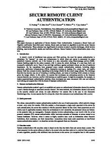
Fig.1. Distributed system architecture of the suggested reusable laboratory for remote experimentation.
Salaheddin Odeh: Building Reusable Remote Labs with Adaptable Client User-Interfaces
the Internet by the students. There are several difficulties accompanying such transformation: it is expensive and demands a lot of efforts, IT expertise, and skills; additionally, the designers usually lack the experience in hardware interfacing and developing client userinterfaces that consist of virtual instruments, which replicate the real equipment as closely as much. Later, it will be evident that the remote laboratory developed in this investigation presents an application product line. In this kind of reusability, the system is generalized to a common architecture which can be adapted in different ways for different customers. The experiment designer needs only to connect the experiment components and equipment such as capacitors, resistors, transistors, and function generators. With a configurable switching system of the lab server, then, she/he can map this connection structure to a configuration data structure. Once a student starts the client user-interface and logs-in into the lab server, the menu structure of the graphical user-interface builds and initializes itself automatically, using information stored in a configuration data structure of the experiment. For an electronic experiment, the experiment designer needs only to connect the experiment components and equipment such as capacitors, resistors, transistors, oscilloscopes. with a switch system of the lab server as shown in Fig.1. The switching matrix allows the test instrumentation to be connected to a number of test points on the experimental board course of an experiment. In a further step, she/he has to map the connection structure in a configuration data structure. The adaptability symbolizes a significant nonfunctional property of the system since the Web-based client user-interface initializes its menus and other interactive graphic objects from the configuration data structure initially sent by the lab server once a student remotely starts an experimental session. Throughout this paper, we will illuminate the ideas, the methodologies and the techniques behind our reusable remote lab prototype by an example of an engineering experiment of a common emitter amplifier. Despite the fact that the universal remote lab can be used for other more different complicated scientific and engineering laboratory experiments, we intentionally select a simple circuit to emphasize the methodology and the techniques developed in this research. Fig.2 illustrates an electronic circuit for measuring either the lower or upper cutoff frequencies. This experiment is one of the Electronic II laboratory course at the Faculty of Engineering at AlQuds University. For our purpose, it is sufficient to discuss the first part of the experiment, namely the
1001
lower cutoff frequency, whose main purpose is both to measure the lower cutoff frequency of a common emitter amplifier and to determine the lower cutoff frequencies due to each coupling and bypass capacitor. To make the experiment possible, various components and equipment are necessary such as resistors with values 1 KΩ, 1.5 KΩ, 2.2 KΩ, capacitors with values 0.001 µF, 0.22 µF, a transistor of the type 2N2222, a circuit board, DC dual power supply with a variable output between 0 V and 15 V, a signal generator and a dual trace oscilloscope.
Fig.2. Electronic circuit for measuring either the lower or the upper cutoff frequencies.
Section 2 reviews the different approaches of reusebased software engineering to put our system in the proper place in the reuse landscape. Section 3 discusses some of the state-of-the-art remote laboratories, addresses deficiencies in current labs and stresses the advantages and disadvantages of remote labs. After that, Section 4 exhibits the requirements essential to developing a reusable remote lab mediated to students or instructors. The requirements are both functional and non-functional. The system architecture, along with its design and implementation, is discussed in Section 5. We show the detailed design and implementation of the subsystems of the reusable lab and the integration of the whole system in Section 6. As the Web-based user-interface plays a central role in mediating the physical (real) experiment, Section 7 discusses the functionality of the user-interface in addition to various aspects of human-computer interaction, which must be taken into account while developing a usercentered user-interface[9] . Section 8 discusses a comparative evaluation through which we can determine how much our reusability approach was successfully implemented in designing and developing the reusable remote laboratory. Moreover, it deals with the usability of the
1002
adaptable Web-based client user-interface regarding various evaluation criteria such as transparency and orientation. Section 9 finalizes this contribution with a brief conclusion, and discusses outstanding issues and future directions for further investigation. 2
Reuse-Based Software Engineering
Currently, there is no doubt that systematic software reuse leads to more quickly and lower cost developed software with minimized risks. After Sommerville[10] , reuse-based software engineering can be divided into three categories: first, the application system reuse where the whole of an application system may be reused either by incorporating it without changing it into other systems or by developing application families; next, component reuse that makes it possible to reutilize components of an application from sub-systems to single objects, and finally a single well-defined object and function reuse. In order to categorize our system in the reuse landscape, it is significant to be familiar with the reuse techniques that have been developed over the past 20 years. Table 1[10] classifies the current reuse techniques. It is obvious that our system can be considered as an application product line. In other words, the common core of the application consisting of hardware and software is reused each time a new remote laboratory is required aside from the type of the experiment. The new development may involve specific component configuration, implementing additional components and adapting some of the components to meet new demands. 3
Overview of the State-of-the-Art Remote Laboratories
Wisher et al.[11] point out that the evolution of distance learning spread out over several stages. It began with the development of the postal service in 19th century. In the early and mid 20th century, radio and television became a means of providing educational instructions at home. In the early 1970s, the US Air Force’s Institute of Technology started a new distant teaching program based on telephones. This was abbreviated as “teleteach”, which involved commercial dialup telephones to provide limited duration instruction to remote locations. In more recent times, advanced technologies such as the Internet and personal computers have opened up the doors to new methods of providing distance learning. Although this research is mainly concerned with remote laboratories, it would help to make a comparative study with related approaches such as virtual laboratories and problem solving environments (PSEs) in escience area. Engineering and science courses normally
J. Comput. Sci. & Technol., Sept. 2010, Vol.25, No.5 Table 1. Reuse Landscape[10] Approach
Description
Design patterns
Generic abstractions that occur across applications are represented as design patterns that show abstract and concrete objects and interactions. Systems are developed by integrating components (collections of objects) that conform to component-model standards. Collections of abstract and concrete classes that can be adapted and extended to create application systems. Legacy systems that can be “wrapped” by defining a set of interfaces and providing access to these legacy systems through these interfaces. Systems are developed by linking shared services that may be externally provided.
Componentbased development Application frameworks Legacy system wrapping
Serviceoriented systems Application product lines
COTS integration Configurable vertical applications Program libraries Program generators
Aspectoriented software development
An application type is generalized around a common architecture so that it can be adapted in different ways for different customers. Systems are developed by integrating existing application systems (COTS: Commercial of the shelf). A generic system is designed so that it can be configured to the needs of specific system customers. Class and function libraries implementing commonly-used abstractions are available for reuse. A generator system embeds knowledge of a particular type of application and can generate systems or system fragments in that domain. Shared components are woven into an application at different places when the program is compiled.
include the laboratory components, which are essential to the learning process. Contemporary technologies and the Internet are essential for real laboratories or simulated laboratories (virtual laboratories) to enhance the learning/laboratory concept and theory. Remote and virtual laboratories are two effective techniques for the use of the Internet in engineering education. The technology involved in creating such online laboratories either allows a user to interact with an experimental setup located in another geographical location that is designated as a remote laboratory (R-Laboratories), or uses numerical simulation tools to emulate the behavior of an experimental system, i.e., a virtual laboratory[12] . V-laboratories are based on simulations of real systems. Where a simulation commonly replaces the real system[13-14] , virtual laboratories typically resort to simulation software such as MATLAB or LabView or specific applications. The
Salaheddin Odeh: Building Reusable Remote Labs with Adaptable Client User-Interfaces
latter approach is also known as PSE, which employs programming code to simulate the result of engineering or scientific problems using quite sophisticated numerical analysis, programming, and graphical tools. Best known of these PSEs is MATLAB, Pspice etc. A further two popular computer programs for handling algebraicanalytic mathematics (manipulating and displaying formulas) are Maple and Mathematica. Nowadays, PSE researches are aimed at disburdening users in their tasks to compute or simulate problems without complete computing and programming knowledge[15] . In this sense, the PSE provides an infrastructure for software for computational engineering and science[16] . PSEs can be run directly on a client host such as with Easy Java Simulation, but we could envisage server-side simulations or computing when specific software or calculus power is required and not easily available on client side. As an example is a distributed problem solving environment (PSE) for scientific computing[17] which supports users to solve partialdifferential-equation (PDE)-based problems in scientific computing. The system inputs a problem description and outputs a program flow, a C-language source code for the problem and also a document for the program. The modules are dispersed on distributed computers, and all the information is described by the Extensible Markup Language (XML), including the Mathematical Markup Language (MathML). This leads to easily binding the subsystems with each others. Another research project is a software tool called NAREGI-PSE, which aims to support the scientists’ work for scientific computer simulations in widely-distributed heterogeneous grid computing environment, and also to disburden application users to use applications by minimum knowledge of the applications and the grid environment[18] . It is to note that NAREGI is a Japanese National Grid Project started in 2003, whose chief aim is to develop a set of Grid middleware to serve as a basis for future e-Science. As already mentioned, remote laboratories are mainly based on controlling remotely located appliances, especially dedicated solutions for education. The general concept of remotely controlled devices has a longstanding history[19] , traced back to a master-slave teleoperator developed at Argonne National Laboratory in 1954[20] . However, the idea of establishing engineering education labs that can be remotely controlled is not really new. In 1991, Aburdene et al.[21] proposed an approach on sharing laboratories as the most expensive components of engineering education; they designated this kind of labs as the shared laboratory. The networked laboratory can be operated from a computer in a classroom, or from a computer at a remote location
1003
or another campus. More recent developments include, for example, • a bandwidth-efficient client-server model-based backend system written in Java for instructor-friendly remote monitoring and for carrying out various engineering and scientific course laboratories[22] ; • a networked control-system laboratory for the remote control of processes using SCADA (supervisory control and data acquisition) software enables the programmers to create distributed network control applications that have supervisory facilities and a humanmachine interface (HMI)[23] ; • a LabVIEW based remote laboratory called eDSPLab with a Web-based teaching environment for remote control of digital signal processors[24] ; • a blended learning approach in teaching “constrained time-delayed proportional-integral-derivative control” based on the “learning by doing” paradigm. This paradigm is supported by several e-learning tools such as Moodle for interactive electronic course materials and the virtual laboratory WebLAB that is created in the PHP programming language in cooperation with the MySQL database[25] ; • a hypertext-integrated remote laboratory for electrical measurement using Macromedia Flash environment[26] ; • a remotely accessible Matlab/Simulink based electrical drive experiments for hands-on education in electrical machinery and power electronics[27] ; • a Web-based laboratory for students in courses on feedback systems (iLab) using Java[28] , or real-time hardware experiments for modulation techniques developed with Visual Basic 6.0 and Measurement Studio 6.0[29] . Some remote laboratory systems have the property that they are reconfigurable via the client user-interface for enabling students to gain a better understanding of the experiment. The experiment elements are not dictated to students but rather more selectable, depending on their decisions or calculations required in an experiment[30] . Another example of such laboratories is a software-reconfigurable e-learning platform for power electronics courses[31] , aimed at realizing a platform capable of constructing a wide range of circuit topologies. This is enabled by a matrix switch module PXI-2529 from National Instruments Corporation, which can be used to connect any input to any output. This is different from those in [32-33] that allow students to construct converters and inverters only by using simple connections on a faceplate, rather, the testbed of the system presented in [31] can be remotely configured via software. A further example is a remote laboratory system for
1004
field-programmable gate array (FPGA) with an architectural design abstracted in a number of layers for allowing designers to reduce the overhead of setting up and operating a laboratory environment[34] . Using an automation tool for specifying a given hardware subsystem, a configuration file is created and then sent into the FPGA via a client application. The designer can visually observe the results by inspecting special components of the FPGA board through attached video-streaming displays. Apart from some present remote laboratories, whose designers implement some reusability features in its design, most current remote laboratories lack reusability. As an example for a system supporting reusability, a remote laboratory architecture referred as simPROCes[35] , which not only permits the teleoperation of simulators/real prototypes but also allows complete control applications to be remotely tested and validated. Additionally, it enables remote interaction with process simulators and/or real prototypes. Here, it is necessary to develop a tailor-made software interface in forms of a dynamic link library in order to couple the experiment prototype with the system. Another example is a remote lab prototype referred to as remote lab generator (RLGen) designed and implemented to explore and to demonstrate how the development process of remote labs can be simplified[36] . RLGen is based on Measurement Studio 6.0, which is a set of ActiveX for measurement and control equivalent in its features with LabVIEW. Various advantages are obtained through introducing remote labs as a complementary asset to traditional hands-on effective utilization of the lab equipment as lab equipment can be used all the time, the availability due to remote laboratories that allows geographical and temporal cutting up, safety if the experimentation to conduct is dangerous, staff cost savings since it is not necessary to keep the labs open at all times, better time scheduling for both students and lecturers, promoting of self-learning, and integration of disabled students when providing the lab with a human-machine system with the appropriate interaction devices tailored to their special needs. There are various deficiencies that remote labs are suffering from. For example, it is difficult to facilitate full functional access and remote control of a diverse range of software and hardware resources[37] . Another example is that designers have difficulties in presenting and mapping of the lecturer-led and group-work experiences of traditional campus-based laboratories on the Web-based client environment[38] . Callaghan et al.[39] declare that in contrast to traditional laboratories, Web-based remote access facilities were crude in nature with only a fraction of functionality, accessibility
J. Comput. Sci. & Technol., Sept. 2010, Vol.25, No.5
and flexibility of their campus-based counterparts, and their failure to fully utilize available hardware and software resources. 4
Reusable Remote Lab Requirements
During the process of requirements engineering, systems engineers establish the required system services and the constraints, under which the system must later operate. In many cases, the requirements themselves are the descriptions of the system services and constraints that are generated during the requirements engineering process. To discover the requirements, the system designer should, on the one hand, gather information about the proposed and existing systems and, on the other, distill the user and system requirements from this information, which can be in forms of documentation, system stakeholders and the specifications of similar systems. Several approaches are available to acquire the requirements such as interaction with stakeholders through interviews and observation, as well as using prototypes and scenarios. Scenarios are real-life examples of how a system can be used. However, there should be distinction between system and user requirements. While user requirements could take the form of statements in natural language plus diagrams of the services the system provides, and its operational constraints, system and software engineers realize system requirements as a structured document, which sets out detailed descriptions of the system functions, services and operational constraints, in addition to defining what should be implemented. Our major goal is to disburden the lab designers when building remote experimentations. Hasnim et al.[40] declare that there are some common tasks and processes in developing remote labs, which could be made as a scenario comprising the following tasks and activities: designing and connecting the experiment circuit by adding switching element such as a relay, designing and building the control programming in PC controller at the lab, designing, building and connecting the user-interface on students’ Web browsers to control programming of a PC controller, designing a related Web page for the experiment, and preparing the booking system with the use of database. Accordingly, we can roughly summarize the user requirements in the following. Requirement 1. Besides the measurement equipment with the switch system representing the core of the reusable remote lab, the experiment designer needs only to connect the experiment components such as capacitors, resistors, transistors, and, thereafter, she/he has to reflect this connection structure in a configuration
Salaheddin Odeh: Building Reusable Remote Labs with Adaptable Client User-Interfaces
data structure. The sequence of how these elements are connected with the switch system of the reusable remote lab is insignificant since the designer must map this arrangement into a configuration data structure. Requirement 2. Once the student starts the Webbased client user-interface and logs-in into the lab server, the menu structure of the graphical userinterface initializes itself from the configuration data structure in such a way that the user-interface adapts itself to the currently connected experiment. The Webbased client user-interface represents graphically all physical components and equipment needed in an experiment in order to enable students to manipulate them interactively. A virtual experimenting field serves as a circuit board for connecting the components and equipment with each other to obtain the desired experimentation circuit. In principle, the requirements should state the system function and the design should describe its operational process. However in practice, it cannot be denied that requirements and design are inseparable since system architecture may be designed to build up the system requirements, the system may inter-operate with other systems that generate design requirements, or the use of a specific design may be a domain requirement. For this reason, we present a system architecture suggested to fulfill the requirements for a reusable remote lab. Fig.1 illustrates the principal distributed system architecture designed to stress the requirements mentioned so far. The architecture applied to this system follows the simplest client-server architecture, the twotier client-server architecture organizing an application as a server and a set of clients. Section 5 describes indepth the whole distributed system and its subsystems and components regarding design and implementation. One of the various subsystems that plays a significant role in making reusable remote labs to a reality is the switch matrix. A 3 × 4 switch matrix (shown in Fig.3) can connect multiple inputs to multiple outputs organized as columns and rows. It is possible to connect any column to any number of rows and any row to any number of columns. At each intersection of a row and a column within a switch matrix, there is a switch. When the switch is closed, the row is connected to the column. Matrix size is often described as M rows by N columns (M × N ). As is obvious from Fig.2, the switch matrix used in this system is controllable, enabling us to connect all experimentation components and equipment with each other. As previously shown, all available experiment components and equipment can be selected through the menu system of the client user-interface and, later, the student decides where to place the experiment elements
1005
Fig.3. 3 × 4 switch matrix.
on the virtual board for further circuit manipulation. The menu system and other interactive elements on the client user-interface initialize themselves through the configuration and session tables, which should be formerly preconfigured by the experiment designer. Additionally, we have to formulize an additional system requirement, which emerges through the interaction of the users with the client user-interface. Requirement 3. Selecting a virtual experiment element and placing it on the virtual experimenting field cause the corresponding physical element on the lab server to be activated through connecting it with the switch system. As this element is now used, it cannot be selected again (see Fig.4), and its corresponding graphical element in the menu system appears as “unselectable” Due to this fact, it is necessary to provide the server
Fig.4. Graphical effects caused by placing of virtual components and equipments on the client user-interface.
1006
J. Comput. Sci. & Technol., Sept. 2010, Vol.25, No.5
lab with a hardware component designated here as an activating switch module, which translates the activities of selecting and placing of virtual components and equipment into real physical operations. The following example clarifies this mechanism. Example 1. As shown in Fig.4, after having selected and positioned the transistor T1 on the virtual experimenting field, the resistor R1 is selected from the menu to place it on the virtual experimenting field. Once the student completes these activities, these two electronic components (as shown in Fig.1) are connected with the switch matrix via the activating switch module by closing the switches Sj+1 , Sj+2 , Sj+3 for T1 and Sj+6 , Sj+7 for R1 . Regarding the client user-interface, the two menu items for the two electronic components are now no more selectable, as Fig.4 shows. 5
Distributed System Architecture and Its Design and Implementation In order to fulfill the user requirements explained
so far, we suggest the introduction of the distributed system architecture shown in Fig.1. The architecture applied to this system follows the simplest clientserver architecture, the two-tier client-server architecture, organizing an application as a server and a set of clients. The two-client architecture can take two forms: the thin-client and the fat-client. Architecturally, the reusable distributed system architecture proposed here follows the thin-client model because of the facts that all of the application processing and data management is actually carried out on the application server (lab server); the application is only responsible for running the representation software. Therefore, a system realized after this architecture allows the different users such as students and instructors to perform on real (physical) experiments remotely whenever they want and anywhere they are. Our application can be classified as an event-processing system due to the fact that the actions of the system depend on interpreting events occurring in the reusable lab environment. These events could be either the input commands of
Fig.5. Configuration and session data structure.
Salaheddin Odeh: Building Reusable Remote Labs with Adaptable Client User-Interfaces
the different users or variable changes of the experiment itself. The architecture proposes that our distributed application should be made of these components: The lab core serves as both a central control system and a mediator between the various subsystems within the reusable lab server. When the lab server starts, the lab core builds the dynamic configuration and session tables in accordance with the data stored in the experiment configuration database and the experiment session database. The experiment configuration database includes the way the experiment consisting of equipment and components is connected with the switch system, the way the various subsystems are connected with each other, and the way the adaptable client user-interface has to represent the experiment. The experiment designer needs only to connect the various experiment components and equipment with the activating switch module of the switch system. In a further step, the experiment designer has to reflect this arrangement in the configuration database via a configuration user-interface. Fig.1 illustrates from hardware-technical viewpoint how the experiment comprising components and equipment is connected with the switch activating module. Conversely, Fig.5 shows the configuration data structure from a softwaretechnical perspective. Every row of this data structure includes information about the experiment elements such as elements captions, their connections with the activating switch module. On the Web-based client user interface, the student positions and connects the experiment components and equipment virtually. Fig.6 illustrates the mechanism of how the client user-interface exchanges information with the lab server and, accordingly, how the latter controls the different subsystems of the remote laboratory. The client user-interface sends the structure of the wired-up elements on the virtual experimenting field along with the interactive commands operated on the virtual instrumentation equipment such as oscilloscopes to the lab core via the Internet. After receiving the new configurations, the lab core verifies the validity of the manipulated connections and seeks for prohibited connections such as GND with VCC that might damage the electronic equipment and components; afterwards in case of acceptable connections, it forwards these connections to the switch control responsible for connecting the experiment equipment and components with each other as desired. The GPIB control unit is not only responsible for the processing of the text data including commands that are operated interactively on the virtual instrumentation equipment sent by the client GUI, but it also converts the acquired data to a suitable IEEE-488 protocol in order to make it understandable
1007
by the IEEE-488-based equipment used in the experiment (see Fig.1 and Fig.6). Among the different software and hardware components contributing to make our system reusable is the dynamic configuration and session tables created at program start and initialized from the configuration and session databases of the lab server. Thanks to object-oriented programming techniques, programmers can realize such complicated data structures easily. After starting the lab server, the lab core builds these data structures according to what is stored in the experiment configuration and session databases. The experiment configuration database is needed every time an experiment is started, whereas the session database will be read only if an uncompleted experiment session must be continued. Mainly, the purpose of these dynamic tables is to manage the elements of the experiment that the student positions on the virtual circuit board, along with their connections. Hereafter, we are going to discuss the elements of the dynamic configuration and session tables. Most of these variables are used to set up the Web-based client user-interface. Two-Dimensional Index. As the name indicates, this data element has paired indices [i1 , i2 ]. The first index indicates a menu and the other a menu-item within it. Both are visualized on the Web-based client userinterface. As observed, every value for menu i1 might include more menu items i2 . While i1 determines the position of a menu in the menu-bar, i2 determines the location of a menu-item within this menu. For example in Fig.5, i1 might have value 0 for passive electronic elements such as resistors and capacitors, value 1 for simple active electronic elements such as transistors and diodes, value 3 for experiment equipment such as function generators and oscilloscopes. Theoretically, this menu system can be easily expanded to more than two levels through using n-dimensional vectorized indices. In fact, users prefer menu-driven user-interfaces with wide-shallow menu-trees. This preference has been determined through empirical studies such as that of Kigers experiment that dealt with different menu-tree forms[41] . It is evident through these studies that the breadth or number of items per level is preferred over depth or number of levels. Type. This parameter is especially useful for visual instruments. When the student places a graphic symbol of an instrument on the experimenting field, the system determines which virtual instrument must be activated on the instrumentation field (see Section 7). Activating Switches. If a virtual element is selected from a dynamic menu illustrated in Fig.7, the nodes of the corresponding physical element on the server side will be connected with the switch matrix for further
1008
J. Comput. Sci. & Technol., Sept. 2010, Vol.25, No.5
Fig.6. Dynamic of the distributed remote laboratory in the form of a state-transition diagram.
manipulation through closing the responsible switches of the activating switching module configured in the column “Activating switches” (Example 1). The lab core determines the switches to be activated through the equivalent node names assigned to them. For example it is obvious from Fig.5, the resistor R1 has two nodes R11 and R12 that are assigned to the switches Sj+6 and Sj+7 . State. It is a Boolean flag, whose value states whether the experiment element is used or not. Using a virtual element and placing it on the virtual circuit, the Boolean flag will be set to true. On the Web-based
client user-interface, the corresponding menu-item is no more active and cannot be selected because this element is currently in usage. Symbol. A symbol representing the appearance of the experiment element on the user-display, in addition to its caption and value. Caption. A descriptive title of the experiment element, such as R for resistors and C for capacitors etc. Value. If this variable value is not null, it includes either the value or the type of the electronic element used; for example, the string “2.2” in the case of a resistor or “2N2222” for a transistor etc.
Salaheddin Odeh: Building Reusable Remote Labs with Adaptable Client User-Interfaces
Unit. If the value of this variable is not null, it includes the unit of the electronic element described in the equivalent row such as KΩ (Kilo Ohm) in case of a resistor or µF (micro farad) in case of a capacitor. GPIB Address. An integer from 0 to 30 set to the GPIB address of the GPIB-based equipment. The IEEE-488 subroutines that are packaged as a dynamic library link (DLL) use this address to communicate with the desired equipment. The experiment designer has to assign all GPIB-based equipment included in a remote experiment a unique address that can be directly done through the physical equipment panel of every GPIB-based equipment. Reference. After connecting an experiment element with the switch matrix, which means that this element is also virtually placed on the experimenting field of the client user-interface, a reference (a pointer) to another data-row entry in the dynamic session table including information about the state of this element both on the client user-interface and within the lab server, will be created. The row information in the dynamic session table are: Position refers to the coordinates of the virtual experiment element on the experimenting field of the client user-interface. Direction represents the angle of the direction of an experiment element with reference to the vertical axis on the virtual experimenting field. Nodes’ Connections is a string containing the permitted connections of this element with others as a
1009
result of the interaction of the student with the remote experiment through the client user-interface. As an example (see Fig.5 and Fig.7), in the “Session data” table, the node R11 is connected with the node T11 of the transistor T1 . Similarly, the node R11 (resistor R1 ) is connected with the node OSCI 1 of the oscilloscope input 1. After sending the connected nodes of the virtual circuit by the client, the lab server extracts the connection information and then stores them in the table filed “Nodes’ connections” of the belonging experiment element. Afterwards, the lab core passes it to the e-validator for checking against undesired connection combinations, which might lead to damaging the experiment components and equipment. The e-validator uses a data-base embracing knowledge of forbidden circuit connections in forms of if-then rules, which are built of two parts: conditions and action. As an example, virtually connecting POWER1 and GROUND1 (see Fig.5) on the client GUI will be not accepted by the e-validator (see also Fig.1 and Fig.6). The lab core feeds back the student with the unexpected connections. Then, the checked data will be forwarded to the switch matrix for connecting the desired experiment elements with each other. The lab core undertakes the management and scheduling of the students’ accesses into the system. This is due to a scheduled database storing account information for every registered student. A student’s account stores the login name and password, results
Fig.7. Screen prototype of the adaptable Web-based client user-interface.
1010
and marks of the experiment quizzes and tests, schedule data of accessible time. When a student tries to access an experiment, the management and the schedule component examine whether she/he is allowed to access this according to a schedule time-table. Moreover, this component manages the registration procedures of the students for enabling them to execute the experiment. The entered data will be temporarily stored, verified by the experiment administrator, and then it will be stored in the database permanently. The system informs the students about the failure or the success of their registration attempts by email confirmations. If the login name and password entered by a student are correct, the lab server establishes a connection between the client and the remote lab. As the experiment designer, along with the course instructor, verifies and validates the recorded e-validator reactions against incorrect students’ operations on the experiment, it is important to have a component that records the students’ interactions with the userinterface. The recorded data is also useful for usability testing. A remote experiment can be on any topic in an engineering lab related to electric circuits or electronics and so on. From Fig.1, the inputs of the measurement equipment such as multimeters or oscilloscopes and the outputs of function generators for supplying the circuit with input signals can be connected with the experiment components through the switch matrix via the activating switch module. So far, it has been clarified how the experiment designer configures the experiment hardware and software. Measurement data acquired by oscilloscopes, multimeters or function generator signals must be sent to the Web-based client user-interface as well as control data operated on the virtual instruments of the client GUI. These are necessary to remotely teleoperate these equipment. They can be received from the adaptable Web-based client user-interface through the GPIB control unit (see Fig.1 and Fig.6) over GPIB (General Purpose Interface Bus), which is based on the IEEE-488 standard[42] . Fortunately, most of the current instrumentations such as oscilloscopes and multimeters are provided with control through PCI GPIB card and GPIB cable, allowing PCs to communicate with over 2000 instruments made by over 200 manufacturers. The main purpose of GPIB is to send information between two or more devices. Before any data is sent, the devices must be configured so that they could send the data in the proper order and according to the proper protocol[43] . The electrical specifications as well as the cables, connectors, control protocol, and messages required to allow information transfer between devices are defined by the IEEE-488 standard. For example, it is possible to
J. Comput. Sci. & Technol., Sept. 2010, Vol.25, No.5
connect up to 14 devices together by chaining IEEE488 cables from one device to the next. IEEE-488 supports data transfer at up to 1 MB/s. In addition to simple data transfers, the IEEE-488 standard defines a number of specialized commands for interface programming in the form of subroutines available as programming libraries for different programming languages such as C, Pascal, C#, Java. For this purpose, there are interface routines available as a dynamic link library called “ieee 32m.dll” through which we can send or receive data from a GPIB-based device. For example, the routine SEND(address, info, status) sends a command or data to a device. The parameter “address” represents the GPIB address of the GPIB-based equipment, which can be obtained from the dynamic configuration and session tables (see Fig.5); the parameter “info” is a command in forms of a string that can be sent to a GPIB device, for example “VAL1?” for returning the value shown on the primary display of the Fluke 45 Dual Display Multimeter, or “ACC” for measuring AC current etc. In Fig.6, during the state “Controlling the experimentation equipment by GPIB control unit” the GPIB control unit sends to the GPIB equipment IEEE.844 commands synthesized from what is received from the client GUI. The received data are interactive commands operated on the virtual instrumentation equipment of the client GUI such as oscilloscopes and multimeters. The control software uses the table element “2D-index” of the configuration and session table, which serves as a unique ID for every experiment element used in the remote experiment (see Fig.5) for determining the GPIB address of the virtually operated equipment. It is to note that a GPIB address can be assigned to GPIB-based equipment by using its interaction panel. 6
System Development and Implementation
Generally, it is difficult to resolve requirements and design uncertainties of research projects. For this reason, our system development follows the prototyping approach based on the iterative design and development approach[10,44] . In the iterative process, the stages: specification, design, development, and testing are not chained; rather interleaved and concurrent. The system containing software and hardware is developed in a series of increments with each including a new system functionality. Unlike most remote labs mainly dedicated for a particular experiment, our system is reusable by both physical (electronic) and software configuration. In other words, after connecting the experiment components and equipment with lab server, the experiment designer maps the physical experiment structure into the configuration data-structure.
Salaheddin Odeh: Building Reusable Remote Labs with Adaptable Client User-Interfaces
Building reusable software-ergonomic components either as standalone or integral components for designing user-interfaces is multidisciplinary which makes it difficult to design and to implement. It demands knowledge and skills from disparate science and engineering disciplines such as cognitive science in order to make remote environment usable and catch up with modern learning theories, education for the integration of remote laboratories activities in the students learning process, software engineering so that the imagined model can be implemented. To implement a system with these features, an advanced programming technique needs to be used such as C++, C# or Java, JavaScript or ActionScript which enable developers to easily translate the previously explained requirements into computer software. When developing and programming user interfaces, it is recommended to follow an interactive development system like Microsoft Visual Web Developer 2005 Express Edition in addition to these tools: Visual C# 2005 Express Edition[45] , Microsoft SQL Server 2005, Web Server: either IIS (Internet Information Service) or Apache, Web Development, and Adobe Flash CS3. Both .NET and Adobe Flash CS3 technologies include graphical user interface tools with rich libraries for user interface components, enabling data to be displayed in many forms. In this investigation, the development of the server side has been carried out using Visual C# 2005 Express Edition; whereas, we are using Adobe Flash CS3 with its ActionScript 3.0 to develop the adaptable client user-interface. ActionScript is the language we can use if we want to add more interaction features Flash applications and users or other systems. Such applications are often designated as Flash movies, which can be embedded in Web pages. To run applications movies, the Flash Player plug-in must be installed in Web browsers. The published state of a movie is how it would appear if viewed over the Web or with the Flash Player[46] . Published Flash movies have the Shockwave Flash extension “.swf”. SWF files can be viewed but not edited. To integrate ASP.NET with a Flash SWF file (the userinterface application) programmed in ActionScript 3.0, we are using XML (see next section). One of our primary goals is to imitate real equipment graphically as much as possible achieved with low cost and userfriendly Internet-accessible instrument what can be easily accomplished by using Adobe Flash CS3 environment. Callaghan et al.[47] point out that this is of great significance as it would allow the student to move seamlessly from virtual representations of test equipment in a remote laboratory environment to actual test equipment in a real laboratory and to be capable of using
1011
this equipment competently as a direct result of their online experiences. From a reusability viewpoint, the integration of such objects confirming to componentmodel standards falls in the category of componentbased engineering within the reuse landscape[10] . 7
Adaptable Web-Based Client User-Interface
The adaptable Web-based client user-interface is responsible for running the presentation software, which will be mediated by a conventional Web browser such as Microsoft Internet Explorer, Mozilla Firefox or Google Chrome. When Web-based user interfaces are designed, user-interface designers must take several human-computer interaction rules into account such as consistency of data display (labeling and graphic conventions), efficient information assimilation by the user, minimal memory load on user, compatibility of data display with data entry, flexibility for user control of data display, presentation of information graphically where appropriate, standardized abbreviations, presentation of digital values only where knowledge of numerical value is necessary and useful[9] . In the first design stage of a user-interface, the usage of simple screen sketches and key-screen prototyping might be important to ease obtaining the user-interface requirements. Simple screen sketches encourage users so that the user-interface concept can be illustrated by simple screen sketches (paper or on-screen) aimed at conveying the system concept to non-technical users; whereas key-screen prototyping focuses on key-screen prototyping. One reason why key-screen prototypes are suitable for developing user-interfaces in the early design stages is that they show users the design of the proposed system and allow them to evaluate and refine it; they can be also used for usability testing and heuristic review. They usually evoke strong reactions, generate early participation, and create momentum for the project. For example, a menu-driven user-interface may have one or two menu paths active, instead of all of menu paths envisioned for the final system. Before discussing the key-screen prototype of the adaptable Web-based client user-interface illustrated in Fig.7, it is necessary to clarify some terms of cognitive engineering necessary for designing user-interfaces. This will not only simplify distinguishing between the terms used in this paper, but it will also mediate the concept as well. Ergonomically, we have to distinguish between aspects of perceptive and cognitive ergonomics[48] . While the cognitive ergonomics relates to reasoning, memory and knowledge[49] , the perceptive ergonomics focuses on designing issues such as color, shape form, dimension and allocation, highlighting and so on.
1012
In this paper, we have focused only on the reuse features explained so far that should be taken into consideration when the user-interface is implemented. We hereby have highlighted the control elements of the user-interface such as those of the adaptable menu system, which will be initialized from the configuration data structure of the remotely located lab server. The initialization process begins as soon as an experimental session is started (see Fig.6). The dynamic menu includes menu-items created in conformity with what is stored in the configuration data structure. That is, the menu system of the adaptable user-interface is a graphical transformation of the configuration data structure. In the configuration data structure, the column variable “2D index” contains paired values about menus and their sub-menus. For example, in the paired variable with values (0, 1), the first value 0 is reserved for the menu-item “Passive Elements” and the second value 1 for the resistor R1 whose value is 82 KΩ. Furthermore, the paired values have another meaning; namely, they determine the position of the menu-item within the pull-down menu, as observed in Fig.5 and Fig.7. As already mentioned, we are using Adobe Flash CS3 to develop the client GUI. The dynamic menu is realized using the ActionScript class “ContextMenu” which provides runtime control over the items in the Flash Player context menu. Each ContextMenuItem object has a caption (text). For example, “R1 82 KOhm” that is displayed in the context menu, and a callback handler (a function) that is invoked when the menu item is selected, e.g., a function for uploading an image (symbol) and placing it on the experimenting field. To add a new context menu item to a context menu, we have to add it to the customItems array of a ContextMenu object. ContextMenuItem objects will be initialized from the configuration data structure (see Fig.5). Another example, the method my contextmenu.customItems.push (new ContextMenuItem (menu item caption, uploadSymbolHandler) adds a menu item with the text stored in the variable menu item caption with an associated callback handler function named uploadSymbolHandler. We can enable or disable specific menu items, make items visible or invisible, or change the caption or callback handler associated with a menu item. This is important because the menu items of used experiment elements must be disabled. ContextMenu objects can be assigned to button objects, in which main menu-items like “Passive Elements” are managed. Communication between the lab server programmed in C# (ASP. NET), and the client GUI realized as a Flash SWF file is achieved using XML. For example, in ActionScript 3.0, the client GUI (Flash application
J. Comput. Sci. & Technol., Sept. 2010, Vol.25, No.5
as SWF file uses the URLLoader class to load the XML file. XML files are requested through the URLRequest class. On the server side, we use XmlDocument class provided in the System.Xml namespace. The Load method of the XmlDocument class uses the static method Server.MapPath(PathOfTheXMLFile) to load the XML file into the object of the class XmlDocument. The XML file will be filled with desired data to exchanged with the client GUI. The static method Server.MapPath (“full path name”) is of great significance because we need to point to the XML file’s path, representing the full physical path of the XML file. Nodes of an XML file are created by means of both the class XmlNode and the XMLDocument method CreateNode. On the lab server side, every experiment symbol is stored in a file, whose name can be acquired from the configuration table. For example, the experiment element R1 is stored as R1.jpg. Such files are located on the server side along with another text files (for example R1.txt) containing coordinates of connectable pixel areas inside the pixel image for wiring up purposes (see Fig.7). An ActionScript function needs this information to enable students to wire up the test points of the virtual circuits interactively. Thereby, the coordinate text files are necessary for being able to determine the connectable areas of experiment icons. Currently, such symbol elements and their connectable area information are created manually. In the future, this activity can be automated through a special graphic editor. As shown in Fig.1, the e-validator mediates between the lab core and the switch control. It uses the field “nodes’ connections” sent after every confirmed work step on the client GUI, for carrying out a consistency check; once the check passes, the received data will be used to control the real experiment. Accordingly, the e-validator feeds the student back with the success or failure. The students can use the instrumentation equipment placed as symbols on the experimenting filed to activate virtual instruments for obtaining more detailed information acquired from the remotely physical instruments. Once a virtual instrument is visualized, it will be ready to present data on its virtual display. The instrumentation equipment symbols on the experimenting field can be connected with test points of the virtual circuit as necessary in the course of an experiment. As Fig.7 shows, in the experimenting field, instrumentation equipments are shown as graphic symbols that can be only used for connecting purposes with other experiment elements in the experimenting field. In the instrumentation interaction field, the student gets a detailed representation of the instrumentation equipments being
Salaheddin Odeh: Building Reusable Remote Labs with Adaptable Client User-Interfaces
activated in the experimenting field, where she/he operates interactively on the virtual instrumentation equipments such as oscilloscopes or multimeters. Operating on an input control object of a virtual instrumentation device with detailed representation, specific data as strings consisting of device ID, control object ID and the adjusted value are produced and will be then sent to the laboratory server. The GPIB control unit processes the received string and then converts it to a corresponding GPIB command. The end of Section 5 illuminates how the GPIB control unit converts the received commands that are operated on the virtual instruments of the client GUI to IEEE.844-based commands, which can be understood by GPIB instruments. 8
Usability Testing of the Reusable Remote Laboratory
A comprehensive usability testing[50] is necessary not only for revealing the strengths and weaknesses of the reusability approach developed in this investigation, but also for evaluating the usability of the adaptable Web-based client user-interface regarding various evaluation criteria such as transparency, orientation. To evaluate how much the reusability approach was successfully implemented in designing and developing the reusable remote laboratory, subjects (the remote experiment designers) interact with the system in order to build a remote experiment. In this evaluation, the task “building a laboratory experiment” by means of the achieved reuse environment or by following conventional steps to construct remote experiments, serves as independent variables; whereas the evaluation criteria such as the time needed to build a remote laboratory experiment, number of errors occurring while building the experiment environment, are the dependent variables. It will be possible to measure the differences between the two ways according to what extent the reusability engineering features realized in this investigation accelerate the building process of a remote laboratory environment and disburden remote experiment designers in their tasks to build remote laboratories. In order to test the usability of the adaptable Webbased client user-interface and to find out the appropriateness of the client Web-based user-interface to be as a mediator between the physical experiment and students via the Internet, subjects (the students) interact with the system via the Web-based client user-interface and have to solve several scenarios. Students carry out the experiment in two sessions. • Session 1: carrying out the experiment using the reusable remote laboratory through its adaptable user-interface. • Session 2: carrying out the conventional
1013
experiment (face-to-face). One reason for two different environments are used is that the obtained result should be comparative. In this evaluation, the different environments along with the different scenarios represent the independent variables or factors. The name comes from that these terms are independent from each other; whereas the evaluation criteria such as transparency, navigation serve as dependent variables. In statistical experiments, dependent variables can be determined subjectively or objectively. Subjective magnitudes are necessary when usability engineers are interested in finding out the personal sensing, feeling or impression of the users while interacting with a software system. Transparency, confidence, fun etc. are examples of subjective variables; whereas the objective magnitudes can be obtained through the students’ interaction with the system, e.g., the number of keystrokes or scenario time. The raw data of the experiments were handled statistically by using the Student’s test (t-test)[51] and then analyzed by SPSS[52] . The statistical outcome should be analyzed and reviewed by the usability engineers and the system designers, so that the final results helped revise and optimize the design of the reusable remote laboratory. As a useful means for comparing mean values of two sets of numbers, usability engineers have the opportunity to select between either the Student’s test (t-test)[53] or one-way ANOVA, through which a comparison can be carried out, providing us with a statistic for evaluation exposing the statistical significance of the difference between two means. 9
Conclusion
We have seen how we can design and implement a reusable remote lab with an adaptable client userinterface dedicated for various types of scientific and engineering experiments. It is always necessary to review some contributions concerned with the development of remote laboratories with modern software engineering characteristics such as software reusability and modular design. Remote labs in our design philosophy aim to relieve experiment designers in their tasks of building laboratory experiments in such a way that they only need to connect the various experiment components and equipments with the activating switch module of the switch system of the lab server. Subsequently, they have to map the hardware arrangement in the configuration database via a configuration user-interface. When an experiment session is started by initiating the adaptable Web-based client user-interface, the menu structure of the graphical user-interface builds itself autonomously from the configuration data structure, adapting itself to the currently connected
1014
experiment. On the user-interface, all physical components and equipments needed in an experiment are graphically represented, enabling students to manipulate the virtual experiment elements interactively. As Table 1 shows, there are various categories of reuse philosophies such as design patterns, component-based development, application frameworks. It is obvious that our system can be considered as an application product line. As previously noticed, this paper is concerned not only with the reusability of the hardware and software regarding requirements, design and implementation, but also with the detailed development of virtual experiment elements consisting of software and ergonomics structures as well. In this context, we have highlighted how we can create and develop the virtual instruments, and the control elements of the userinterface such as those of the adaptable menu system, which will be initialized from the configuration data structure of the remotely located lab server. The initialization process begins as soon as an experimental session is launched. References [1] Callaghan M J, Harkin J, McGinnity T M, Maguire L P. Paradigms in remote experimentation. International Journal of Online Engineering (iJOE), 2007, 3(4). [2] Jonassen D, Wang S. Acquiring structural knowledge from semantically structured hypertext. Journal of Computer-Based Instruction, 1993, 20(1): 1-8. [3] Alessi S M, Trollip S R. Multimedia for Learning: Methods and Development. Allyn & Bacon, Massachusetts, 2001, pp.16-47. [4] Rigby S, Dark M. Designing a flexible, multipurpose remote lab for the IT curriculum. In Proc. the 7th Int. Conf. Information Technology Education, New York, USA, Oct. 19-21, 2006, pp.161-164. [5] Mougharbel I, Hajj A E, Artail H, Riman C. Remote lab experiments models: A comparative study. International Journal of Engineering Education, 2006, 22(4): 849-857. [6] Gravier C, Fayolle J, Bayard B, Ates M, Lardon J. State of the art about remote laboratories paradigms — Foundations of ongoing mutations. International Journal of Online Engineering (iJOE), 2008, 4(1). [7] Yan Y, Liang Y, Du X, Hassane H S, Ghorbani A. Putting labs online with Web services. IT Professional, 2006, 8(2): 27-34. [8] Hasnim H, Abdullah M Z. Remote lab generator: A software tool for lab lecturer. In Proc. Int. Conf. Electrical Engineering and Informatics, Institut Teknologi Bandung, Indonesia, Jun. 17-19, 2007, pp.558-560. [9] Shneiderman B, Plaisant C. Designing the User Interface: Strategies for Effective Human-Computer Interaction. Addison Wesley Longman, 2004. [10] Sommerville I. Software Engineering. Addison Wesley, 2007, pp.415-438. [11] Wisher R A, Sabol M A, Moses F L. Distance learning: The soldier’s perspective. AEI Special Report 49, May 2002. [12] Almgren R C, Cahow J A. Evolving technologies and trends for innovative online delivery of engineering curriculum. International Journal of Online Engineering (iJOE), 2005, 1(1).
J. Comput. Sci. & Technol., Sept. 2010, Vol.25, No.5 [13] Patel S H, Sobh T M. Online automation & control: An experiment in distance engineering education. International Journal of Online Engineering (iJOE), 2006, 2(3). [14] Candelas Her´ıs F A, Jara Bravo C A, Torres Medina F. Flexible Virtual and Remote Laboratory for Teaching Robotics. Current Developments in Technology-Assisted Education, FORMATEX, 2006. [15] Houstis E N, Rice J R. Parallel ELLPACK, a Development Environment and Problem Solving Environment for High Performance Computing Machines. Programming Environments for High-Level Scientific Problem Solving, Gaffney P, Houstis E N (eds.), Amsterdam: North-Holland, 1992, pp.229-241. [16] Kawata S, Boonmee C, Fujita A, Nakamura T, Teramoto T, Hayase Y, Manabe Y, Tago Y, Matsumoto M. Visual Steering of the Simulation Process in a Scientific Numerical Simulation Environment. Enabling Technologies for Computational Science, Houstis E, Rice J (eds.), Kluwer Academic Pub., 2000, pp.291-300. [17] Kawata S, Fuju H, Sugiura H, Saitoh Y, Hayase Y, Teramoto T, Kikuchi T. A distributed problem solving environment (PSE) for scientific computing. In Proc. the 1st Int. Conf. e-Science and Grid Computing (e-Science 2005), Melbourne, Australia, Dec. 5-8, 2005, pp.470-477. [18] Kanazawa H, Itou Y, Yamada M, Miyahara Y, Hayase Y, Kawata S, Usami H. Design and implementation of NAREGI problem solving environment for large-sale science grid. In Proc. the 2nd IEEE Int. Conf. e-Science and Grid Computing (e-Science 2006), Amsterdam, The Neitherlands, Dec. 4-6, 2006, 102. [19] Esche S K, Chassapis C, Nazalewicz J W, Hromin D J. An architecture for multi-user remote laboratories. World Transaction on Engineering and Technology Education, 2003, 2(1): 7-11. [20] Malinowski A, Dahlstrom J, Febles Cortez P, Dempsey G, Mattus C. Web-based remote active presence. In Proc. the 2000 ASEE Annual Conference, Saint Louis, USA, Jun. 1921, 2000, Session 3232. [21] Aburdene M F, Mastascusa E J, Massengale R. A proposal for a remotely shared control systems laboratory. In Proc. the ASEE 1991 Frontiers in Education Conference, West Lafayette, USA, Sept. 21-24, 1991, pp.589-592. [22] Mittal A, Gupta C, Gupta A. Addressing the bandwidth efficiency, control, and evaluation issues in software remote laboratory. IEEE Transactions on Industrial Electronics, June 2008, 55(6): 2326-2333. [23] Lazar C, Carari S. A remote-control engineering laboratory. IEEE Transactions on Industrial Electronics, June 2008, 55(6): 2368-2375. [24] Barrero F, Toral S, Gallardo S. eDSPLab: Remote laboratory for experiments on DSP applications. Internet Research, 2008, 18(1): 79-92. [25] Huba M, Simunek M. Modular approach to teaching PID control. IEEE Transactions on Industrial Electronics, Dec. 2007, 54(6): 3112-3121. [26] Ferrero A, Salicone S. Towards a hypertext of electric measurement: Different approaches for an on-line, remote, didactic lab. IEEE Transactions on Instrumentation and Measurement, 2007, 56(1): 89-94. [27] Bogosyan S, Turan A, Wies R W, Gokasan M. Development of remotely accessible Matlab/Simulink based electrical drive experiments. In Proc. IEEE International Symposium on Industrial Electronics, Vigo, Spain, Jun. 4-7, 2007, pp.29842989. [28] Viedma G, Dancy I J, Lundberg K H. A Web-based linearsystems iLab. In Proc. the 2005 American Control Conference Proceedings, Portland, USA, June 8-10, 2005, pp.5139-5144.
Salaheddin Odeh: Building Reusable Remote Labs with Adaptable Client User-Interfaces [29] Das S, Sharma L N, Gogoi A K. Remote communication engineering experiments through internet. International Journal of Online Engineering (iJOE), 2006, 2(1). [30] Odeh S, Abu Shanab S. Remote experimentation using augmented reality. Ubiquitous Computing and Communication Journal, 2009, 4(1), ISSN 1994-4608. [31] Wang S C, Liu Y H. Software-reconfigurable e-learning platform for power electronics courses. IEEE Transactions on Industrial Electronics, June 2008, 55(6): 2326-2424. [32] Trivedi M, McShane E A, Vijayalakshmi R, Mulay A, Abedinpour S, Atkinson S, Shenai K. An improved approach to application-specific power electronics education-switch characterization and modeling. IEEE Trans. Educ., Feb. 2002, 45(1): 57-64. [33] Williams J M, Cale J L, Benavides N D, Wooldridge J D, Koenig A C, Tichenor J L, Pekarek S D. Versatile hardware and software tools for educating students in power electronics. IEEE Trans. Educ., Nov. 2004, 47(4): 436-445. [34] Indrusiak L S, Glesner M, Reis R. On the evolution of remote laboratories for prototyping digital electronic systems. IEEE Transactions on Industrial Electronics, Dec. 2007, 54(6): 3069-3077. [35] Hassan H, Dom´ınguez C, Mart´ınez J M, Perles A, Albaladejo J. Remote laboratory architecture for the validation of industrial control applications. IEEE Transactions on Industrial Electronics, Dec. 2007, 54(6): 3094-3102. [36] Hasnim H, Abdullah M Z. Remote lab generator (RLGen): A software tool using auto-generating technique to develop a remote lab. International Journal of Online Engineering (iJOE), 2007, 3(4). [37] Callaghan M J, J. Harkin J, T.M. McGinnity T M, L.P. Maguire L P. Integrated architecture for remote experimentation. In Proc. IEEE International Conference on Systems, Man and Cybernetics, Washington DC, USA, Oct. 5-8, 2003, pp.4822-4827. [38] Esche S K, Chassapis C, Nazalewicz J W, Hromin D J. A Scalable system architecture for remote experimentation. In Proc. the 32nd ASEE/IEEE Frontiers in Education Conference, Boston, MA, USA, Nov. 6-9, 2002, pp.T2E 1-6. [39] Callaghan M J, Harkin J, McGinnity T M, Maguire L P, Collaborative environment for remote experimentation. In Proc. Int. Conf. Microelectronic Systems Education, Anaheim, California, Jun. 1-2, 2003 pp.157-162. [40] Hasnim H, Abdullah M Z. A study on the potential of using remote labs for e-learning engineering courses in Malaysian universities. In Proc. 7th WSEAS International Conference on Applied Computer Science, Venice, Italy, 2007, pp.140144. [41] Kiger J I. The depth/breadth trade-off in the design of menu-driven user-interfaces. International Journal of Man-
1015
Machine Studies, 1984, 20(2): 201-213. [42] Caristi A J. IEEE-488: General Purpose Instrumentation Bus Manual (professional and technical series). Academic Press, 1989. [43] “CEC 488 programming and reference, Part number 370966A01”, 2003. [44] Faison T, Component-Based Development with Visual C#. John Wiley & Sons, 2002. [45] Deitel H M. Visual C# 2005: How to Program. Prentice Hall, 2005. [46] Deitel H M. AJAX, Rich Internet Applications, and Web Development for Programmers. Pearson Education, FORMATEX, Inc., 2008. [47] Callaghan M J, Harkin J, McGinnity T M, Maguire L P. Client-server architecture for remote experimentation for embedded systems. International Journal of Online Engineering (iJOE), 2006, 2(4). [48] Johannsen G. Mensch-Maschine-Systeme. Berlin: Springer, 1993. [49] Anderson J R. Cognitive Psychology and Its Implications. New York: Worth Publishers 2000. [50] Rosson M B, Carroll J M. Usability Engineering: ScenarioBased Development of Human-Computer Interaction, Morgan Kaufmann Publishers, 2002. [51] Johnson R A, Bhattacharyya G K. Statistics: Principles and Methods. Wiley, 2000. [52] Pallant J. SPSS Survival Manual. Open University Press. 2004. [53] Gardner P L. Discusses assumptions of the t-test. Scales and Statistics: Review of Educational Research, 1975, 45: 43-57.
Salaheddin Odeh received his Master’s degree in electrical engineering, from the University of Stuttgart and the Ph.D. degree from the University of Kassel; both universities are in Germany. He is currently an assistant professor in the Department of Computer Engineering. His research interests include software engineering, control engineering, robotics, advanced programming, operating systems, human-computer interaction, and multimedia. In 1999, for his doctoral thesis, he was the recipient of the first prize of the Association of German Engineers (VDI) of Northern Hesse in Germany for the best technical-scientific research.