quirements such as application-dependent packet handling, customer-specific ... virtual routers which act as stand-alone routers despite sharing a common .... braiding enables each trie node to swap its left child node and right child ...... [17] S. Kumar, M. Becchi, P. Crowley, and J. S. Turner, âCAMP: Fast and. Efficient IP ...
Building Scalable Virtual Routers with Trie Braiding Haoyu Song, Murali Kodialam, Fang Hao, T.V. Lakshman Bell Labs, Alcatel-Lucent {haoyusong, muralik, fangh, lakshman}@alcatel-lucent.com
Abstract—Many popular algorithms for fast packet forwarding and filtering rely on the tree data structure. Examples are the trie-based IP lookup and packet classification algorithms. With the recent interest in network virtualization, the ability to run multiple virtual router instances on a common physical router platform is essential. An important scaling issue is the number of virtual router instances that can run on the platform. One limiting factor is the amount of high-speed memory and caches available for storing the packet forwarding and filtering data structures. An ideal goal is to achieve good scaling while maintaining total isolation amongst the virtual routers. However, total isolation requires maintaining separate data structures in high-speed memory for each virtual router. In this paper, we study the case where some sharing of the forwarding and filtering data structures is permissible and develop algorithms for combining tries used for IP lookup and packet classification. Specifically, we develop a mechanism called trie-braiding that allows us to combine tries from the data structures of different virtual routers into just one compact trie. Two optimal braiding algorithms are presented and the effectiveness is demonstrated using the real world data sets.
I. I NTRODUCTION The growing need to satisfy diverse networking requirements such as application-dependent packet handling, customer-specific policy-based routing, disruption-free new protocol deployment, etc., has led to increased interest in building virtual networks [1]–[4] that can satisfy these diverse needs while sharing a common network infrastructure for costefficiency. Deploying these virtual networks requires the use of virtual routers which act as stand-alone routers despite sharing a common physical platform with other virtual routers. An ideal virtualization goal is to achieve good isolation among the virtual routers while also achieving high scalability so that a large number of virtual routers can concurrently run on the same physical platform. Unfortunately, these two goals of isolation and scaling have conflicting system needs. Isolation sets limits on the sharing of physical resources whereas scaling requires the limited resources to be efficiently shared. An example of the need for differing routing functions on the same platform, akin to virtualization, is the case of IPv4 to IPv6 migration [5], [6]. The dual-stack router needs to support both IPv4 and IPv6 routing simultaneously. Another example of the need for differing routing functions on the same platform is for the case of layer 3 MPLS Virtual Private Networks (L3 VPNs) [7]. L3 VPNs allow enterprises to securely achieve any-to-any reachability amongst all their sites while outsourcing their routing needs to the service provider. The service provider’s edge router needs to maintain a private routing table for each VPN customer. With the rapid growth in
the VPN market, the memory required for storing VPN routing tables has become a critical resource and a key bottleneck in provisioning new customers [8]. As the need of virtualized networks grows, a physical router is expected to support a few tens and possibly even hundreds of virtual routers with each having its own forwarding table and routing protocol instances (e.g. Juniper routers currently are reported to be capable of supporting 16 virtual routers [9]). Scaling to these numbers poses serious challenges to the router design, especially when complex packet classification and deep packet inspection need to be implemented. A critical resource that limits the scaling is the limited amount of high-speed memory used for caching the packet forwarding and filtering data structures, which account for a large portion of the system cost and power consumption. It is straightforward to partition the available memory and allocate a fraction to each virtual router. This simple partitioning has the benefit of isolating the memory usage of the virtual routers. However, it is not efficient and severely limits the scalability for two reasons: (1) It is difficult to determine the right fractions to allocate to each virtual router when each virtual router has different forwarding table size and that can change dynamically. (2) The overall memory consumption is linear in the number of virtual routers as well as in the size of the memory required for each virtual router. Fu and Rexford show that just 10 moderate sized forwarding tables use up to 120Mb of SRAM [10]. Scaling to larger numbers makes the memory consumption prohibitive. If the isolation requirement can be relaxed, memory usage can be considerably reduced by consolidating the individual packet forwarding and filtering data structures into a combined one. Two key router functions allows such optimization: longest prefix matching and packet classification. IP forwarding tables consist of a set of prefixes and their associated next hop. To determine the next hop for an incoming packet, the longest prefix matching (LPM) of its destination address is conducted. The majority of the LPM algorithms, including all variants of multi-bit trie [11]–[15] and the pipelined architecture [16]–[18], use data structures derived from the basic binary trie. Packet classification, needed for policy-based routing and network security, performs a range matching operation on several fields of an incoming packet’s header. The matching operation is used to retrieve a matching rule and an action to be performed on the packet. Because of the need to match on multiple fields, packet classification is inherently more complex than the LPM operation. Numerous efficient algorithms
2
Table A 0* 1* 01* 001*
Table B 0* 110* 111*
have two virtual routers with the aforementioned prefix tables, we need the memory to be able to hold 12 trie nodes since each trie has 6 nodes. This scheme, where the high-speed memory linearly adds up as the total required physical memory, clearly does not scale well. To this end, we address the following problem: given a number of binary tries, how can we compactly store them in a combined data structure which minimizes the overall memory consumption and still allows correct lookups into each of the individual binary tries?
TABLE I S AMPLE PREFIX TABLES
A 0 B 0 D
a 1
1
0 C
b
c 1 d
1 E 1 F
0 e (a)
B. Related Work 1 f
(b)
Fig. 1. Binary tries for the sample prefix tables. (a) for Table A and (b) for Table B. The dark nodes are valid prefix nodes
have been proposed for packet classification and many of these algorithms also use the tree data structure. For example, the HiCuts [19] and HyperCuts [20] algorithms build a decision tree on the packet header fields. Some other decompositionbased algorithms such as RFC [21] and BV [22] work on the lookups on each individual header field first and then combine the results to find the final matching rule. The single field lookup can be done using a trie data structure. Since packet classification is known to be memory intensive, sharing the memory among the different header fields in one classifier and across the classifier data structures for different virtual routers can have substantial scaling benefits. We introduce a new mechanism called trie braiding that can be used to build a compactly shared data structure. Trie braiding enables each trie node to swap its left child node and right child node freely. The changed shape is remembered by a single bit at each trie node. This extra degree of freedom gives us the opportunity to achieve the optimal memory sharing performance when combining the tries. II. BACKGROUND A. Trie-based LPM in Virtual Routers The trie-based LPM algorithms start from a simple binary trie formed by the IP prefixes. The description of the trie construction and lookup can be found in [10]. Figure 1 illustrates the binary tries generated from the sample prefix tables in Table I. When multiple virtual routers are hosted on the same physical router, with each virtual router needing its own packet filtering and forwarding-table lookup capabilities, the physical router’s memory needs to be shared or be allocated amongst the virtual routers. For the trie-based algorithms, the number of trie nodes can be taken as a measure of the memory needed. If packet-forwarding data structures are stored separately, the memory size can become prohibitive preventing significant scaling of the virtual router capability. As a toy example, if we
A scheme that inserts all the prefixes belonging to the different virtual routers into one single trie is described in [10]. We call this scheme the (prefix) overlap scheme since it exploits prefix overlaps between the multiple prefix tables to reduce memory needs. To perform correct lookups in each individual trie, each prefix node in the trie needs to store a bitmap that indicates which virtual router’s trie the prefix belongs to. Since many trie nodes are shared, the final trie size can be significantly smaller than the sum of the overall sizes of the individual tries (which would be the case if the tries are individually maintained for every virtual router). The scheme is illustrated in Figure 2(a) for the example virtual routers. The total number of trie nodes with combining is 9, which is smaller than the 12 nodes needed otherwise. However, this scheme does not necessarily lead to memory savings, since each trie node that is a valid prefix for any virtual router needs to store the next hop information. The large trie node sizes resulting from this can offset the gains stemming from the reduction in the total number of trie nodes. To mitigate this problem, the authors in [10] propose the use of leaf pushing where all valid prefixes are pushed to be at the trie leaves, so that only the leaf nodes need to store the next hop information and the internal trie nodes do not incur this storage overhead. This is illustrated in Figure 2(b). However, leaf pushing has the problem that it creates new trie nodes that increase the memory consumption in some cases. This is the case in the example shown where the number of trie nodes is now just one less than the case when the two tries are stored separately. Also, since the leaf pushing trie is a full tree, 50% of the trie nodes are leaf nodes which still need to store the next hop information. The overlap scheme in [10] works best when the original tries have a similar structure. In the worst case, this scheme may not lead to any memory reduction. Consider the following example where for one virtual router table all prefixes start from ‘0’ while for another virtual router table all prefixes start from ‘1’. For this case the overlap scheme does not lead to any gains over storing the tries separately. The graph theory used in this paper builds on the extensive literature on tree algorithms [23]. More specifically, the algorithms we developed use dynamic programming-based techniques like the ones used for computing edit distance between trees [24] as well as the isomorphism detection algorithms in [25]. However, the optimization objective and
3
IV. O PTIMAL T RIE B RAIDING A LGORITHMS A. Problem Formulation
(a)
(b)
Fig. 2. Overlap scheme for virtual routers (a) without leaf pushing (b) with leaf pushing 0,1
0,1
0,0
0,0
0,0
0,0
We now consider the problem of minimizing the amount of memory to store k tries using trie braiding. We take a first step by considering just two binary tries T1 and T2 . The notation we use is listed in Table II. Ti vi hi ri P (vi ) CL (vi ) CR (vi ) d(vi ) t(vi ) n(vi ) Ni (h) Ui (h)
Tree i Generic node in tree Ti Depth of tree Ti Root of tree Ti Parent of node vi ∈ Ti Left child of node vi ∈ Ti Right child of node vi ∈ Ti Depth of vi ∈ Ti . Subtree rooted at vi ∈ Ti . Number of nodes in t(vi ). Set of nodes at depth h in Ti . Number of isomorphisms at depth h in Ti . TABLE II N OTATION
0,0
Fig. 3. Node sharing using trie braiding. The numbers are the braiding bit value for the original tries
the performance criteria used by our algorithms are different from the typical performance metrics used in the literature. III. T RIE B RAIDING We develop trie braiding as a mechanism to accomplish a more compact combining of the individual tries, even when the individual tries are not initially similar. By using a single braiding bit in a trie node, we can reverse the meaning of its child pointers: when the bit is set, the left pointer represents the ‘1’ branch and the right pointer represents the ‘0’ branch. We call this mechanism braiding because we can freely swap the left and right sub-tries of any trie nodes. Trie braiding allows us to adjust the shape of dissimilar tries and make them as similar as possible so that the number of shared nodes is maximized (thereby reducing memory needs) upon merging. To illustrate, in Figure 1(b), if we swap node a’s child nodes and node c’s child nodes, the resulting trie will become similar to the first trie. Now we can merge these two tries into one and get a new trie as shown in Figure 3. This trie has only 7 nodes. Also, for this case, leaf pushing will not increase the total number of nodes. Once the value of the braiding bits is determined, to insert a prefix in the trie (or to lookup a given IP address), we do the following: Starting from the root node, we examine each prefix bit sequentially. We compare this bit with the braiding bit at the current trie node. If they are equal, we follow the left pointer; otherwise, we follow the right pointer. The braiding bits are unique to each virtual router. When we merge tries from multiple virtual routers, the braiding process gives us a useful tool for minimizing memory usage by maximizing the node sharing.
Definition 1: A mapping M of T2 to T1 is a function that takes a subset of nodes in T2 and maps it one-to-one to a subset of nodes in T1 . ½ v1 for some v1 ∈ T1 M (v2 ) = ∅ Otherwise If M (v2 ) = v1 , then we denote this as M −1 (v1 ) = v2 . If there is no node that is mapped onto to some node v1 , then we denote this as M −1 (v1 ) = ∅. Definition 2: A permissible mapping is a mapping that maintains the precedence relationship. Specifically, a mapping M from T2 to T1 is permissible if both conditions are true: M (r2 ) M (v2 )
= r1 = v1 ⇒ M (P (v2 )) = P (v1 ) for v2 6= r2
(1) (2)
The set of permissible mappings is denoted by M. Definition 3: For a given permissible mapping M ∈ M, we let S1 S2
= {v1 : M −1 (v1 ) = ∅} = {v2 : M (v2 ) = ∅}.
We define the cost of mapping c(M ) to be c(M ) = |S1 | + |S2 |. Let θ represent the number of nodes in Ti that have a nonempty mapping. That is: θ
=
|T1 | − |S1 | = |T2 | − |S2 | 1 (|T1 | − |S1 | + |T2 | − |S2 |) . (3) = 2 The total number of nodes in the combined tree is therefore: 1 θ + |S1 | + |S2 | = (|T1 | + |T2 | + |S1 | + |S2 |) 2 1 = (|T1 | + |T2 | + c(M )) (4) 2
4
Since |T1 | and |T2 | are fixed, minimizing the total number of nodes in the combined tree is equivalent to finding the minimum cost mapping. Definition 4: We define the distance ∆(, ) between two trees, T1 and T2 , as ∆(r1 , r2 ) = min c(M ). M ∈M
More generally, given some node v2 ∈ T2 and v1 ∈ T1 , we use ∆(v2 , v1 ) to represent the distance between the two subtrees rooted at node v1 and node v2 . It is easy to see that ∆(v1 , v2 ) = ∆(v2 , v1 ). Definition 5: If ∆(r1 , r2 ) = 0, then T1 and T2 are called top-down isomorphic and we represent this as T1 ∼ T2 . The study of top-down isomorphisms was initiated by [26]. A polynomial-time algorithm for identifying top-down isomorphism was given in [24] in the context of identifying programs with similar syntax. Unlike our case where the nodes are unlabeled, the syntax tree has labeled nodes. See [23] for an exhaustive description of tree isomorphism algorithms. While there are polynomial time algorithms to check if two trees are top-down isomorphic, these algorithms do not extend directly to the problem of determining the minimum cost mapping if ∆(r1 , r2 ) 6= 0. Our next result, which is straightforward to prove, states that if T2 and T3 are top-down isomorphic, then the distances of any tree T1 to T2 and T3 are identical. Lemma 1: Let T2 ∼ T3 , then ∆(r2 , r1 ) = ∆(r3 , r1 ). The next result gives a simple lower bound on the distance between two trees. Lemma 2: Given two trees T1 and T2 with n1 and n2 nodes respectively, ∆(r1 , r2 ) ≥ |n1 − n2 |. Proof: Assume n1 ≥ n2 . Even if all the nodes in tree T2 are mapped to tree T1 there will still be n1 − n2 nodes in tree T1 that will not be mapped. The following result also holds for all the permissible mapping. Lemma 3: For any permissible mapping M from T2 to T1 , d(v2 ) = d(M (v2 )). Proof: We prove this by contradiction. If d(v2 ) 6= d(M (v2 )), when we recursivley apply Condition (2), we get M (r2 ) 6= r1 , which contradicts with Condition (1). The problem of determining the minimum-cost permissible mapping can be formulated as an integer linear programming problem but it does not lead to an efficient solution procedure. Instead, we use a dynamic programming-based mapping algorithm (BRAID) to determine the minimum cost feasible mapping in Section IV-B. In Section IV-C, we give an
algorithm (FAST-BRAID) that cuts the running time as well as memory requirement for running BRAID by identifying isomorphic subgraphs. B. BRAID: A Dynamic Programming Algorithm The input to the optimal braiding algorithm are the two binary trees and the output from the algorithm are • A minimum-cost mapping M from T2 to T1 . • A braiding bit B(v2 ) for each non-leaf node v2 ∈ T2 which indicates the straight mapping (B(v2 ) = 0) or the twisted mapping (B(v2 ) = 1) applied to node v2 ’s two child nodes. Computing Mapping Costs: Given tree Ti rooted at ri , our goal is to determine ∆(r1 , r2 ). This can be achieved from the bottom up. We can compute the value of ∆(v1 , v2 ) by considering the following two mapping possibilities: • A straight mapping, where the left (right) child of v2 is mapped to the left (right) child of v1 ; • A twisted mapping, where the left (right) child of v2 is mapped to the right (left) child of v1 . We use φS (v2 , v1 ) to denote the cost of a straight mapping and φT (v2 , v1 ) to denote the cost of a twisted mapping. Assume that we have already computed the value of ∆( , ) for the child nodes of v1 and v2 , we have φS (v2 , v1 ) = ∆(CL (v2 ), CL (v1 )) + ∆(CR (v2 ), CR (v1 )) (5) φT (v2 , v1 ) = ∆(CL (v2 ), CR (v1 )) + ∆(CR (v2 ), CL (v1 )) (6) The non-existent child node is set to ∅. We have the special case: n(Cy (v1 )) if Cx (v2 ) = ∅ n(Cx (v2 )) if Cy (v1 ) = ∅ ∆(Cx (v2 ), Cy (v1 )) = 0 if Cy (v1 ) = Cx (v2 ) = ∅ where x and y can be either L or R. The value of ∆(v2 , v1 ) is the minimum of these two mapping costs: ∆(v2 , v1 ) = min{φS (v2 , v1 ), φT (v2 , v1 )}.
(7)
In addition to computing the value of ∆( , ), we also keep track of whether the straight or the twisted mapping attained the minimum. Let ½ S(v2 , v1 ) =
0 1
if φS (v2 , v1 ) ≤ φT (v2 , v1 ) if φS (v2 , v1 ) > φT (v2 , v1 )
(8)
We start computing the values of ∆ from the leaves and work the way up to the root, described as follows. Computing Leaf Weights: Let hm = min{h1 , h2 }. From Lemma 3, we know that nodes with depth greater than hm will be mapped to ∅. We compute the weight of the leaves of the trees as follows: For i = 1, 2, w(vi ) = n(vi ) ∀vi such that d(vi ) = hm .
(9)
5
We can now define the distance between two nodes v1 ∈ T1 and v2 ∈ T2 (both at depth hm ) as ∆(v1 , v2 ) = |w(v2 ) − w(v1 )|.
(10)
This follows directly from the proof of Lemma 2. The equality is due to the fact that at least one of the nodes is leaf. Iterating from the Leaves: Once we finish computing the values of ∆(v2 , v1 ) for all nodes at depth hm , we start the iterations from depth hm − 1 and move up to the root one depth at a time. At depth h, for every v2 ∈ T2 with d(v2 ) = h and every v1 ∈ T1 with d(v1 ) = h, we compute ∆(v2 , v1 ) using Equation 7. Once we reach depth 0, ∆(r2 , r1 ) is the minimum mapping cost. Determining the Minimum-cost Mapping: Now the algorithm starts to determine the minimum-cost mapping for each node in T2 . It starts from r2 and uses S( , ) to obtain the optimal mapping. In addition, the algorithm outputs the braiding bit B(v2 ) for each node v2 . If B(v2 ) = 0 then the straight map is optimal at node v2 ; If B(v2 ) = 1, then the twisted map is optimal at node v2 . Figure 4 shows the computation of ∆( , ) for the trees shown in Figure 1. The computation is from depth 3 to depth 0. All subtree distances (i.e. the minimum mapping costs) between the two trees are logged in a matrix for each depth. At depth 3, it easy to see ∆(F, e) = 0 and ∆(F, f ) = 0. The matrix at each other depth is calculated from the matrix at one depth deeper. When all the matrices are in position, the second phase is to determine the minimum-cost mapping. At depth 0, we know the minimum cost 2 is achieved by the twisted mapping (i.e. M (b) = C and M (c) = B), so B(a) = 1. We then examine the matrix at depth 1 for the above mappings. ∆(B, c) = 2 is achieved by the twisted mapping (i.e., M (d) = D), so B(c) = 1. Note that b and C are both leaf nodes, so the mapping orientation does not matter. We simply let B(b) = 0. We continue this process down to depth 3 and finally get the optimal mapping as shown in Figure 3.
e f F 0 0 depth
d D 1 E 2
3
2
b c B 3 2 C 0 3 1
a A 2 0
Fig. 4. Illustration of BRAID on the trees in Figure 1. The value in the boxes represents the the value of ∆( , ). The shaded box means the corresponding mapping is twisted
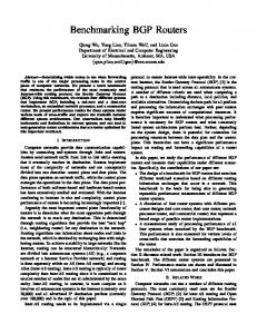
The complexity of BRAID is dominated by the first phase where we have to compute the value of ∆(v2 , v1 ) for all v2 and v1 that are at the same depth. It is easy to see the running time (as well as the temprory storage) of the optimum braiding algorithm is: Ãh ! m X O |N1 (h)||N2 (h)| h=1
If the trees are small, this running time might be acceptable. But for the large tries that typically arise in packet lookups,
35000 30000 # of isomorphic subtrees
25000
# of nodes
20000 15000 10000 5000 0 0
4
8
12
16
20
24
28
32
trie level
Fig. 5. The number of isomorphic subtrees versus the number of nodes at each trie depth
the running time as well as the amount of memory consumed in storing the intermediate results will be excessive. Figure 5 shows the number of nodes at each depth in a trie built from a BGP prefix table. Some depth contains more than 30,000 nodes, which means when we run BRAID on two such trees, the matrix at this depth alone would require almost one billion entries. C. FAST-BRAID: Braiding with Isomorphism Detection We improve the performance of BRAID significantly both in terms of running time as well as memory consumption by identifying the isomorphic subtrees during the course of running the algorithm. The motivation for developing FAST-BRAID is the result in Lemma 1. Consider the computation of ∆(v2 , v1 ) and ∆(v2 , v10 ) where v2 ∈ T2 and v1 , v10 ∈ T1 are at the same depth. Since t(v1 ) ∼ t(v10 ) ⇒ ∆(v2 , v1 ) = ∆(v2 , v10 ). if we can identify the fact that t(v1 ) ∼ t(v10 ), then we need to compute the value of ∆( , ) only once. The performance improvement with this modification is determined by • Time taken to identify isomorphisms. • The number of isomorphic subtrees at each depth. Identifying isomorphisms in a tree can be done in linear time. Since we identify isomorphisms in each tree separately, there is no quadratic penalty associated with identifying isomorphisms. If there are a large number of isomorphic subtrees, then the amount of computation will be decreased significantly. Figure 5 shows the number of distinct isomorphic subtrees at each depth in the trie built from the same BGP prefix table. The maximum number of distinct isomorphic subtrees at a depth is 4,000, which is an order of magnitude smaller than the maximum number of nodes. This property holds for all the real world prefix tables we examined. Therefore, we expect a significant reduction in computation time as well as memory requirement. Generating Labels: We use the technique developed by Hopcroft and Tarjan [25] in their linear time algorithm for tree isomorphism to keep track of the nodes with isomorphic subtrees. This is done using a labeling scheme. Since we have
6
binary trees, we use a simple indexing mechanism to determine the labels instead of the lexicographic sorting algorithm developed in [25]. We first process each tree separately. The routine COMPUTE LABEL (Ti , h) gives a label L(v) to each node at depth h of tree Ti such that for vi , vi0 ∈ Ni (h) L(vi ) = L(vi0 ) ⇐⇒ t(vi ) ∼ t(vi0 ). In other words, two nodes will be given the same label if and only if the subtrees rooted at those two nodes are isomorphic. It is easy to prove the following Lemma, which sets the fundation for the labeling process. Lemma 4: Two trees are isomorphic if and only if their subtrees are isomorphic. That is: t(vi ) ∼ t(vi0 ) ⇐⇒ t(CL (vi )) ∼ t(CL (vi0 )) and t(CR (vi ) ∼ t(CR (vi0 )) or t(CL (vi )) ∼ t(CR (vi0 )) and t(CR (vi ) ∼ t(CL (vi0 )) Consider the labeling of nodes in T1 . We start off at the bottom most depth. All leaves get a label of 1. The missing leaves are given a label of 0. We then move up to the next depth. At each depth, we initialize an array Ah to store the labels. The size of Ah = [Ui (h+1)]2 and all the array elements are set to 0. We process one node at a time and consider the labels of its left and right children denoted by L1 and L2 respectively. The array index for node v, denoted by p(v), is ½ p(v) =
•
2 1 φS (j, k) = ∆(γL2 (j), γL1 (k)) + ∆(γR (j), γR (k)) 2 1 2 φT (j, k) = ∆(γL (j), γR (k)) + ∆(γR (j), γL1 (k))
(11) (12)
The value of ∆(j, k) is the minimum of these two values ∆(j, k) = min{φS (j, k), φT (j, k)}.
(13)
In addition to computing the value of ∆( , ), we also keep track of whether the straight or the twisted label mapping attained the minimum distance. Let ½ 0 if φS (j.k) ≤ φT (j, k) (14) S(j, k) = 1 if φS (j, k) > φT (j, k) The rest of the algorithm is almost the same as the BRAID algorithm. The only difference is that when we determine the braiding bit for a node v2 , we have to consider three factors: S(L(v2 ), L(M (v2 ))), τ2 (v2 ), and τ1 (M (v2 )). The braiding bit ofLnode v2Lis calculated as B(v2L ) = S(L(v2 ), L(M (v2 ))) τ2 (v2 ) τ1 (M (v2 )) (We use to denote the XOR operation). The label distance matrices are shown in the right side of Figure 6. Similarly, the computation and storage complexity of FASTBRAID is Ãh ! m X O U1 (h) U2 (h) h=1
L1 Ui (h + 1) + L2 L2 Ui (h + 1) + L1
if L1 ≤ L2 if L1 > L2
The integer variable ω (with initial value 1) tracks the label that will be given to the next new isomorphism. If Ah [p(v)] = 0, a new isomorphism is identified and it is given the label ω. Ah [p(v)] is updated with ω and ω is incremented to be used for the next isomorphism. In addition, for each node we also track: •
we have already computed the value of ∆( , ) for the child nodes. Then
The labels of the two children associated with a given i label ω in tree Ti , which are stored in γLi (ω) and γR (ω), i i where γL (ω) ≤ γR (ω). The label order of the node v’s two children, which is stored in the variable τi (v) for v ∈ Ti . The value of τi (v) = 1 if the left child’s label is greater than the right child’s label for the node v. τi (v) = 0 otherwise.
We illustrate the labeling process in the left side of Figure 6 for the trees in Figure 1. In the figure, ∅ represents an empty tree; (j, k) means the left subtree has a label j and the right subtree hash a label k. Determining the Distance: In the BRAID algorithm, we computed ∆(v2 , v1 ). In the FAST-BRAID algorithm, we have to compute the value of ∆( , ) for two labels, each from a different tree. This computation is done as follows: Let j and k denote two labels at depth h in trees T2 and T1 respectively. We use φS (j, k) to denote the cost of a straight mapping and φT (j, k) to denote the cost of a twisted mapping. Assume that
depth 3
depth 2
depth 1
depth 0
label tree 2 tree 1 ø (ø,ø) ø (ø,ø) 0
0
1
ø (1,1)
0
0
2
ø (1,2) (ø,ø) 0
1
2
0 1 0 0 1 1 1 0
1
ø (ø,1) (ø,ø) 1
(,)
0 1 0 0 3 1 2 1 2 1 2
1
ø (ø,ø) (ø,1) 0
1
2
ø (1,2)
ø (2,3)
0
0
1
1
0 1 2 0 0 1 4 1 4 3 2 2 1 0 3 0 1 0 0 6 1 6 2
Fig. 6. Illustration of the labeling procedure in FAST-BRAID. The labels for the two tries and the distance between the labels are shown.
D. Combining Multiple Trees So far we have dealt with the problem of combining two trees. If we want to combine more than two trees then the running time of the optimal algorithm grows exponentially with the number of trees. For example, if there are three trees T1 , T2 , T3 and we want to map T2 and T3 onto T1 . At depth h we have to consider the cost of mapping every pair of nodes (v2 , v3 ), where v2 is at depth h of tree T2 and v3 is at depth h of tree T3 , with every node v1 at depth h of tree
7
T1 . This makes the optimum algorithm prohibitively expensive to run. Therefore, we use an incremental approach where we first merge T1 and T2 and then merge T3 onto this combined tree. Though it is not optimal, the running time only goes up linearly in the number of trees. The choice of the order in which the trees are merged can make a difference to the solution, but from our testing, we find that the difference in the merging order is negligibly small for all our tests (i.e. the difference on resulting trie sizes is smaller than 0.01%). We show the results of combining multiple trees in Section V. V. A LGORITHM E VALUATION It is difficult to evaluate the performance of our algorithm due to the lack of realistic virtual router forwarding tables. We can only collect several routing tables from a variety of sources including the Route Views Project [27] which has snapshots of the latest BGP tables from several backbone locations around the Internet. The problem with these tables is that all of them contain the similar set of prefixes, therefore the tries built from these tables are of the similar shape. In this case, the simple overlap scheme as in [10] is sufficient and our algorithm cannot bring enough improvement to justify its preprocessing overhead. However, we speculate the real virtual routers in future will contain very different prefixes, hinted by the current IP VPN service where each customer works on its own address space with a different aggregation scheme. This is the case our algorithm can really stand out. For this reason, the best thing we can do is to simulate this scenario by manipulating the avaiable tables.
into 16 equal sized sub-tables. We then select a varying number of sub-tables to merge. As the number of sub-tables increases, the number of prefixes in use also increases. Hence, in all the three cases, the total number of trie nodes increases. However, the trie nodes for the trie-braiding algorithm increases at a much slower pace. B. Performance on IPv6 Tables Since large IPv6 tables are not available, we use the method described in [28] to synthesize IPv6 tables with sizes comparable to the IPv4 tables that they are based on. This serves as a reasonable substitute for the IPv6 tables expected in the future. The prefix length in the IPv6 tables span from 16 to 64. With these tables we perform the same experiment as we did for the second experiment with IPv4 tables. As with the IPv4 tables, we observe that trie braiding leads to significant reductions in memory needs. We see this in Figure 8. However, note a significant difference from the IPv4 case. The overlap sharing scheme with leaf pushing uses much more trie nodes than the separate storage scheme (for which leaf pushing is not necessary). This is because the most IPv6 prefixes are much longer than IPv4 prefixes. With the same number of prefixes, the IPv6 trie is much sparser. A significant number of nodes do not have two child nodes; hence leaf pushing creates too many new trie nodes. This fact shows that the overlap scheme with leaf pushing is not suitable for sparse tries as in the case of IPv6. However, the optimal trie-braiding algorithm still generates much smaller tries even with the leaf pushing – it achieves 65% node reduction over the separate storage scheme. 1.E+07 9.E+06
In our first experiment, we randomly partition the oix BGP table, which contains 290K prefixes, into k (2 ≤ k ≤ 16) equal sized sub-tables. We count the total number of trie nodes for three cases: (1) store these table separately in k binary tries, (2) use the overlap scheme in [10] to collapse k tries to one trie, and (3) use the optimal braiding algorithm to collapse k tries to 1 trie. For the latter two cases, we also consider the trie size with and without leaf pushing. The results are shown in Figure 7(a). Note that even when the number of sub-tables varies, the total number of prefixes remains the same because of the partitioning of the prefix set to create the sub-tables. Hence, the overlap scheme always results in a constant number of trie nodes. However, when the number of sub-tables becomes larger, the number of trie nodes becomes larger for the separate storage scheme and smaller for the optimal braiding algorithm. When the number of sub-tables is 16, the trie-braiding algorithm reduces the trie size by a factor of 3.6 and 10, in comparison to the overlap sharing scheme and the separate storage scheme. This shows that triebraiding can achieve a very significant reduction in high-speed memory needs for critical packet-forwarding data structures and enhance virtual router scaling. Similar results are obtained in a second experiment, as shown in Figure 7(b). Here the as1221 BGP table is partitioned
8.E+06 total trie nodes
A. Performance on IPv4 Tables
separate overlap w/o leaf pushing overlap w/ leaf pushing braid w/o leaf pushing braid w/ leaf pushing
7.E+06 6.E+06 5.E+06 4.E+06 3.E+06 2.E+06 1.E+06 0.E+00 2
Fig. 8.
3
4
5
6
7 8 9 10 11 12 13 14 15 16 # of original tries
Performance Comparison on Different Number of IPv6 tries
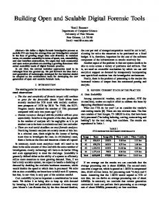
C. Performance on Packet Classification Filter Sets Since available real packet classification filter sets are small, to evaluate the performance of our algorithm on packetclassification data structures, we use the ClassBench tool [29]. We use it to synthesize three types of filter sets: FW, ACL, and IPC. Each filter set has 10K filters and each filter is defined by the usual five-tuple IP header fields. These filter sets are synthesized to have the structure of the real seed filter sets. For each filter set, we construct four tries for the four fields of source IP address, destination IP address, source port, and destination port. Note that in the filter sets, the two port fields
8 2.5E+06
1.6E+06 separate overlap w/o leaf pushing overlap w/ leaf pushing braid w/o leaf pushing braid w/ leaf pushing
1.2E+06 total trie nodes
total trie nodes
2.0E+06 1.5E+06 1.0E+06 5.0E+05
2
3
4
5
6
7 8 9 10 11 12 13 14 15 16 # of original tries
(a) oix, k partitions and combine k tries Fig. 7.
total trie nodes
3.E+05
Fig. 9.
4.0E+05
2
3
4
5
6
7 8 9 10 11 12 13 14 15 16 # of original tries
(b) as1221, 16 partitions and combine k tries
Performance comparison on different number of IPv4 tries
are typically defined as ranges. We convert these ranges into prefixess using standard means. We combine the four tries using the different combining schemes discussed before. We also combine all the 12 tries together. This mimics a virtual router that hosts all the three packet classification filter sets. The performance comparison is shown in Figure 9. Observe that the optimal node sharing algorithm using trie braiding reduces the trie size by up to 30%. Since packet classification is memory intensive, this is a significant reduction.
2.E+05
1.E+05
separate overlap braid
8.0E+05
0.0E+00
0.0E+00
0.E+00
separate overlap w/o leaf pushing overlap w/ leaf pushing braid w/o leaf pushing braid w/ leaf pushing
FW
ACL
IPC
all
216873 198083 143372
26888 24926 22904
19853 17790 15860
263614 236076 167033
Performance Comparison on Packet Classification Filter Sets
D. Discussion The overall memory consumption of the data structure is calculated as product of the trie size and the trie node size. Since each virtual router incurs one extra bit in each trie node, one may argue that for a large number of virtual routers, the braiding bits may result in large trie node size that negates the trie size reduction effect. In practice, the memory used to store the trie data structure works in burst mode. For example, the fastest QDR SRAM runs with burst sizes of 2 or 4. Given the typical bus width of 36 bits, this means that each memory access retrieves 72bits or 144-bits of data from the memory. If the information stored does not sufficiently fill the burst data, the unused bits are wasted anyway. Fortunately, the unused bits are enough to store the braiding bits for 16 to 32 virtual routers. When the
number of virtual routers is so large that one data burst cannot accommodate all the braiding bits, one can use two bursts of data to store the braiding bits. By carefully distributing the bits into two data bursts, for each trie node access, one needs to only read out one data burst according to the virtual router id. Another solution is to partition the virtual router into groups, with each group containing 16 or 32 virtual routers. The braiding algorithm is then just applied to each group of virtual routers. From the above evaluation, we observe that this method can achieve a two-fold gain in storage in comparison to the separate storage scheme. For example, as shown in our experiments, a 36-Mbit QDR SRAM can store the trie data structure for 16 virtual routers using the trie braiding algorithm. However, if the the simpler overlap scheme is used, a 72-Mbit SRAM is needed for the same set of virtual routers. Even worse, if the tries of the virtual routers are separately stored, a 144-Mbit SRAM is needed. The savings in high-speed memory consumption of our algoirthm directly translates into lower system costs, lower power dissipation and smaller board footprint. All these are highly desirable characteristics for high performance virtual routers. Another issue to be considered is throughput. Since multiple tries are merged into a single trie, all lookups in the original tries need to be now performed on one trie. Will this negatively affect the lookup throughput? This question is not unique to our scheme. If a router does not have a separate memory module for each virtual router (and this is the most likely case), the memory bandwidth always needs to be shared by the virtual routers regardless of the data structure used. When the packets from different virtual routers are served in some interleaved fashion, the aggregated packet lookup rate is determined by the overall memory bandwidth. A fully pipelined architecture can support one lookup per clock tick. The shared lookup data structure with a smart packet scheduler not only guarantees the minimum lookup rate for each virtual router but also is flexible enough to adapt to fluctuations of the packet arrivals without wasting the memory bandwidth. This is another advantage over the separate storage scheme. Another question that arises is incremental prefix updates
9
for virtual routers. A solution is to apply the prefix insertions and deletions directly to the combined trie. Like other triebased solutions that require tree topology optimization, the braided trie can be re-computed over a longer period of time in order to minimize the trie size. In order to enforce the logical isolations on top of the shared resource, the router hyperviser needs to set an upper bound on the number of prefixes each virtual router can support. Therefore, one virtual router cannot grow arbitrarily and deprive memory resource of the others. Such bounds can be adjusted dynamically between all the participate virtual routers, adapting to the actual system requirement. VI. C ONCLUDING R EMARKS Efficient resource sharing while maintaining the logical isolation is an important design issue for virtual routers. In this paper we present the trie braiding scheme and the optimal braiding algorithms to maximize the memory sharing for trie-based packet forwarding and filtering data structures. The experiments on real data set show our algorithms are highly effective on memory reduction without compromising the throughput and update performance for scalable virtual routers. Trie-braiding is applicable whenever the data structure involves multiple trees, no matter for one router or for multiple virtual routers. In addition to the virtual router lookup and packet classification applications, trie braiding can also be used for other tree compaction applications. For example, it can be used to compress a single binary prefix trie. For this, one uses a deterministic method to partition the prefix set into multiple subsets. A binary trie is constructed for each subset. Then the braiding algorithm is run over these tries to generate a single shared trie. To perform a lookup in this trie, the address is first classified using the same method to determine its subset id. The subset id is then used to address the trie-braiding bit in each trie node. A very simple case is where the first address bit is used to classify the prefixes into two subsets. This effectively enables us to collapse the left and right sub-tries together. This simple compacting can lead to a significant memory saving. While in this paper we have only considered combining tries from the root nodes, nothing precludes us from mapping the root node of one trie to any node of another trie. This means that we can attach a fixed prefix to all the prefixes in a table. In some case, this can result in better memory savings. However, finding an efficient algorithm to determine the optimal solution for this more general mapping problems is a topic for future investigation. Trie-braiding can also be extended to merge trees with arbitrary fanouts, where each node can swap places with any sibling nodes. As a special case, multi-bit trie is often used for faster trie lookups. It is straightforward to convert a braided binary trie to a multi-bit trie. Another method is to convert each binary trie to a multi-bit trie first and then merge them to one multi-bit tire using the braiding algorithm. It is interesting to see which one can result in better performance.
R EFERENCES [1] N. Feamster, L. Gao, and J. Rexford, “How to Lease the Internet in Your Spare Time,” ACM Computer Communication Review, Jan. 2006. [2] “Global Environment for Network Innovations,” http://www.geni.net, 2006. [3] J. Turner, “A Proposed Architecture for the GENI Backbone Platform,” in ACM ANCS, 2006. [4] A. Bavier, N. Feamster, M. Huang, L. Peterson, and J. Rexford, “In VINI Veritas: Realistic and Controlled Network Experimentation,” in ACM SIGCOMM, 2006. [5] J. Curran, “IPv4 Depletion and Migration to IPv6,” http://www.rmv6tf.org/, 2008. [6] E. Nordmark and R. Gilligan, “RFC 4213: Basic Transition Mechanisms for IPv6 Hosts and Routers,” http://www.ietf.org, 2005. [7] E. Rosen and Y. Rekhter, “RFC 2547: BGP/MPLS VPNs,” http://www.ietf.org, 1999. [8] C. Kim, A. Gerber, C. Lund, D. Pei, and S. Sen, “Scalable VPN Routing via Relaying,” in ACM SIGMETRICS, 2008. [9] Juniper, “Intelligent Logical Router Service,” http://www.juniper.net/solutions/literature/white papers, 2004. [10] J. Fu and J. Rexford, “Efficient IP Address Lookup with a Shared Forwarding Table for Multiple Virtual Routers,” in ACM CoNEXT, 2008. [11] M. Degermark, A. Brodnik, S. Carlsson, and S. Pink, “Small Forwarding Tables for Fast Routing Lookups,” in ACM SIGCOMM, 1997. [12] S. Nilsson and G. Karlsson, “IP Address Lookup using LC-Tries,” IEEE Journal on Selected Areas in Communications, June 1999. [13] V. Srinivasan and G. Varghese, “Faster IP Lookups Using Controlled Prefix Expansion,” in ACM SIGMETRICS, 1998. [14] W. Eatherton, G. Varghese, and Z. Dittia, “Tree Bitmap: hardware/software IP Lookups with Incremental Updates,” ACM SIGCOMM Computer Communication Review, 2004. [15] H. Song, J. Turner, and J. Lockwood, “Shape Shifting Tries for Faster IP Lookup,” in IEEE ICNP, 2005. [16] J. Hasan and T. N. Vijaykumar, “Dynamic Pipelining: Making IP Lookup Truly Scalable,” in ACM SIGCOMM, 2005. [17] S. Kumar, M. Becchi, P. Crowley, and J. S. Turner, “CAMP: Fast and Efficient IP Lookup Architecture,” in ACM/IEEE ANCS, 2006. [18] W. Jiang and V. K. Prasanna, “Beyond TCAMs: An SRAM-based MultiPipeline Architecture for Terabit IP Lookup,” in IEEE INFOCOM, 2008. [19] P. Gupta and N. McKeown, “Packet Classification using Hierarchical Intelligent Cuttings,” in IEEE Hot Interconnects, 1999. [20] S. Singh, F. Baboescu, G. Varghese, and J. Wang, “Packet Classification using Multidimensional Cutting,” in ACM SIGCOMM, 2003. [21] P. Gupta and N. McKeown, “Packet Classification on Multiple Fields,” in ACM SIGCOMM, 1999. [22] T. V. Lakshman and D. Stiliadis, “High Speed Policy-based Packet Forwarding using Efficient Multidimentional Range Matching,” in ACM SIGCOMM, 1998. [23] G. Valiente, “Algorithms on trees and graphs,” Springer-Verlag, 2002. [24] W. Yang, “Identifying Syntactic Differences Between two Programs,” Software-Practice and Experience, Vol. 21(7), 739-755, 1991. [25] A. Aho, J. Hopcroft, and J. Ullman, “The Design and Analysis of Computer Algorithms,” Addison-Wesley, 84-86, 1974. [26] S. Selkow, “The Tree-to-tree Editing Problem,” Information Processing Letters, Vol. 6(6), 184-186, 1977. [27] “Route Views Project,” http://www.routeviews.org/. [28] M. Wang, S. Deering, T. Hain, and L. Dunn, “Non-random Generator for IPv6 Tables,” 12th IEEE HotInterconnects, 2004. [29] D. Taylor and J. Turner, “ClassBench: A Packet Classification Benchmark,” in IEEE INFOCOM, 2005.