211 Bulletin of the New Zealand Society for Earthquake Engineering, Vol. 49, No. 2, June 2016
BUILDING TYPOLOGIES AND FAILURE MODES OBSERVED IN THE 2015 GORKHA (NEPAL) EARTHQUAKE Dmytro Dizhur1,2, Rajesh P. Dhakal3, Jitendra Bothara4 and Jason M. Ingham5 (Submitted March 2016; Reviewed April 2016; Accepted May 2016) ABSTRACT Nepal is one of the most earthquake-prone countries in the world, and at the same time is one of the most economically deprived. On 25 April 2015 mid-western Nepal was hit by the devastating Gorkha earthquake measuring Mw 7.8 with the epicentre located 76 km north-west of Kathmandu. The earthquake was followed by a series of aftershocks, with the most significant occurring on 12 May 2015 with Mw 7.3 and an epicentre located north-east of Kathmandu. The earthquake and the associated aftershocks resulted in the destruction of half a million buildings, leaving millions of people homeless and causing a loss of more than $3.5 billion (USD) to the housing sector alone. Approximately 9,000 people were killed and over 23,000 people were injured - mostly due to damaged or collapsed buildings. A number of documents have been published pertaining to general observations following the 2015 Gorkha earthquake and aftershocks. Here the common building typologies and related failure modes observed during inspection surveys by the authors who were part of the various reconnaissance teams following the earthquakes are summarised. A brief background on the 2015 Gorkha earthquake is provided with an outline of the tectonic environment and seismological background of Nepal and a brief summary of previous earthquake activities in the region is presented. Common construction practices identified during the reconnaissance are illustrated and briefly explained to provide context to the observed earthquake damage, with an emphasis placed on unreinforced masonry (URM) building typologies and construction practices. Comparisons between URM building damage and published macro-element failure modes are provided using various photographic and schematic examples. Commonly observed failure modes and potential causes of failure are also highlighted for buildings constructed of reinforced concrete (RC) frames with masonry infill. A brief review of adopted temporary shoring techniques is also included. INTRODUCTION Nepal is a landlocked Asian country sandwiched between China (in the north) and India (on the three other sides) and is home to the Himalayas, including the world’s tallest peak, Mt Everest. Nepal is of roughly trapezoidal shape, 800 kilometres long and 200 kilometres wide, with an area of 147,181 km2 and a population of more than 30 million. It lies between latitudes 26° and 31°N, and longitudes 80° and 89°E. At the time of writing, Nepal is divided into 7 provinces by grouping together 75 districts (see Figure 1 for district locations). This division may change in future as the geographical boundaries of the states declared in the new constitution of Nepal may lead to some districts being further split.
Nepal lies in a highly-seismic region with most of the country situated on the Indian tectonic plate, close to the boundary between the Indian Plate and the Tibetan Plateau on the Eurasian Plate. The Himalaya mountain range constitutes the northern plate boundary of the Indian Plate, which is bounded by the Chaman Fault in the west and the Sagaing Fault in the east. Many active faults are distributed along the major tectonic boundaries in this region. While the Chaman Fault and the Sagaing Fault are both transform plate boundaries (Chaman being a sinistral fault; i.e. left-lateral fault and Sagaing being a dextral fault; i.e. right-lateral fault), the northern boundary along the Himalayas is a subduction boundary with the Indian Plate moving northwards by 45 mm/year average and subducting underneath the Tibetan Plateau [2-6]. The subduction boundary along the Great Himalayan range is divided into three major tectonic zones: (1) the Himalayan Frontal Thrust (HFT/MFT); (2) the Main Boundary Thrust (MBT); and (3) the Main Central Thrust (MCT). The majority of the tectonic displacement is occurring in the HFT System, which comprises the Himalayan Frontal Fault at the edge of the Indo-Gangetic plains, characterised by several discontinuous segments and subsidiary faults in western Nepal, and several active anticlines and synclines to the north [2-7] (see Figure 2 and Figure 3).
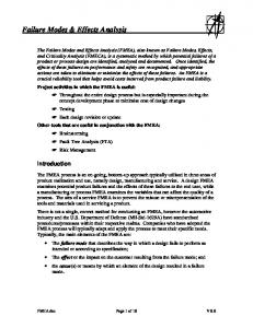
Figure 1: Map of Nepal showing district boundaries and the distribution of earthquake damaged buildings [1]. 1 Lecturer, Dept. of Civil and Environmental Engineering, The University of Auckland, Auckland, New Zealand,
[email protected] 2 Director, EQ STRUC Group, Auckland, New Zealand,
[email protected] 3 Professor, Dept. of Civil and Environmental Engineering, University of Canterbury, Christchurch, New Zealand
[email protected] 4 Technical Director, Miyamoto International (NZ) Limited, Christchurch, New Zealand,
[email protected] 5 Professor, Dept. of Civil and Environmental Engineering, The University of Auckland, Auckland, New Zealand,
[email protected] Chautara
212 approximately 4,500 km2 that included Kathmandu Valley. This earthquake severely damaged buildings in Kathmandu, and resulted in approximately 15,700 fatalities, including 8,519 fatalities in Nepal [9].
Figure 2: Main tectonic elements in the earthquake affected area [4] (where, from the south to north: MFT - Main Frontal Thrust, MBT - Main Boundary Thrust, MCT - Main Central Thrust).
Figure 4: Location and Mw magnitude of post 1934 Nepal earthquakes [13].
Figure 3: Nepal at junction of the Indian (southern) and the Eurasian (northern) tectonic plates [6]. History of Earthquakes in Nepal The United Nations has ranked Nepal as the 11th-most earthquake-prone country in the world [8]. Despite lying at a major plate boundary, large earthquakes on the Himalayan thrust are rare in the documented historical era although researchers claim that large earthquakes with a moment magnitude (Mw) of 7.5 or more did occur in Nepal in 1100, 1505, 1555, 1724, 1803, 1833 and 1897 in the preinstrumental historical period [4, 7-11]. A summary of major earthquakes felt in Kathmandu prior to 1934 is provided in Table 1. Table 1: Paleoseisms and historic earthquakes in and around Nepal (MMI greater than VII [7-12]). Magnitude (Mw)
In 1980 an earthquake of Mw 6.5 occurred in the western district of Bajhang in Nepal and caused 178 fatalities and damaged approximately 40,000 houses [10]. The 21 August 1988 earthquake of magnitude Mw 6.8 (different reports claim between Mw 6.5 and Mw 7.3) [12] was centred in Udaypur in eastern Nepal. The earthquake caused more than 1,000 fatalities (including some in Bihar, India), damaged an estimated 60,000 houses, and caused widespread damage to infrastructure. On 18 September 2011 an earthquake of Mw 6.9 was registered in the far-eastern part of Nepal (near the border with Sikkim, India) which reportedly [12] resulted in 8 fatalities, injured 150 people and damaged many traditional homes in the region. Earthquake-induced landslides further contributed to house and road damage. Earthquake induced ground shaking was felt as far as the Kathmandu Valley, where several houses sustained damage, and resulted in 3 fatalities from the collapse of boundary walls beside a busy road. More recently, an earthquake of Mw 6.0 occurred on 30 August 2013, followed by a Mw 5.0 aftershock a few minutes later. Shaking was felt in the Kathmandu Valley and in the central and western parts of Nepal, but no significant damage was reported.
Date
Information source
Intensity (MMI)
11000 BC
Seismite
≥XI
1100 AD
Trench
≥X
1255 AD
Historic and Trench
X
1408 AD
Historic and Trench
X
>8.5
1505 AD
Historic
≥VII
8.2-8.8
1681 AD
Historic
1767 AD
Historic
1810 AD
Historic
IX
1833 AD
Historic
IX-X
7.61
1833 AD
Historic
IX
~7
n/a – data not available
1833 AD
Historic
VIII
~7
1866 AD
Historic
VIII
7.6
1934 AD
Instrumental
X
>8.0
~8.5
Table 2: Summary of major earthquakes felt in Kathmandu post 1934. Date
Magnitude (Mw)
Approx number of damaged buildings
Fatalities
15 January 1934
>8.0
n/a
8519
IX
29 July 1980
6.5
40,000
200
≥VII
21 August 1988
6.8
60,000
1,091
18 September 2011
6.9
n/a
8
30 August 2013
6.0
n/a
0
MMI - Modified Mercalli Intensity Scale Mw - earthquake moment magnitude
As shown in Figure 4, a number of events of Mw 6 or larger have occurred in Nepal over the past century (also see Table 2). The last major earthquake in the region was the great Nepal-Bihar earthquake of 15 January 1934, which caused extensive loss of life and property. This was a mega earthquake with an Mw greater than 8. Modified Mercalli Intensity (MMI) up to X was recorded in an area of
2015 Gorkha Earthquake and Aftershocks The Mw 7.8 2015 Gorkha earthquake occurred at 11:56 NST on 25 April 2015 with a focal depth of approximately 1015 km and an epicentre located near Barpak village in Gorkha district, which is located 77 km (48 miles) northwest of the capital city Kathmandu [14], see Figure 5. The earthquake occurred on the Main Himalayan Thrust as a result of unlocking between the subducting Indian Plate and the overriding Eurasia Plate to the north, see Figure 2. The rupture propagated from west to east, thereby leading to more severe destruction in the eastern part of Nepal when compared to western Nepal [4].
213
CHINA
NEPAL
INDIA
damaged, including private and Government buildings (data recorded on 15 June 2015 [1]). Figure 1 shows the distribution of buildings that were damaged in different districts of Nepal, which are prevalently concentrated in the Gandaki, Bagmati and North of Janakpur Zones (highlighted in red and orange), located between Pokhara and Mt. Everest. However, the effects of the 2015 Gorkha earthquake were observed in many buildings throughout all parts of Nepal. Overall, millions of people were left homeless and the total direct financial loss exceeded $3.5 billion (USD) for the housing sector alone and $7.0 billion (USD) as a total direct loss [16]. A number of documents have been published pertaining to general observations following the 2015 Gorkha earthquake and aftershocks [17-18] and hence the information provided herein is presented in a brief summary form. Table 3: Causalities by country for the 2015 Gorkha earthquake [1].
Figure 5: Map depicting epicentres of more than 100 aftershocks that have occurred since the Mw 7.8 Gorkha earthquake in Nepal on 25 April 2015 [15]. The Gorkha earthquake was followed by hundreds of aftershocks on a daily basis. More than 390 aftershocks of Mw 4 or greater were recorded, 5 of which were greater than Mw 6. The largest aftershock was Mw 7.3 on 12 May 2015 (17 days after the first earthquake), which substantially added to the damage and number of casualties. Almost all aftershocks originated from east of the epicentre of the main earthquake, extending up to 130 km to the east of the first epicentre [14]. The location, frequency, magnitude and the trend of the aftershocks are plotted in Figure 2 and Figure 6. The majority of the aftershocks were at a relatively shallow depth of less than 20 km below the Earth's surface (see Figure 2).
Figure 6: Aftershock (above Mw 4) distance and magnitude [provided by Roger Bilham]. The 2015 Gorkha earthquake sequence was the most devastating disaster to strike Nepal since the earthquake in 1934. Of the 75 districts of Nepal, 31 districts in the Western and Central regions were affected by the earthquakes, including the three districts in the Kathmandu Valley [16]. Out of 31 affected districts, 14 were declared as ‘crisis-hit’ [16]. Most of the afflicted districts are densely populated, including remote villages located on steep topography. Widespread earthquake damage was also reported in neighbouring China, India and Bangladesh [1] (see Table 3). Following the 2015 Gorkha earthquake sequence 513,500 buildings were identify by the Nepal Government as fully damaged and 295,300 buildings were identified as partially
Country
Deaths
Injuries
Nepal
8,789
22,300
India
130
560
China
27
383
Bangladesh
4
200
Total
8,950
23,452
A set of ground motions from a recording station in Kathmandu was made available by U.S. Geological Survey (USGS). The displacement, velocity and acceleration timehistories recorded at the station along three directions are shown in Figure 7. It can be seen that N-S was the dominant shaking direction (although a comparable level of shaking took place in the E-W direction) and that the recorded peak ground displacement (PGD) and peak ground acceleration (PGA) were approximately 1.4 m and 0.16 g, respectively. The 5% damped acceleration response spectra of the two horizontal motions are plotted in Figure 8, together with the design spectra used in the Indian seismic design standard [19] for a site with comparable seismicity and with similar site conditions. It can be seen that the induced ground motions peak at periods 0.3 sec (N-S component) and 4.5 s (both N-S and E-W components) and exceeded the design demand for structures of all periods (except for stiff structures with a period less than 0.3 sec). The cause of the former is not clear to the authors at this stage, whereas the latter is caused by the combination of long-period content of seismic waves at source and site amplification due to the basin effects [18]. It should also be noted that the calculated design peak ground acceleration on the soft soil site in the Kathmandu Valley was estimated to be 0.36g [20] which is approximately double that of the recorded peak ground acceleration during the 25 April earthquake. Also, the induced demand was unusually high for structures with natural periods ranging between 4 and 6 seconds. Despite spatial variation of ground motions, the earthquake spectra illustrated in Figure 8 partially explains the significant damage that was observed in tall and flexible reinforced concrete (RC) frame structures in the Kathmandu Valley. The modification of the motion, whereby high frequency components were filtered and the low frequency components were amplified, can be attributed to the presence of soft clay deposits in the Kathmandu Valley basin (location of the accelerogram recording station). This filtering may have resulted in the slow, rolling motions experienced in the Kathmandu Valley, where the motions were characterised by a large displacement amplitude with less severe peak ground acceleration, with large acceleration response across periods above 0.3s.
214
Figure 7: Kanti Path, Kathmandu, Nepal (USGS Sta KATNP), Record of April 25, 2015 6:11:46.6 GMT (Filtering: Highpass at 02 Hz (50 sec) USGS Strong Motion Processing. Although the available data is limited, an attempt was made by Aydan and Ulusay [17] to investigate the attenuation of maximum ground accelerations. Figure 9 shows the attenuation of strong motion together with observed and inferred data from collapsed or toppled structures. The data is approximately consistent with available empirical relations proposed by various researchers [17]. It is evident that the recorded PGA at the Kantipath station in Kathmandu was less than the value given by most attenuation relationships for the corresponding magnitude and distance. Figure 8: Response Spectrum of recorded ground motion for the Mw 7.8 main shock and its comparison with Indian design spectrum [19].
LOADBEARING MASONRY BUILDINGS During inspection surveys several types of unreinforced masonry (URM) loadbearing structures were identified [21], including the following
Adobe masonry Stone masonry with mud mortar Stone masonry with cement-based mortars Raw or kiln fired clay brick masonry with mud mortar Kiln fired clay brick masonry with cement mortar
Many older URM buildings were poorly maintained and in a deteriorated condition, and the harsh climate with heavy monsoon rains had resulted in the growth of moss and vegetation on building surfaces. In some cases it appeared that building maintenance measures were not taken until the building was in a state of near collapse.
Figure 9: Comparison of empirical relations for attenuation of maximum ground acceleration with observed and inferred data [17]. Kantipath station is shown with a square.
Current NZSEE guidance for the seismic assessment of unreinforced masonry buildings [22] is primarily focussed towards comparatively simple clay brick unreinforced masonry buildings as is typically encountered on the main streets of provincial New Zealand towns or the village centres of larger New Zealand cities [23]. Recognising that New Zealand practitioners would benefit from additional guidance regarding how to address a wider scope of URM building types, the macro-element procedure developed in Italy [24] is introduced here as a method to illustrate the utility of the procedure and as a resource for future possible introduction of the method in New Zealand. The method was previously
215 applied to unreinforced masonry churches damaged in the Canterbury earthquakes [25]. Unreinforced Stone Masonry Buildings Unreinforced stone masonry was the most commonly occurring building type in the severely-affected rural areas, where this building type suffered a disproportionally high level of damage. Typically the walls of unreinforced stone masonry buildings are constructed of boulders, rubble stones, or dressed/semi-dressed stones using mud mortar or in some cases dry stacked masonry units. Floor diaphragms are commonly constructed using timber members overlaid with mud. The roof is usually constructed using lightweight corrugated iron sheets or slate tiles on timber framing (see Figure 10 and Figure 11). These buildings are commonly single or two storeys high with an attic storage space. Typically there is a lack of integrity between orthogonal walls, and between walls and floor/roof diaphragms. Stone masonry buildings are sometimes constructed using cement mortar, and may have RC floor and roof diagrams as shown in Figure 12.
Figure 11. Rocking and shear failures in stone masonry piers and spandrels were also observed in a number of cases (for example see Figure 11a,b and Figure 13a). Stone masonry buildings that were constructed using well integrated RC floor and roof diaphragms and good mortar (such that potential outof-plane mechanisms were mitigated) generally resulted in adequate performance with minimal observed damage (see Figure 12 for example).
Damage Mechanisms in Stone Masonry Buildings Wall delamination: Use of weak mud mortars and poorly integrated multi-leaf stone walls frequently led to delamination of wall cross-sections and potential collapse of buildings (see Figure 10).
(a) Stone masonry building in Chautara
(b) Stone masonry building in rural area
27° 46’ 38.48” N 85° 42’ 22.91” E
28° 12’ 31.84” N 84° 4’ 52.33” E
Figure 10: Examples of observed delamination of external stone leaf (provided latitude and longitude coordinates are in the WGS84 standard format).
(a) Traditional stone masonry building with in-plane and corner damage
(b) Stone masonry building in Chautara
(c) Typical wall crosssection and OOP damage (Chautara)
Figure 11: Corner damage to unreinforced stone masonry buildings.
Out-of-plane failure mechanisms: As expected for buildings with architectural features such as long span façades, flexible floor diaphragms, and weak connections between return walls, partial or complete overturning or instability of loadbearing walls was commonly observed, with damage ranging from moderate to severe and in many cases partial/full building collapse. Most buildings with out-of-plane failures appeared to have poor return wall connections, leading to return wall separation and subsequent out-of-plane failure of entire walls (see Figure 11). Connections between diaphragms and walls were non-existent in almost all observed buildings. In-plane failure mechanisms: Whilst most stone masonry building failures were attributed to out-of-plane mechanisms, a number of in-plane failure mechanisms were also observed. Stone masonry buildings with corner damage are shown in
Figure 12: Unreinforced stone masonry building with cement mortar and RC floor and roof diaphragms (minor to no damage observed).
216 that are involved in the brick manufacturing process observed in Kathmandu Valley.
(a) Out-of-plane collapse and in-plane failures both in the piers and spandrels
(a) Raw material
(b) Mud and hand moulded bricks
(c) Sun drying
(d) Stacking of ‘raw’ bricks in the kiln and isolation cover
(e) Fuel for firing chamber
(f) Air fan for enforced air movement
Unreinforced clay brick masonry is widely used in the construction of Nepalese buildings and was a commonly encountered form for loadbearing masonry construction. Commonly sun dried (adobe) or kiln fired bricks are used for building construction, with mud mortar joints.
(g) Removal 10-15 days after baking
(h) Finished brick product
Clay Brick Manufacturing in Nepal
Common Construction Practice and Building Typologies
Clay brick manufacturing activity is prevalent throughout Kathmandu Valley and is briefly reported herein in order to provide background to brick construction in Nepal. Variations of Hoffmann type kilns were observed, where the principle of regenerative heating is utilised. A Hoffmann kiln consists of several chambers that are connected together such that heat is transferred from one chamber to another until it has dissipated. Each chamber has an outer door, holes at the top for fuel insertion, and a small flue which is connected to the chimney flue to generate heat. The chambers are typically divided using intercepting dampers. Figure 14 illustrates the typical stages
Clay brick URM construction practice was widely variable between inspected buildings and Figure 15 to Figure 17 illustrate commonly observed details for the construction of walls and diaphragms. Mud mortar is typically sourced from or near a construction site and is manually mixed on-site using shovels, hands and feet. The quality of mud is highly depended on the location of extraction. In almost all observed cases the bricks were laid in an English bond pattern (see Figure 15). In some cases it was observed that ‘raw’ clay bricks (adobe, sun dried only) were used in construction in order to reduce material cost and better thermal properties. It
(b) Collapse due to poor quality of the masonry (Chautara)
(c) Damaged dry stacked stone masonry building Figure 13: Collapse of unreinforced stone masonry buildings with mud mortar or dry stacked masonry. Unreinforced Clay Brick Masonry Buildings
Figure 14: Clay brick manufacturing process.
217 is not uncommon for the buildings located in Kathmandu Valley, mostly in the older buildings, to be clad adobe walls with fired clay bricks used for the exterior leaf to protect adobe from weather and for aesthetic reasons. However, the cladding veneers are not tied to the main structural walls. The walls are usually 230 to 460 mm thick. However, palaces and monumental buildings have walls with larger thickness. It was observed that poor corner return wall interconnection is common.
(a) Mud mortar mixing onsite
topping (see Figure 23b). This type of building typology typically occurs in poorer residential areas and frequently consists of closely spaced standalone or row multi-storey buildings, as shown in Figure 17a. Typically, these buildings have a simple rectangular plan with a width of approximately 6 m and a length varying from 3 to 10 m. The foundation is usually a shallow type strip footing made using stones in mud mortar.
(b) Brick and mortar transportation (a) Bamboo floor diaphragms with a heavyweight mud topping (typical domestic URM construction)
(c) Masonry construction, using English bond pattern and fired clay bricks
(b) Timber floor diaphragm, in some cases with heavyweight brick and mud topping 27°40’51.54”N 85°19’6.54”E
(d) Masonry construction, using English bond pattern and ‘raw’ clay bricks (sun dried only) Figure 15: Commonly encountered construction of loadbearing unreinforced masonry walls. In residential multi-storey clay brick URM construction, flexible timber floors are present and at times were observed to be constructed of timber beams that were supplemented by bamboo canes positioned between the timber beams to reduce the cross-span dimension (see Figure 16). Smaller bamboo canes or split bamboo are used for planking, with a mud
(c) Jack arched heavyweight diaphragms, with thickness ranging up to 400 mm (16”) – mainly in Palace-type buildings 27°40’51.54”N 85°19’6.54”E
Figure 16: Typical diaphragms used in loadbearing URM buildings with no diaphragm-to-wall connections.
218
(a) Examples of standalone and row loadbearing URM buildings with mud mortar in poorer residential areas
(b) Example of residential URM buildings with cement mortar (c) Example of mid-range URM buildings with cement mortar and and RC floor and roof diaphragms RC floor and roof diaphragms
(d) Example of a typical Rana Palace with mud mortar
(e) Victorial style Palace in Kathmandu Durbar Square
27°40'14.26N 85°18’48.97E
Figure 17: Examples of typically occurring typologies for loadbearing clay brick unreinforced masonry buildings. Some newer commercial and mid-rise URM buildings in more affluent areas were observed to consist of well fired clay brick URM and cement-based mortar construction with RC floor and roof diaphragms, with examples of such building types shown in Figure 17b,c. In buildings of higher importance, such as palaces (traditional Nepali architecture and Victorian era architecture), regularly spaced timber joists are used with tongue and groove type flooring (see Figure 16b), similar to commonly observed diaphragm construction in New Zealand vintage URM buildings. The floor is then commonly overlaid with brick and/or mud topping. Wall-to-diaphragm connections were not observed for any of the URM building types. In some Palace type Victorian style URM buildings jack arched heavyweight floor and roof diaphragms with a thickness ranging up to 400 mm were identified. Such systems are commonly used for rooms of high importance where sound
and vibration isolations is important and in areas of high foottraffic, such as hallways (see Figure 16c). Examples of typical Palace type buildings are shown in Figure 17d,e. Damage Mechanisms in Clay Brick URM Buildings Out-of-plane failure mechanisms: Clay brick URM buildings were observed to commonly suffer damage due to deficient lateral capacity, lack of integrity between walls, and lack of connection between the walls and floor/roof diaphragms. Outof-plane wall collapse was the most commonly observed failure mode for clay brick URM buildings following the 25 April 2015 Gorkha earthquake, with many multi-storey buildings losing their entire front façades or upper storey walls. As seen in past earthquakes, for example the 1997 Umbria-Marche, Italy earthquake, the 2009 L’Aquila, Italy
219 earthquake [26-29] and the 2010/2011 Canterbury earthquake sequence [30-31], façade walls are amongst the most vulnerable elements of URM buildings and are often subjected to out-of-plane overturning mechanisms in the form of macroelements. The failure mode involving separation of the front façade and return walls was commonly observed due to poor interconnection of return walls, as can be seen in the multiple examples shown in Figure 18. Façade overturning in buildings where corner connections were adequate are shown in Figure 19. Out-of-plane wall failures due to roof diaphragm flexibility were also observed and are shown in Figure 19 and Figure 20. Schematics are provided to aid with visualisation of this type of failure mode. As observed in numerous other earthquakes, out-of-plane collapse of the gable end walls was widely observed throughout Kathmandu Valley (see Figure 21).
(a) Return wall separation
(b) Return wall separation
Overturning of the building plan protrusions was observed in some of the historic Palace type URM buildings (see Figure 22), similar to damage that was observed and categorised in Italian [27] and New Zealand [25] churches following recent earthquakes. Due to building plan irregularity the protrusions typically sustained more damage than the rest of the building, in some cases leading to full collapse of the building protrusions as shown in Figure 22b. Movement of the floor diaphragm relative to the loadbearing URM walls was commonly observed in all types of URM buildings, and in some cases permanent movement of the floor joists relative to the adjacent wall of up to 100 mm was recorded, as shown Figure 23a. In some cases movement of the floor diaphragm led to full collapse of the heavy brick and mud floor topping, as shown in Figure 23b. Dislodged heavy roof tiles (see Figure 23c) were commonly observed, and on close inspection these roof tiles were usually not secured to the supporting timber framing below.
(c) Wall collapse due to return wall separation
27°40’56.64”N 85°22’55.52”E
(d) Schematic of return wall separation [24]
Figure 18: Observed example of return wall separation and overturning of the façade.
(a) Precursor to partial overturning of the façade
(b) Schematic of façade partial overturning [24]
(c) Schematic of out-of-plane bending of the wall [24]
Figure 19: Example of initiation of overturning of façades where return wall separation occurred through wall penetrations adjacent to building corners.
220
(a) Out-of-plane wall failure
(b) Out-of-plane wall failure
(c) Schematic of out-of-plane failure [24]. Also see Figure 21c
Figure 20: Out-of-plane wall failure due to roof diaphragm flexibility and three-sided boundary condition.
(a) Gable and partial façade wall collapse
(b) Gable and partial façade wall collapse
(c) Schematic of gable and partial façade collapse [24]
Figure 21: Out-of-plane collapse of gable end walls.
(a) Partial overturning
(b) Collapse
27°40'42.38N 85°19'2.62E
27°40'47.88N 85°18'49.41E
Figure 22: Overturning of the building plan protrusions.
(c) Schematic of overturning [24]
221
(a) Pull out of the timber joints supporting floor diaphragm
(b) Floor collapse, also showing bricks and packed mud overlying floor joists
27°40’51.54”N 85°19’6.54”E
27°40'47.88N 85°18'49.41E
(d) Schematic of diaphragm movement [24]
(e) Schematic of floor collapse [24]
(c) Dislodged heavy roof tiles 27°40'47.88N 85°18'49.41E
(f) Schematic of dislodged heavy roof tiles [24]
Figure 23: Damage to floor and roof diaphragms. In-plane failure mechanisms: Other mechanisms that were frequently encountered in clay brick URM buildings in Nepal are associated with in-plane response of the structure. Damage occurring in the plane of URM walls was widely observed, including:
In-plane damage to arches Diagonal shear cracking in piers, spandrels and walls
Shear sliding on mortar bed joints or between storeys In-plane rocking and toe crushing of piers.
Significant in-plane damage to arches found in Victorian style Palace-type URM buildings was observed, as shown in Figure 24. In most cases the middle portion of the arch remained in place but appeared to be in a near-collapse state.
Diagonal shear cracking was observed in piers, spandrels and internal walls. Figure 25 shows shear cracking in internal walls and in piers respectively, while Figure 26 shows severe near-collapse shear failure of a clay brick external pier in a building with rigid RC floor diaphragms. In Figure 27, compression of piers and minor evidence of toe crashing is shown for a three storey URM building with RC floor and roof diaphragms. This particular building showed evidence of highly torsional response with pier compression failures occurring at the external corner piers. Several types of spandrel failure were observed, including flexural cracking, diagonal cracking and bed joints sliding, see Figure 28. Failure types depended on spandrel geometries, relative material properties, and boundary conditions.
(a) Significant damage to arch
(b) Significant damage to arch
27°41'24.54N 85°19'11.77E
27°41'24.54N 85°19'11.77E
Figure 24: In-plane damage to arches.
(d) Schematic of arch damage [24]
222
(b)
(c)
(a) Diagonal shear cracking observed in internal loadbearing walls (a) Loadbearing URM building with rigid RC diaphragms
(b) Schematic of diagonal shear cracking observed in internal loadbearing walls [24] Figure 25: Diagonal shear cracking in internal loadbearing walls.
(b) Compression damage of pier
(c) Signs of toe crushing at external building corner
Figure 27: Compression damage of corner piers.
(a) Flexural cracking
(a) Severe diagonal shear cracking of piers
(b) Diagonal cracking
(b) Schematic of diagonal shear cracking of piers [24] Figure 26: Diagonal shear cracking of piers.
(c) Bed joint sliding Figure 28: Observed in-plane spandrel damage types.
223 Pounding damage was observed in densely populated areas where rows of buildings with varying heights and lack of seismic separation gaps were located. Pounding induced lateral forces at the contact points that resulted in localised heavy in-plane damage of loadbearing URM piers, as shown in Figure 29, which led to a state of near collapse for many buildings [see 32].
(b)
(a) Pounding damage example
observed damage to temple towers in Bhaktapur Durbar Square are shown in Figure 30. Durbar squares, consisting of a combination of palaces, temples and courtyards surrounded by residential buildings which were originally constructed during the era of the old Malla Kings dating back to the 15th century. Nepalese Pagoda temples were constructed as structures reserved for religious or spiritual activities, and began to appear around the middle of the 14th century during the Malla Dynasty (1200–1768) [34]. These temples are constructed using clay brick masonry and timber members with tiles or metal roof coverings [36].
(b) Close-up of (a)
(a) Partial collapse of a small temple tower, with remaining buildings standing but with some damage
(c)
(c) Pounding damage example
(d) Close-up of (c)
(b) Partial collapse of temple tower exposing the wall cross-section and internal construction
(c) Partially collapsed redclay brick temple
Figure 30: Observed damage to temple towers at Bhaktapur Durbar Square.
(e) Schematic of pounding damage [24] Figure 29: Observed damage due to pounding.
Observed damage to temples and an example temple crosssection is shown in Figure 31 and Figure 32. Well dressed and dry stacked stone masonry temples with symmetrical and regular geometries performed well with relatively minor damage observed (see Figure 33).
MASONRY TEMPLES This section is intended to provide a brief overview of the observed damage types for cultural heritage sites in Kathmandu Valley. A database of selected cultural heritage sites in Kathmandu that were damaged during the Gorkha earthquake is presented in [33] and in other online sources. Nepal has eight cultural UNESCO World Heritage cultural sites, out of which seven are located in the Kathmandu Valley. The cultural heritage sites located in the Kathmandu Valley were severely damaged in the 1934 earthquake [9, 34] and subsequently rebuilt. Many of the temples in Kathmandu Valley that were destroyed or badly damaged by the 2015 earthquakes were located in the three main Squares: Kathmandu Durbar Square, Patan Durbar Square and Bhaktapur Durbar Square. Selective examples of
(a) Collapse of top portion of a Pagoda type temple Figure 31 continued next page
224 in Nepal over the last few decades, with most RCFMI buildings having been constructed in the last 30 to 40 years. Construction of RC shear wall buildings was rarely observed, although lift cores are at times constructed using RC structural walls. RCFMI buildings vary widely in height, with the most commonly occurring heights ranging between 2 and 6 storeys, but with several RCFMI apartment buildings that are over 20 storeys high.The roof and floor diaphragms of these buildings are typically cast in-situ RC slabs. The cladding and partition walls are usually constructed using concrete block, clay brick or stone masonry, with the use of clay bricks in cement mortar being the most common form for the construction of partition walls and external perimeter infill walls. (b) Leaning of top portion of a Pagoda type temple
(b) Cross-section showing foundation and wall thicknesses [35]
Figure 31: Observed damage to tall Pagoda type temples and example building cross-section.
(a) Damage to smaller Pagoda temples with temporary propping to reduce further damage during aftershocks
RCFMI buildings are usually designed (only in cases where they are engineered) as bare frame moment resisting frame buildings, and hence brick or block masonry infill is structurally not required but is typically installed as partitions or cladding within the frame, despite the fact that the deficient effects of these masonry infill walls are well documented. URM partition walls are usually one leaf (110 mm) thick and external URM infill walls are usually two leafs (230 mm) thick. Usually these infill walls are neither tied into the frame, nor reinforced, although in a small number of cases two 6 mm diameter bars are placed every fifth or sixth brick course. It is common practice to construct the RC frame first and lay the URM walls later (infill frame), although construction of walls first and framing elements later (referred to as confined masonry) is not uncommon for small buildings [37]. Due to irregular brick sizes and other imperfections in construction of walls and concrete elements, thick cement plaster of up to 40 mm in thickness was common observed. The unnecessary thick plaster layers hide any imperfections within structural elements and result in additional seismic weight of a building. Typical construction details for RC frame buildings with masonry infill are illustrated in Figure 34 and Figure 35.
(b) Cross-section showing foundation plinth and large wall thicknesses [35]
Figure 32: Observed damage to smaller Pagoda type temples and example building cross-section.
(a) Foundation pit with URM walls and RC column
(a) Minor damage in masonry temple
(b) Stones commonly used for foundations
(b) Minor damage in octagonal temple built in 1637-47
Figure 33: Minor damage observed to dry stacked granite stone temples in the Patan Durbar Square, Kathmandu Valley. RC FRAME BUILDINGS WITH MASONRY INFILL Cast in-situ RC moment-resisting framed buildings with masonry infill (hereafter referred to RCFMI buildings) are one of the most commonly encountered structural types in urban, and semi-urban areas of Nepal for office, residential, and institutional uses. This building typology has rapidly emerged
(c) Construction of foundation grid with RC ring beams and column reinforcing Figure 34 continued next page
225
(d) Construction of the reinforced concrete stringcourse
(a) Cantilever/overhanging floor levels resulting in severe elevation irregularity
(b) Slender building with split levels and no seismic separation gabs between buildings
Figure 36: Common adverse irregularity features of RCFMI buildings in the Kathmandu Valley. Although many RCFMI buildings with masonry infills suffered damage, well-conceived buildings performed remarkably well. The main deficient features of RCFMI buildings were:
(e) Typical diaphragm used in confined masonry buildings (showing type of formwork used) Figure 34: Typical construction of RCFMI buildings.
• • • • • • •
Adverse building geometrical features (Figure 36) Soft storey failure mechanisms (see Figure 37) Poor construction quality (see Figure 38) Settlement of foundations (see Figure 39) Out-of-plane and in-plane damage to masonry infills (see Figure 41 to Figure 42) Poor reinforcement detailing (see Figure 43) Location of building appendages (see Figure 45).
RCFMI buildings frequently suffered from configuration problems and from strength and ductility deficiencies. Column failure that led to partial or total building collapse was occasionally observed, and it was evident that the masonry infills in these buildings acted as diagonal compression struts with the RC beam and column frame members behaving as tie members, holding the masonry infill panel together rather than acting as a moment-resisting frame. The developed forces are transferred to the RC frames and introduce additional shear demands into the columns. In moment-resisting frames a strong beam-weak column hierarchy appeared to be common based on numerous observations of column hinging failures.
(a) Building during construction
(b) Completed building, typically left unplastered
Subsequent sections briefly describe observations made by the reconnaissance team during the post-earthquake surveying efforts. Multiple earthquake reconnaissance studies around the world [38-42] have previously reported observed damage pertaining to the performance of RCFMI buildings that are similar to the buildings observed in Nepal. Hence, the included information herein is brief and not intended to repeat what are well-known issues with this building type. Soft Storey Collapse Mechanisms A major problem with current Nepalese RCFMI buildings is the formation of a soft storey mechanism, particularly at (but not limited to) the ground storey. Typically the ground floor of such buildings functions as an open shop-front or similar, in order to satisfy the functional requirements of street-front or ground-level uses (without masonry infills), thereby reducing the stiffness and capacity when compared to the portions of the building containing masonry infills.
(c) Building finished with rendered plaster and paint
(d) Building clad with tiles and plaster
Figure 35: Typical RCFMI buildings.
226 integral part of seismic construction. Some of the commonly encountered detailing problems are insufficiently large spacing of ties in columns and beams, inadequate anchorage of reinforcement, improper bending of hooks, insufficient reinforcement in the beam-column connections, insufficient concrete cover, and improper splicing of reinforcement. Poor construction quality was widely observed during the postearthquake inspections, with some commonly encountered examples provided in Figure 38.
(a) Soft storey collapse example 1
(a) Poor quality concrete
(b) Insufficient lap splice length Thick rendering plaster layer
Insufficient lap splice
(b) Soft storey collapse example 2
Clay brick as aggregate Poorly tied and widely spaced Poor quality stirrups concrete (c) Column of a collapsed RC building Figure 38: Damage induced by poor quality of construction. (c) Soft storey collapse example 3
Damage due to Foundation Settlement In some parts of Kathmandu Valley widespread differential settlement of buildings was observed (see Figure 39). Many observed cases were related to poor ground performance under earthquake conditions and the use of non-engineered foundations.
>75 mm
>100 mm
(d) Pancake collapse Figure 37: Soft storey collapse examples. Damage Induced due to Poor Quality of Construction A major issue with current design and construction practice in Nepal is the detailing of RC members. The quantity and quality of the reinforcement used in these buildings is often inadequate and ductile design is still not considered as an
(a) Differential movement due to foundation rotation
(b) Vertical differential movement due to settlement
Figure 39: Observed damage due to foundation settlement.
227 Out-of-Plane and In-Plane Damage to Masonry Infills Out-of-plane and in-plane damage to masonry infills was widely observed, particularly in areas near the epicentre and in the Kathmandu Valley. See Figure 40 to Figure 42 for examples. In some observed cases where openings through masonry infills were located adjacent to a column, the partial-height infill restrained the portion of the column below the opening, resulting in short-column effects, in turn leading to a brittle shear mode of failure in columns instead of the ductile flexural failure mode that was intended (see Figure 41). In areas where strong ground shaking occurred (i.e. Chautara near aftershock epicentre), multiple cases of significant shear dilation of infill walls was observed which led to further damage to the gravity loadbearing columns (see Figure 42b-c).
Figure 40: Out-of-plane collapse of the infill masonry walls.
(a) Significant sliding along mortar joints and bed joint shear failures of infill masonry walls
(b) Significant shear dilation of infill walls leading to damage of gravity loadbearing columns
Shear failure of columns
(c) Severe shear dilation of infill walls leading to failure of gravity load supporting columns Figure 41: In-plane damage to masonry infills and significant shear failure of RC columns due to ‘shortcolumn’ effect. Staircases The staircases of RCFMI buildings were observed to typically be constructed integral with the RC frames. The stair landings were commonly supported by masonry walls or landing beams, which essentially create short columns when subjected to lateral loads (Figure 43).
Figure 42: Significant in-plane damage to infill masonry walls. Water Tank Supports Due to the scarcity of fresh water, the regulated supply of ground water, and the low pressure of the water supply system in the Kathmandu Valley, water storage tanks are typically placed on roofs of newer buildings. Examples of the most commonly encountered arrangements of water tank support systems are illustrated in Figure 44.
228
(a) Severe damage to loadbearing column in four storey building due to a staircase
(b) Column shear failure due to stairway landing connection at column mid-height
(a) Cantilevered RC support platform
(b) URM support platform
(c) Steel braced frame support frame
(d) Shear wall type of support platform
Figure 44: Commonly observed water tank support structures. Due to amplification effects up the building height and the slender heavy cantilevered mass atop of roofs, water tank supports suffered extensive and widespread severe damage, and in some cases collapsed (see Figure 45).
(c) Close-up of b, shear failure of columns
(a) Plastic hinging of cantilevered RC support columns (d) Damage due to a rigid staircase Figure 43: Damage to loadbearing columns due to presence of a staircase.
Figure 45 continued next page
(b) Flexural cracking of cantilevered support column
229
(c) Collapse of cantilevered RC support platform
(c) Visible damage and cracking (d) Typical multi-storey RC through plaster layer in masonry frame building with masonry infill walls, exposing RC frame infill Figure 46: Multi-storey RC frame with masonry infill residential and mall buildings. TEMPORARY SHORING
(d) Insufficient lap splice (close-up of c) Figure 45: Typical damage observed for cantilevered RC water tank supports (180 mm lap splice).
For URM buildings damaged in the 2015 Gorkha earthquake, simple temporary shoring was commonly used to stabilise buildings or building parts against collapse (see Figure 47 and Figure 48). When comparing these shoring examples with those used in the 2012 Pianura Emiliana (Italy) earthquake, the 2010-2011 Canterbury (New Zealand) earthquakes [31] or the 2009 L’Aquila (Italy) earthquake [39], it is evident that training that addresses the installation of temporary shoring in Nepal will allow for more robust and feasible implementations.
TALL BUILDINGS With increasing land cost and changes in living style, large multi-storey apartment and mall buildings have become common in Nepal in the last 10 years (see Figure 46). As with the mid-rise RCFMI building type, these buildings are usually designed as bare moment resisting frame buildings, and hence brick or block masonry infill is structurally not required but is typically installed as partitions or cladding within the frame. Infill walls remain popular because they provide better security, are durable and weather-tight, and are the most cost effective option. (a) Shoring of a cultural heritage monument
(a) Bare RC frame under construction with infills to be added later
Figure 46 continued next column
(b) Example of shoring using bamboo members
(b) Severe damage to lower floor infill walls in a multistorey RC frame residential building (c) Example of shoring using timber members Figure 47 continued next page
230
(a) Example of a splice detail with three nails per side in a timber brace
(b) Temporary propping of a near collapsing five storey residential URM building
(d) Example of shoring using timber members
(c) Example of propping against extreme bulging of a five storey building Figure 48: Examples temporary shoring of URM buildings. SUMMARY AND CONCLUSIONS
(e) An example of shoring using timber and steel members
A brief background on the 2015 Gorkha earthquake was provided and common construction practices that were identified during the reconnaissance team efforts were presented and briefly explained along with the observed earthquake damage. Emphasis was placed on URM building typologies and construction practices. Comparisons between URM building damage and published macro-element failure modes were provided using photographic and schematic examples. Commonly observed failure modes and potential causes of failure are also highlighted for buildings constructed of RC frames with masonry infills. Overall a wide range of construction types were observed. The three principal building typologies observed in the area impacted by the 2015 Gorkha earthquakes are: (1) Unreinforced stone masonry; (2) Unreinforced clay brick (including ‘raw’ sun dried bricks) masonry (URM); and (3) RC moment-resisting framed buildings with masonry infill (RCFMI). Unreinforced stone masonry was the most commonly occurring building type in the areas most severely affected by the 2015 Gorkha earthquake and aftershocks, particularly in rural regions where this type of building suffered a high level of damage. Wall delamination, out-of-plane failure mechanisms, and in-plane failure mechanisms were observed. Unreinforced clay brick masonry is widely used in the construction of Nepalese buildings and was a commonly encountered form for loadbearing masonry construction. This type of building suffered significant damage due to:
(f) Example of shoring along a narrow alleyway in Kathmandu Figure 47: Examples of temporary shoring and bracing of monuments and building of high heritage importance.
•
Clay brick URM was observed to commonly suffer damage due to deficient lateral capacity, lack of integrity between walls, and lack of connection between the walls and floor/roof diaphragms.
231 • • • • •
Out-of-plane wall collapse was the most commonly observed failure mode. Movement of floor diaphragms relative to the loadbearing URM walls was commonly observed in all types of URM buildings. Overturning of the building plan protrusions was observed in some of the historic Palace type URM buildings. The failure mode involving separation of the return walls was commonly observed due to poor interconnection of return walls. Out-of-plane wall failures due to roof diaphragm flexibility were also observed.
Many RCFMI buildings suffered damage, but well-conceived buildings performed well. The main deficient features of RCFMI buildings were: • • • • • • •
Hamish Nelson (AECOM, New Zealand) Rossella Nicolin (AECOM, United Kingdom) Bishal Subedi (Aurecon, New Zealand) In addition to team members and funding agencies mentioned above, the authors are also thankful to the staff at the Department of Urban Development and Building Construction (DUDBC), the Nepal Engineers Association (NEA) and the Institute of Engineering at Tribhuvan University of Nepal, as well as the Nepalese engineering teams who assisted in conducting damage assessments and post-earthquake evaluations of earthquake damaged building. REFERENCES 1
Adverse building geometrical aspects Soft storey failure mechanisms Poor construction practice and quality Settlement of foundations Out-of-plane and in-plane damage to masonry infills Poor reinforcement detailing Location of building appendages.
2
Overall, most of the observed issues pertaining to poor seismic performance of buildings could be markedly reduced over time by improving and increasing the level of education of the building design, construction, maintenance, and property owner/management sector.
4
3
5
ACKNOWLEDGMENTS The authors wish to acknowledge the efforts of the wider teams that were involved in the three separate trips to Nepal that formed the basis of the content reported herein. The financial and logistic support for the first trip was provided by the Ministry of Foreign Affairs and Trade (MFAT) and the team was led by Richard Sharp (BECA, New Zealand). The second trip was made possible by Global Fairness Initiative (http://www.globalfairness.org/) and the authors wish to thank the following team members: Homraj Acharya (Global Fairness Initiative, Nepal) David Biggs (Biggs Consulting Engineering, NY, USA) Benton Cook (WJE, Colorado, USA) Scott Douglas (Douglas Engineering, Washington, USA) Sonny Fite (Target, Minneapolis, USA) Mike Griffith (University of Adelaide, Australia) Charles Haynes (SDG-Structure, Tennessee, USA) Kelly Knowles (Martin/Martin Engineers, Colorado, USA) James Mwangi (Cal Poly State University, USA) Kenneth O'Nell (MHP, Los Angeles, USA) Peter Opsahl (Lund Opsahl, Washington, USA) Arturo Schultz (University of Minnesota, USA) George Stevenson (Structural Concepts INC, Tucson, USA) Shawn Stevenson (Morrison Hershfield, USA) Sabina Surana (Reid Middleton, USA) The third trip to Nepal was made possible by MFAT/New Zealand Agency for International Development (NZAID) via a contract awarded to AECOM and led by Steven Knowles to deploy a team to Nepal that involved all four of the authors. The authors wish to acknowledge the following team members: Mahendra Dixit (AECOM, New Zealand) Rori Green (AECOM, New Zealand) Paul Jacquin (LDE, New Zealand) Julian Maranan (AECOM, New Zealand) Abbas Mirfattah (Calibre Consulting, New Zealand) Bruce Mutton (Nelson City Council, New Zealand)
6
7
8
9
10
11 12 13
14
15
Statistics (2015). “Nepal Disaster Risk Reduction Portal, Government of Nepal”. www.drrportal.gov.np. (Accessed 15/06/2015). Saijo K, Kimora K, Dongol G, Komatsubara T and Yagi H (1995). “Active faults in south western Kathmandu basin, central Nepal”. Journal of Nepal Geological Society, 11 (Special Issue), 217-224. Nakata T and Kumahara Y (2002). “Active faulting across the Himalaya and its significance in the collision tectonics”. Active Fault Research, 22: 7–16. Sapkota SN, Bollinger L, Klinger Y, Tapponier P, Gaudemer Y and Tiwari D (2013). “Primary surface ruptures of the great Himalayan earthquakes in 1934 and 1255”. Nature Geoscience, 6: 71–76. Techtree (2015) “Why Himalayan Region is Prone to Earthquakes”. http://www.techtree.com/. (Accessed 22/11/2015). Washington Post (2015). “Nepal’s Earthquake: Mapping its Ripple Effect Across Asia”. https://www.washingtonpost.com/graphics/world/nepalearthquake/. (Accessed 22/11/2015). Srivastava1 HN, Bansal BK and Mithila Verma (2013). “Largest earthquake in Himalaya: An appraisal”. Journal Geological Society of India, 82:15-22. UNDP (2009). “Nepal Country Report-Global Assessment of Risk”. ISDR Global Assessment Report on Poverty and Disaster Risk 2009. United Nations Development Programme, Kathmandu, Nepal. www.undp.org.np/uploads/publication/201010290938349 9.pdf. (Accessed 22/11/2015). Rana BJ and Lall K (2013). “The Great Earthquake in Nepal (1934 A.D.)”. 1st English Edition. Kathmandu: Ratna Pustak Bhandar. ISBN 9789937330152. Bilham R (2004). “Earthquakes in India and the Himalaya: tectonics, geodesy and history”. Annals of Geophysics, 47(2): 839-858. Bilham R (2009). “The seismic future of cities”. Bulletin of Earthquake Engineering, 7: 839–887. Bilham R, Gaur VK and Molnar P (2001). “Himalayan seismic hazard”. Science, 293: 1442–1444. Ritzen Y (2015). Al Jazeera agency “Timeline: Nepal earthquakes”. http://www.aljazeera.com/indepth/ interactive/2015/04/timeline-nepal-earthquakes150425115801610.html. (Accessed 22/11/2015). National Seismological Centre (2015). “Nepal Earthquake”. Department of Mines and Geology, Government of Nepal, http://www.seismonepal.gov.np. (Accessed 22/11/2015). USGS (2015). “Map of Nepal Earthquake and Aftershocks”. United States Geological Survey. http://www.usgs.gov. (Accessed 15/06/2015).
232 16 NPC (2015). “Nepal Earthquake 2015: Post-Disaster Needs Assessment, Volume A: Key Findings Kathmandu”. Nepal Planning Commission, Government of Nepal. http://www.npc.gov.np/. (Accessed 22/11/2015). 17 Aydan O and Ulusay R (2015). “A Quick Report on The 2015 Gorkha (Nepal) Earthquake and its GeoEngineering Aspects”. International Association for Engineering Geology and the Environment (IAEG), 26pp. 18 Goda K, Kiyota T, Pokhrel RM, Chiaro G, Katagiri T, Sharma K and Wilkinson S (2015). "The 2015 Gorkha Nepal Earthquake: Insights from Earthquake Damage Survey". Frontiers in Built Environment, 1. 19 Indian Standards (2002). “IS-1893: Criteria for Earthquake Resistant Design of Structures, Part 1, General Provisions and Building”. Fifth Revision. Earthquake Engineering Sectional Committee, CED. 20 NBCDP (1994). “Seismic Hazard Mapping and Risk Assessment for Nepal”. (UNDP Pro# Nep.88.054-21.03), Nepal Building Code Development Project Nepal, His Majesty‘s Government of Nepal, Ministry of Housing and Physical Planning, UNCHS Kathmandu, Nepal. 21 Bothara J and Brzev S (2011). “A Tutorial: Improving the Seismic Performance of Stone Masonry Buildings”. First Edition, Earthquake Engineering Research Institute, Oakland, California. 22 NZSEE (2015). “Assessment and Improvement of the Structural Performance of Buildings in Earthquakes Section 10 Revision. Seismic Assessment of Unreinforced Masonry Buildings”. New Zealand Society for Earthquake Engineering, Wellington. 23 Russell AP and Ingham JM (2010). "Prevalence of New Zealand's unreinforced masonry buildings". Bulletin of the New Zealand Society for Earthquake Engineering, 43(3): 182-201. 24 DPCM (2006). “Approvazione dei modelli per il rilevamento dei danni a seguito di eventi calamitosi, ai beni appartenenti al patrimonio culturale – scheda “Chiese” e scheda “Palazzi.””. Ministry for Cultural Heritage and Activities, Italy. G.U. n.55 del 07-03-2006[In Italian]. 25 Leite J, Lourenco PB and Ingham JM (2013). “Statistical Assessment of Damage to Churches Affected by the 20102011 Canterbury (New Zealand) Earthquake Sequence”. Journal of Earthquake Engineering, 17(1): 73-97. 26 Lagomarsino S and Podestà S (2004). "Seismic Vulnerability of Ancient Churches: I. Damage Assessment and Emergency Planning". Earthquake Spectra 20(2): 377-394. 27 Lagomarsino S. (2009). “Damage assessment of churches after L’Aquila earthquake (2009)”. Bulletin of Earthquake Engineering, 10: 73-92. 28 Carocci C (2011). “Small centres damaged by 2009 L’Aquila earthquake: on site analysis of historical masonry aggregates”. Bulletin of Earthquake Engineering, 10: 45-71 29 D’Ayala D and Paganoni S (2011). “Assessment and analysis of damage in L’Aquila historic city centre after the 6th April 2009”. Bulletin of Earthquake Engineering, 9: 81-104 30 Dizhur D, Ismail N, Knox C, Lumantarna R and Ingham JM (2010). "Performance of Unreinforced and Reinforced Masonry Buildings during the 2010 Darfield Earthquake". Bulletin of the New Zealand Society for Earthquake Engineering, 43(4): 321-339.
31 Dizhur D, Ingham JM, Moon L, Griffith M, Schultz A, Senaldi I, Magenes, G, Dickie J, Lissel S, Centeno J, Ventura C, Leite J and Lourenco P (2011). "Performance of Masonry Buildings and Churches in the 22 February 2011 Christchurch Earthquake". Bulletin of the New Zealand Society for Earthquake Engineering, 44(4): 279296. 32 Cole GL, Dhakal RP and Turner FM (2012). "Building pounding damage observed in the 2011 Christchurch earthquake". Earthquake Engineering and Structural Dynamics, 41(5): 893-913. 33 Government of Nepal (2015). “Nepal Earthquake 2015: Disaster Relief and Recovery Information Platform”. Nepal Disaster Risk Reduction Portal, http://drrportal.gov.np (Accessed 24/11/2015). 34 Ranjitkar RK (2000). “Seismic Strengthening of the Nepalese Pagoda: Progress report. Earthquake-Safe: Lessons to be learned from Traditional Construction”. International Conference on the Seismic Performance of Traditional Buildings, Istanbul, Turkey, Nov. 16– 8, 2000. 35 Shakya M, Varum H, Vicente R and Costa A (2013). "Seismic sensitivity analysis of the common structural components of Nepalese Pagoda temples". Bulletin of Earthquake Engineering, 12(4): 1679-1703. 36 Parajuli YK, Amatya S and Sturzbecher K (1986). “Experience in preservation and restoration in a mediaeval town (1974-1985)”. Bhaktapur Development Project, Nepal. 37 Marhatta YB, Bothara JK, Magar MB and Chapagain G (2007). World Housing Encyclopaedia. “Housing Report: Pillar walaghar, URM infilled RC frame buildings”. http://www.world-housing.net/WHEReports/ wh100163.pdf. (Accessed 22/11/2015). 38 Bothara J K and Hiçyılmaz K (2008). “General Observations of the Building Behaviour during the 8 th October 2005 Pakistan Earthquake”. Bulletin of the New Zealand Society for Earthquake Engineering, 41(4). 39 Oyarzo-Vera C and Griffith MC (2009). “The Mw 6.3 Abruzzo (Italy) Earthquake of April 6th, 2009: On Site Observations”. Bulletin of the New Zealand Society for Earthquake Engineering, 42(4): 302-306. 40 Bothara J, Beetham R, Brunsdon D, Stannard M, Brown R, Hyland C, Lewis W, Miller S, Sanders R and Sulistio Y (2010). “General Observations of Effects of the 30 September 2009 Padang Earthquake, Indonesia”. Bulletin of the New Zealand Society for Earthquake Engineering, 43(3): p143-173. 41 Astroza M, Moroni O, Brzev S and Tanner J. (2012). "Seismic Performance of Engineered Masonry Buildings in the 2010 Maule Earthquake". Earthquake Spectra, 28(S1): S385-S406. 42 Hermanns L, Fraile A, Alarcón E and Álvarez R (2013). "Performance of buildings with masonry infill walls during the 2011 Lorca earthquake". Bulletin of Earthquake Engineering, 12(5): 1977-1997.