focusing the reflected light on a surface of a position sensitive detector (PSD). ... However, there have been quite a few attempts to automate mobile heavy.
BULLDOZER TRACKING AND NAVIGATION USING SERVO-CONTROLLED LASER RANGE FINDING TECHNIQUE Sakari Pieska*, Anssi Makynen+, Juha Kostamovaara +, Martti Elsila*, Risto Myllyla* *Technical Research Centre of Finland +University of Oulu Department of Electrical Engineering Electronics Laboratory Linnanmaa, SF-90570 Oulu Box 200, SF-90571 Oulu Finland
Finland
ABSTRACT Most of the positioning and navigation systems developed for construction machines have been focused on satisfying 2D navigation requirements. In this paper, a system is proposed for continuous and accurate tracking of a bulldozer or corresponding moving machine. Tracking is based on 3D coordinate determination using a time -of-flight laser range finder and angle encoders as a measuring head and optical reflectors attached to the machine. Tracking is accomplished by illuminating the cooperative target with an infrared emitting diode (IRED) or laser diode and focusing the reflected light on a surface of a position sensitive detector (PSD). Preliminary tests of the technique have been performed in a bulldozer's real working environment at a cellulose mill and have been promising : an angle resolution of about 200 Arad is achievable in a measurement range of up to 100 - 150 in using a spherical target constructed of highly reflective tape attached to the machine and a cw laser diode (8 mW) as the transmitter. 1. INTRODUCTION Heavy construction equipment play an important role in current civil engineering. However, there have been quite a few attempts to automate mobile heavy construction machines and most examinations have concentrated on machines moving on a plane /1, 2, 3/. Bulldozers are an example of widely used construction machinery which could benefit from a proper 3D positioning and navigation method by increased work efficiency, reduced labour costs and increased work safety. The development of a reliable positioning system is difficult because bulldozers are typically used in severe, unstructured and dynamic environments. One possible solution to the positioning and navigation problems of heavy construction machines is to develop an optical sensor for continuous tracking of the target and measurement of the distance from it. This kind of sensor could be installed on the moving machine to follow special marks on the edges of its working area. An alternative way is to use the sensor as a stationary servo-controlled measuring head to continuously track a retroreflector installed on the machine and thus determine its 3D coordinates. Laser-based tracking systems have been examined for many military and space applications where high accuracy and fast measurements are required /1, 4, 5/. A servo-controlled laser range finding system , where tracking is based on the use of a four-quadrant position sensitive detector can be developed to give good accuracy with moderate costs. The following chapters describe this type of tracking and navigation method, examine its possibilities as a navigation sensor of a moving construction machine and present the experimental measurement results gathered in the real working environment of a bulldozer.
379
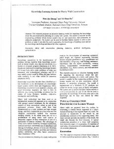
2. THE TRACKING AND NAVIGATION METHOD Principle of the Measuring Method The measurement system consists of a servo-controlled measuring head and reflectors. The two principal ways to use servo-controlled laser range finding as a tracking sensor are presented in Fig. 1. The measuring head can be located stationarily on the working site and the reflector is attached to the moving machine. If the measuring head is attached to the machine then the reflectors located at the working site can be considered as external reference points for the positioning system.
Fig.1. The alternative ways to install the servo-controlled measuring head. A block diagram of the measurement system is shown in Fig. 2. The measuring head consists of angle encoders and a pulsed time-of-flight laser range finder for measuring the 3D coordinates of the target. Tracking is accomplished by illuminating the reflector on the target with a laser diode or an IRED and focusing the reflected light on the surface of a position-sensitive detector acting as a null detector. The signals from the PSD are used as a feedback to drive the servomotors of the measuring head. Both the light emitter and the PSD are located in the measuring head.
COOPERATIVE TARGET
3D COORDINATES
Fig.2. The tracking and navigation system diagram. Distance Measurement The distance between the reflector and the sensor can be determined by a time-offlight (TOF) laser range finder. Short laser pulses are emitted towards an object with a high frequency (1 kHz - 1 MHz). The distance is obtained from the time-interval between the transmitted and the reflected light. The typical pulse rise time and width are 2 ns and 10 ns respectively. The receiver consists of an avalanche photodiode (APD) connected to the input of a transimpedance preamplifier, postamplifiers, a gain control unit and a timing discriminator.
380
Gain control is necessary for several reasons: the optical power received depeiids on the measurement distance and the reflectivity of the object and atmospheric conditions also influence measurements. Gain control can be accomplished either electrically, e.g. by controlling the operating voltage of the APD by means of PIN diode attenuators, or mechanically, e.g. by using a variable neutral density attenuator in front of the receiver. The laser diode transmitter and receiver are usually connected to the optics of the system by fibers, which enables one to obtain a more homogeneous light beam and maintain easy control over the divergences of the receiver and transmitter. Angle Measurements The angle measurements (azimuth and elevation) of the sensor can be accomplished with optical angle encoders. Typical resolutions for incremental sensors vary from 10 to 100 Arad which means an approximately 1 - 10 cm resolution in positioning at a measurement range of 1 km. The accuracy of an incremental sensor is +/- 50 - 250 prad which leads to a 5 - 25 cm accuracy at a 1 km distance. Tracking Target tracking is based on the use of a position sensitive detector (PSD) as a null detector for servo control of the measurement head. As a transmitter, either an IRED or laser diode can be used and the cooperative target can be e.g. a corner cube or a sphere covered with a reflective tape. The reflected light is focused on the surface of a PSD with a positive lens, see Fig. 3. Q_ d [rod) f
POSITIVE LENS A
P5D
Fig. 3. A position sensitive detector as a null detector in tracking. The x and y coordinates of the reflected light spot are calculated from the four current signals of the detector. The position sensitive detector can be a lateral effect photodiode or a four-quadrant detector as in Fig, 4. (iA+iB) - (iC+iD)
X= iA+iB+iC+iD (iA+iD) - (iB+iC)
Y = iA+iB+iC+iD
1A' iB, iC and iD are the average currents of the diodes A,B,C and D
Fig. 4. A four-quadrant position sensitive detector.
381
A four-quadrant detector can be considered as a simple form of an array detector having four separate photodiodes positioned symmetrically around the axis of the sensor. When the image spot of the target is located on the optical axis of the receiver, the output signal of each photodiode is equal, thus producing no error signal. As the spot moves across the detector the x and y positions of the spot can be determined as presented in Fig. 4. A more detailed description of the tracking method, together with distance and angle measurements can be found in /6/. 3. SUITABILITY OF THE METHOD TO CONSTRUCTION The employment of automatic construction machines or construction robots sets some new requirements for measurements. Table 1 presents a summary of the most essential measuring requirements of construction robotics which were analyzed in a study carried out lately in the Technical Research Centre of Finland /7/.
Table 1. The most essential measurement needs for construction robotics.
PROBLEMS
NEW SOLUTIONS
On/off sensors Limit switches
Information restricted
Smart sensors and multisensor systems
Indirect measurements from actuators
Information restricted Slowness
ROBOT
Dead reckoning
POSITIONING
(based on inter-
AND NAVIGATION
nal sensors)
Inaccuracy, Error accumulation
MEASUREMENT
CURRENT
NEEDS
METHODS
MEASUREMENTS FOR THE MOTION CONTROL
Path following
Difficult to use during construction
sensors
Combinations of internal and external sensors (3D positioning)
Problems related
2D measurements based on external
to reliability, accuracy and quick
reference points
system set-up ENVIRONMENT
Tactile sensors
Information
SENSING
Ultrasonic or optical sensors for obstacle
restricted and inaccurate
detection
382
Machine vision or laser scanner based multisensing systems
The proposed servo-controlled laser range finding method could be a solution for the central measuring task, positioning and navigation, and the same base-technology (laser range finding) can also be used for environment sensing as a form of laser scanner /8/. In addition, a laser-based 3D pointer can be utilized in the man-machine interaction, including environment modelling, task description and path teaching / 9, 10/. The accuracy and speed of the proposed servo-controlled laser range finding are sufficient for most positioning tasks in construction. A reliable navigation system can be achieved using some simple internal sensor, such as an odometer, to assure reliable operation also in unexpected situations, e.g. when there is temporarily no sight between the sensor and the target. The use of a stationary measuring head on the working site and retroreflector on the machine would be the most probable solution for outdoor positioning tasks of heavy construction machines such as levelling bulldozers, press rollers and earth augers. In many indoor navigation tasks, it would be reasonable to attach the measuring head to the moving machine and determine the 3D coordinates by using external reference points, e.g. corner cubes. The advantages achieved through the use of a four-quadrant position sensitive detector in tracking are high speed, resolution accuracy and stability together with a cheap price and simplicity of realization. The well-known advantages of the distance measurement by the TOF technique are good resolution, short measurement time and a wide measurement range /1, 6/. By current TOF-technique measurement a resolution of 1 mm and an accuracy of +/- 3 mm is achievable in a measurement range of several hundred meters, with appropriate targets. This accuracy is quite sufficient for most of the positioning and navigation applications of construction. 4. EXPERIMENTAL RESULTS ON BULLDOZER TRACKING Earlier experimental work has included some basic measurements to examine the achievable tracking resolution as a function of signal level, measurement range and the construction of cooperative target /6/. That experimental system consisted of an IRED and laser diode transmitter, a four-quadrant detector with associated electronics, coaxial optics and two types of cooperative targets. The main focus of the work has been on utilization of the PSD technique for tracking purposes.The achievable measurement range and tracking resolution were measured in both indoor and outdoor conditions. The angle resolution was measured to be 200 Arad in a measurement range of 120 m in laboratory conditions. In field conditions, air turbulance effects can lower the resolution. The spherical target seems to be more tolerant to these atmospheric effects than a corner cube. The other observed advantages of a spherical target were its large field-of-view and accurate definition of the target centre point.
Table 2 presents the outdoors measurement data of tracking resolution obtained by two kinds of transmitters and two kinds of cooperative targets . The transmitters were a 0.7 mW IRED transmitter and a cw laser diode (8 mW) and the cooperative targets were a corner cube retroreflector with an aperture of 25 mm and divergence of 150 }grad and a sphere with 15 cm diameter covered with highly reflective tape. The results in Table 2 indicate that the tracking resolution achieved using a reflective sphere is better than with a corner cube when equal signal levels are given.
383
Table 2. Tracking resolution as a function of the input power of a receiver. Range 40 rn, outdoors
Target: EU,, angle res . (prad) Target: corner 3.5 348 reflective cube 1.7 410 sphere 0.9 332 0.4 298 0.2 314 0.1 342 0.05 256
Range 40 m, outdoors angle res. (jirad) 26 3.5 26 1.7 0.9 28 0.4 28 0.2 30 46 0.1 72 0.05
Experimental bulldozer tracking measurements were carried out at a cellulose mill in varying environmental conditions including many kinds of air impurities (e.g. dust, rain , fog). The outdoor tracking tests were carried out in both winter and summer conditions ; Fig. 5 presents some photos of the outdoor measurement arrangements. In these preliminary tests a stationary measuring head continuously tracked a bulldozer with a reflective sphere on the top of the machine. The servo head consisted of a transmitter, a receiver , a helium-neon pointer and the servo motors with associated electronics. Target tracking was accomplished with the four -quadrant position sensitive detector described previously.
a)
b)
c)
Fig. 5 . Measurement arrangements used on bulldozer tracking: a ) the servo-controlled measuring head, b) bulldozer working, c) the reflective sphere. The results from the experimental tracking measurements indicated that the sensor was able to track the bulldozer up to 140 m when the transmitter was a 8 mW laser diode and the cooperative target was a sphere covered with reflective tape (see Fig. 5). When an IRED was used as a transmitter and a corner cube as a retroreflector, the maximum tracking range was about 95m. In addition to tracking tests, the effects of environmental conditions on TOF-based distance measurement were examined on the working field of a bulldozer . Rain, snow and dust did not have any effect on the reliability of the distance measurement. The only temporary troubles were encountered with heavy fog.
384
Fig. 6 presents the first step of proposed system development for bulldozer tracking at a cellulose mill where the bulldozer's task is to transfers piles of wood chips. The first step in the planned automation process is the operator assisted system presented in Fig. 6. The most remarkable safety risk on the piles of wood chips is that a bulldozer or an operator who has got out of the machine can fall into the discharger situated under the field. The discharger area is often covered with wood chips and therefore is difficult to recognize. The second step in that application could be an unmanned remote control system which includes blade elevation control. TRACKERI OPTICAL OR RADIO COMMUNICATION
TRACKER 2
MICRO CONTROLLER AND MONITOR REFLECTIVE (MAP WITH LOCATION DATA) SPHERE \
OPTICAL OR RADIO COMMUNICATION
ODOMETER
Fig. 6. An operator assisted system for a bulldozer at a cellulose mill. 5. CONCLUSIONS An optical sensor is presented for tracking and navigation of heavy construction machines such as bulldozers. Tracking and navigation is based on the combination of time-of-flight laser range finding and position sensitive detection technique. The method seems to be suitable for many positioning and navigation tasks in construction. Some experimental results are presented concerning tracking resolution as a function of measurement range, signal level, transmitter type and the construction of the cooperative target. The tracking method has been demonstrated at a cellulose mill, where the sensor was able to track a spherical target attached to the top of a bulldozer up to 150 m. The next steps in this research will include the development of an optical and electrical construction for combining the laser range finder and the tracking system, an evaluation of achievable tracking accuracy and a more thorough study of the effect of air turbulance and noise induced by background radiation. The feasibilty of the method for the positioning and navigation of heavy earthwork machinery and an interior finishing robot is also planned to be examined in future projects.
385
ACKNOWLEDGEMENTS The authors wish to thank Dr. Raimo Ahola, Noptel Ky, Mr. Iikka Autio, Veitsiluoto Oy, Dr. Markku Manninen, Prometrics Oy, and Mr. Aulis Ryhanen, Occupational Safety District of Oulu, for their contribution to this work. The experimental part of this research was financed by the Finnish Work Environment Fund. REFERENCES 1 Goodin , A.C., Boyer, L. T., Identification and measurement technologies applicable to construction. Proc . of the 4th Int. Symp. on Robotics and Artificial Intelligence in Building Construction, Haifa, Israel, 1987 , pp. 863 877. 2 Ochi, T., Mio, K., A positioning system for mobile robots in construction applications ("Laser Positioner"). Proc. of the 5th Int. Symp. on Robotics in Construction, Tokyo, Japan, 1988, pp. 333 - 340. 3 Sato, K, Hisatake, T., Unmanned system for a heavy construction equipment. Proc. of the 5th Int. Symp. on Robotics in Construction, Tokyo, Japan, 1988, pp. 449 - 458. 4 Clowes, T.J., Schuma, D.F., Target Acquisition and Track in the Laser Docking Sensor. Proc. of SPIE, Vol. 931 Sensor Fusion, 4-6 April 1988, Orlando, Florida, pp. 143 - 148. 5 Johnson, R.E., Optical engineering of first- and second-generation automatic tracking/laser designator pods. Optical Engineering 18(1979)4, pp. 370 - 375. 6 Kostamovaara, J., Makynen, A., Myllyla, R., Method for industrial robot tracking and navigation based on time-of-flight laser rangefinding and position sensitive detection technique, SPIE , Hamburg , 1988, 8 p. 7 Pieska, S., Lindholm, M., Measurement requirements and advanced techniques for construction robotization. VTT Research notes, Technical Research Centre of Finland, 1989, (to be published). 8 Moring, I. et al., Acquisition and processing of range data using laser-scanner based 3-D vision system. Proc of the SPIE Conference on Optics, Illumination and Image Sensing for Machine Vision, Cambridge, MA, USA, November 1987, 10 p. 9 Makynen, A., Kostamovaara, J., Myllyla, R., A laser-based 3D sensor for teaching robot paths. Proc. of SPIE, Vol. 954 Optical Engineering and Industrial Sensing for Advanced Manufacturing Technologies, 23-30 June 1988, Dearborn, Michigan, 8 p. 10 Pieska, S., Elsila, M., Vaha, P., Laser pointer based task-level control for heavy duty machines. 3rd IFAC Conference on Man-Machine Systems (3rd MMS), 14 - 16 June 1988, Oulu, Finland, pp. 467 - 471.
386