Int J Adv Manuf Technol DOI 10.1007/s00170-016-8747-5
ORIGINAL ARTICLE
Burr height minimization using the response surface methodology in milling of PH 13-8 Mo stainless steel Luiz Carlos da Silva 1 & Paulo Rosa da Mota 1 & Márcio Bacci da Silva 2 & Wisley Falco Sales 2 & Álisson Rocha Machado 2,3 & Mark James Jackson 4
Received: 2 February 2016 / Accepted: 4 April 2016 # Springer-Verlag London 2016
Abstract Burrs formed during the machining process is considered a major problem in the manufacturing industry because they can impair mechanical assemblies, change the dimensions of the machined products, and compromise the physical integrity of the operators, among many other inconveniences. Therefore, burrs should be avoided but if formed their dimensions should be minimized. In this work, the burr dimensions were investigated, and the cutting conditions that minimize them were determined using a central composite design (CCD) and response surface methodology (RSM) in face milling of PH 13-8 Mo stainless steel with coated carbide inserts. Burr formed on the workpiece exit edge and the behaviors of its height during the manipulation of the evaluated variables (tool exit angle from the workpiece, cutting speed, feed per tooth, axial depth of cut and average tool flank wear) were analyzed. The burrs were indirectly measured, where replicas of the workpiece edges (with their burrs) were produced with condensed silicone. The results showed that there is a considerable reduction in the burr height when lower exit angles and new cutting tools are used. The minimum number
* Wisley Falco Sales
[email protected]
1
Federal Institute of Education, Science and Technology of Goiás, Av. Assis Chateaubriand, 1658, Setor Oeste, CEP: 74130-012 Goiânia, GO, Brazil
2
Faculty of Mechanical Engineering, Federal University of Uberlândia, Av. João Naves de Avila, 2121, CEP: 38400-902 Uberlandia, MG, Brazil
3
Mechanical Engineering Graduate Program, Pontifícia Universidade Católica do Paraná—PUC-PR, CEP 80215-901 Curitiba, PR, Brazil
4
Kansas State University, 2310 Centennial Road, Salina, Kansas, KS 67401, USA
of burrs is produced when using increasing feed per tooth and decreasing axial depth of cut. The cutting speed presented negligible influence on the height of the burr. Keywords Burr height . PH 13-8 Mo stainless steel . Milling process . Response surface methodology (RSM)
1 Introduction As undesirable residue of machining, burrs are usually formed during the manufacturing processes. The ISO 13715 [1] standard defines burr as the “remaining material found outside the nominal geometric shape of an outer edge of a component, left as residue in the machining or forming process.” Burrs compromise the quality of the parts, as they are responsible for geometric distortion and dimensional changes, typically disturb the assembly of mechanical systems, thereafter raising the cost of manufactured products [2, 3]. In production lines with robots, burrs will disturb the handling of parts from one workstation to another, since the references found by the robot when the gripper holds the workpiece are out of those described in the program and as a consequence there may be stoppage in the manufacturing production line, promoting great loss of time and therefore increasing costs of production. In addition, the burrs may pose risks to the physical integrity of the professionals who handle the pieces during the various stages of manufacturing [2, 3]. Depending on the several drawbacks, it becomes necessary to make the removal of the burrs, and this new operation is designated by “deburring.” The deburring is normally a manual operation made by an employee, removing burrs from each piece, one by one, hence making the process slow and costly. In automated lines, however, the deburring is done by robots that direct water jets under high pressure and flow to
Int J Adv Manuf Technol
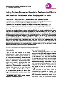
Fig. 1 Identification of the burr height (h) and thickness (tb)
the regions in which they occur. At the same time, these jets clean the workpiece. However, these central stations for deburring, depending on its complexity can be very costly and sometimes impractical. Therefore, the study of the phenomenon of burr formation is valuable because favorable conditions can be suggested and applied for reduction of its dimensions or even elimination [4–7]. The burr can be dimensionally characterized by its height (h) and the root thickness (tb), as shown in Fig. 1. The quantification of these dimensions requires special measuring systems, since measurement using instruments with contact sensors should not be used, because they promote the geometric deformation of the burr and thus shows false output signal for dimensions. Measuring systems with proximity sensors (contactless) are best suited. In the production lines, the burr length, h, is ease to be measured and then, usually is the most widely used in the shop floor; however, the thickness of the burr, tb, is the most important parameter since it is linked to the breaking difficulty of the burr. A burr can be long but thin, that makes it break easily. Burrs can be formed in any machining processes such as turning, milling, drilling, reaming, grinding, sawing, among others, involving severe plastic deformation. The burrs in milling processes are formed at the edges of the pieces obtained from the peripheral or face milling operations, and they have been investigated by Gillespie [3]. In Fig. 2a, b, c, several kinds of burrs are shown on the borders of the milled surfaces. This identification has considerable importance in the analysis of the mechanisms of formation of burrs.
Fig. 2 Classification of burrs formed by the process: a face milling, b discordant tangential milling, and c end milling [2]
Due to the importance of the process, several classification of burrs formed during milling were proposed [8]. The burr classification based on the type of workpiece edge and cutting tool edge was presented by Hashimura et al. [9]. According to them, one of the main factors that determine the burrs classification is the relative location between the tool edge and the boundaries of the workpiece. Depending on this position, the burr can assume some of these types, as output, side, and top burrs. Cutting conditions applied to the face milling have magnitudes that are always connected to the formation of burrs. The combination of factors such as cutting speed, feed rate, depth of cut, geometry between the workpiece/tool in addition with tool wear may determine the size and morphology of burrs. The effects of these parameters on the formation of burrs may appear alone or in combination [9–13]. The behavior of the tool exit angle from the workpiece (Ψ) was investigated by Olvera and Barrow [4] when machining AISI 1040 steel and by Da Silva [14] when machining GH 190 gray cast iron. They noted a great dependence of the burr dimensions in relation to this exit angle (Ψ)—this angle depends on the relative position between the workpiece and the milling cutter and consequently on the radial depth of cut, as illustrated in Fig. 3. During the milling of aluminum alloy AlSi7Mg, Avila and Dornfeld [10] found larger burrs with high radial depth of cuts in comparison to cases where the radial depth of cuts is smaller. In their work, the variation of the radial depth of cut was provided by changes in the tool exit angle from the workpiece (Ψ) or vice-versa. The wear of the cutting tool is considered another variable of major importance in the study of burr size, as found by Sales and Souza Jr [5] and by Da Silva [14, 15]. In these studies, the burr size always increased when the tool wear increased, during face milling of GH 190 gray cast iron and PH 13-8 Mo stainless steel. It is intended with this work to contribute further to the study of the burr formation on face milling of PH 13-8 Mo stainless steel, a material that has many applications in the aircraft components such as landing gear and structural sections, valves, shafts, and several components for the petrochemical and nuclear industries; furthermore, it is relatively difficult to be machined. In a previous work [16], the influence of the main cutting parameters (cutting fluid application method
Int J Adv Manuf Technol
2 Experimental procedure
Fig. 3 Top view of the milling process showing the tool exit angle from the workpiece (Ψ)
(flooding, low flow, MQL and dry), cutting tool geometry and radial depth of cut) on burr dimensions were studied in face milling of PH 13-8 Mo stainless steel. It was found that the burr is considerably influenced by the cutting tool geometry and radial depth of cut, but not by the method of application of the cutting fluid. In a second paper [17] using the same work material, emphasis was given to the transition from primary-to-secondary burr and the influence of deburring between passes in face milling. It was shown that the transition from primary-tosecondary burr depends considerably on the radial and axial depths of cut and the remnant burr (if deburring operation is not carried out between passes) dimensions increases linearly with the number of passes. In the present work the burr dimensions were investigated, and the cutting conditions that minimize them were determined using a central composite design (CCD) and response surface methodology (RSM) in face milling of PH 13-8 Mo stainless steel with coated carbide inserts.
Table 1 Input variables with their respective levels
Input
vc (m/min) fz (mm/tooth) ap (mm) VBB (mm) Ψ (o)
The main objective of the present work is to determine the cutting conditions that minimize the burr dimensions and a central composite design—CCD was used to accomplish this goal. Burrs formed during face milling of the PH 13-8 Mo hardened steel were experimentally evaluated. After machining, the burrs formed at the exit edge of the workpiece (identified as number 9 in Fig. 2a) had their dimensions measured. The average flank wear (VBB), the tool exit angle from the workpiece (Ψ), the depth of cut (ap), the feed per tooth (fz), and the cutting speed (vc) were the input variables studied, and the levels of them are presented in Table 1. The reduced influence of the cutting fluid in the size of the burr, verified previously [16], suggested the investigation of dry tests. Deburring between passes was always carried out in order to remove the remaining burrs, as they have considerable influence at the size of burr under study [17]. Response surface methodology (RSM) was used, after obtaining the data from the experiments following the central composite design, which was divided in three stages. In the first, full factorial design—FFD (25) resulted in 32 trials. In the next stage, tests with axial points (2k, where k = 5) resulted in ten more tests, followed by three tests at the central point (n2), totalling 45 experimental trials. Table 2 shows the contrast planning matrix. The levels of independent variables are coded as +α, +1, 0, −1, and −α, and the value of α is 1.7244. A test and three replicas were performed randomly for each trial, totalling 180 tests (45 + 3 × 45 = 180). This procedure allowed estimating the experimental error, and the residue was given by the analysis of variance. 2.1 Work materials, experimental apparatus, and tooling The work material used was the PH 13-8 Mo (AISI S13800), a martensitic stainless steel hardened by precipitation, solution annealed and aged, with an average hardness is 44 HRC. Table 3 shows its chemical composition, and Fig. 4 shows its microstructure, consisting of aged martensite with molybdenum carbide precipitates and less than 5 % of retained austenite as well as some oxides inclusions.
Levels Lower point (−α)
Basic down (−1)
Average (0)
Basic upper (+1)
Upper point (+α)
70 0.04 0.35 0.02 47°
85 0.06 0.50 0.10 67°
105 0.08 0.70 0.20 94.5°
125 0.10 0.90 0.30 122°
140 0.12 1.04 0.38 141°
Int J Adv Manuf Technol Table 2 Table 1
Contrast planning matrix proposed with the levels shown in
Test number
Independent variables VBB
Ψ
ap
fz
vc
1
−1
−1
−1
−1
−1
2
−1
−1
−1
−1
+1
3 4
−1 −1
−1 −1
−1 −1
+1 +1
−1 +1
5 6
−1 −1
−1 −1
+1 +1
−1 −1
−1 +1
7
−1
−1
+1
+1
−1
8 9
−1 −1
−1 +1
+1 −1
+1 −1
+1 −1
10
−1
+1
−1
−1
+1
11 12
−1 −1
+1 +1
−1 −1
+1 +1
−1 +1
13 14 15 16
−1 −1 −1 −1
+1 +1 +1 +1
+1 +1 +1 +1
−1 −1 +1 +1
−1 +1 −1 +1
17 18 19
+1 +1 +1
−1 −1 −1
−1 −1 −1
−1 −1 +1
−1 +1 −1
20 21 22
+1 +1 +1
−1 −1 −1
−1 +1 +1
+1 −1 −1
+1 −1 +1
23 24 25
+1 +1 +1
−1 −1 +1
+1 +1 −1
+1 +1 −1
−1 +1 −1
26 27
+1 +1
+1 +1
−1 −1
−1 +1
+1 −1
28 29 30 31 32 33 34 35 36 37
+1 +1 +1 +1 +1 −α +α 0 0 0
+1 +1 +1 +1 +1 0 0 −α +α 0
−1 +1 +1 +1 +1 0 0 0 0 −α
+1 −1 −1 +1 +1 0 0 0 0 0
+1 −1 +1 −1 +1 0 0 0 0 0
38 39 40 41 42 43 44 45
0 0 0 0 0 0 0 0
0 0 0 0 0 0 0 0
+α 0 0 0 0 0 0 0
0 −α +α 0 0 0 0 0
0 0 0 −α +α 0 0 0
The samples used in the tests had been previously designed and machined to provide five different exit angles (Ψ), according to the values presented on Table 1. These samples were inspired by the work developed by Avila and Dornfeld [10] and they are shown in Fig. 5. The sample 1 (Fig. 5a), with dimensions of 106 × 106 × 42 mm, with a groove previously prepared measuring 16-mm large was used for the tests 1 to 32. The sample 2 (Fig. 5b), with dimensions of 106 × 106 × 59 mm, with two grooves previously prepared measuring 10-mm large each was used for the tests 33 to 45. Machining experiments were carried out in a PETRUS 50100R CNC milling machine with 9.3 kW of power and maximum spindle speed of 8000 rpm. An Olympus BX51M digital optical microscope was used to measure the burr dimensions. Its XYZ displacement capacities are 100 × 50 × 115 mm3, respectively, with amplification up to 1000×. The microscope was equipped with a PM-20 CCD camera also manufactured by Olympus, and captured pictures were analyzed using Image-Pro Plus software. The milling cutter used was the 490-063Q22-08 L, with 63-mm diameter and five inserts capability, manufactured by Sandvik Coromant. The inserts are PVD coated (TiAlN-TiN) cemented carbide with the designation 490R-08T308M-MM 2030 (P20-40) also manufactured by Sandvik Coromant. 2.2 System for burrs measurement By means of an indirect system, the heights of the burr formed at the sample exit edges were measured. The burrs were molded using condensed silicone producing replicas (“negatives” of the burrs) that after being cut into thin layers allowed their dimensions be measured with the image analyzer software. Figure 6 illustrates the sequence of this process. In each exit edge of the workpiece (for each test of Table 2), three replicas of the burrs were produced in different points of the edge (according to Fig. 6) and in each replica two measures of the burr height were performed, totalling six measures for each exit edge. A test and three replicas in each condition of Table 2 were carried out; thus, a total of 24 measurements of the burr height in each condition were produced.
3 Results and discussion The burr height values for the 45 tests (according to Table 2, considering the replicas and two points of burr height measurement in each) are shown in Fig. 7. With the support of computational tools, the CCD could be solved fast and reliably. The Statistica 7.0 software was used to obtain the values of the main effects and interactions, according to previously established confidence intervals and the standard error thereof. Statistical results are shown in Table 4, and the parameters with significant influence on the burr
Int J Adv Manuf Technol Table 3 Composition of the stainless steel PH 13-8 Mo (AISI S13800)
Composition (wt. %) C
Si
Mn
P
S
Cr
Ni
Mo
Fe
≤0.045
≤0.10
≤0.10
≤0.01
≤ 0.002
12.25 to 12.90
8.00 to 8.50
2.00 to 2.50
Balance
dimension are identified in bold, considering 95 % of reliability (p value