The task of business object and rule modelling results in a conceptual model expressed in ..... procedures that denote execution semantics of transactions. ..... The definition of these metaclasses is self explanatory if the metamodels of figure 9 ...
Business Rules Modelling: Conceptual Modelling and Object-Oriented Specifications P. Loucopoulos, B. Theodoulidis, D. Pantazis Information Systems Group Department of Computation UMIST P.O. Box 88 Manchester M60 1QD
Abstract This paper argues that substantial benefits can be accrued from the explicit modelling of business rules and the alignment of the business knowledge to an information system. To this end, the paper introduces a conceptual modelling language for the capturing and representation of business rules incorporating aspects such as time modelling and complex objects. Together with the need for expressiveness power of conceptual modelling formalisms, this paper argues that one of the major challenges in the task of explicitly representing business rules is the ability of the chosen paradigm to provide facilities for clarification and consistency checking of the captured knowledge. The paper proposes the mapping of the externally (user-oriented) representation of business rules onto an Object-Oriented executable specification. This has the effect that validating the captured rules can be facilitated through the use of three levels of abstraction namely, model meta-knowledge, application knowledge and extensional knowledge.
1.
Introduction
In recent years there has been an increasing demand for information systems that provide a closer alignment between business policy and system operation c.f. [Fjeldstad et al, 1979; Balzer et al , 1983; Mathur, 1987; van Assche et al, 1988; Loucopoulos, 1989]. One of the central arguments in support of such an approach is that the evolution of information systems is, to a large extent, due to changes in the business environment and therefore, substantial improvements can be made in the development and evolution of systems if the business knowledge is explicitly captured and represented. This implies that organisational policy must be separated from the procedure which supports that policy and so allow a greater distinction between the ‘what’ and the ‘how’ aspects of a system (thus conforming to the preliminary report by ISO [van Griethuysen et al, 1982]). The requirement for modelling business rules is addressed by the TEMPORA1 project 1
The TEMPORA project has been partly funded by the Commission of the European Communities under the ESPRIT R&D programme. The TEMPORA project is a collaborative project between: BIM, Belgium; Hitec, Greece; Imperial College, UK; LPA, UK; SINTEF, Norway; SISU, Sweden; University of Liege, Belgium and UMIST, UK. SISU is sponsored by the National Swedish Board for Technical Development (STU), ERICSSON and Swedish Telecomm.
[Theodoulidis et al, 1990a; Loucopoulos et al, 1990] which provides the framework for the work reported in this paper. The term business rule is used in this paper to refer to ‘an explicit statement of a constraint expressed in the Conceptual Rule Language (CRL) - that exists within a business ontology as detailed by the Entity-Relationship-Time (ERT) model. The ERT provides the usual abstraction facilities of a binary relationship model (including classification and generalisation) and in addition it offers facilities for the modelling and reasoning of time and complex objects. The need for modelling time explicitly is that, for many applications when an information item becomes outdated, it need not be forgotten. The lack of temporal support raises serious problems in many cases. For example, conventional systems cannot support historical queries about past status, let alone trend analysis which is essential for applications such as Decision Support Systems. Research interest in the time modelling area has increased dramatically over the past decade as shown by published bibliographies [McKenzie, 1986] and comparative studies [Theodoulidis & Loucopoulos, 1991]. The need to accommodate complex objects [Adiba, 1987] arises from the fact that many applications have to deal with the modelling and management of objects of arbitrary complexity and to reason about them either in ‘whole’ or in a ‘decomposed’ form. The majority of current research efforts in this area deal with extensions to the relational model and include new types of attributes [Haskin, 1982] and the relaxation of the first normal form constraint [Abiteboul et al, 1989]. In both cases modelling of complex objects is carried out from a machine rather than a user-oriented perspective. Together with the need for expressiveness power of conceptual modelling formalisms, this paper argues that one of the major challenges in the task of explicitly representing business rules is the ability of the chosen paradigm to provide facilities for clarification and consistency checking of the captured knowledge. To this end, the paper proposes the mapping of the externally (user-oriented) representation of business rules onto an ObjectOriented executable specification. This has the effect that validating the captured rules can be facilitated through the use of three levels of abstraction namely, model meta-knowledge, application knowledge and extensional knowledge. The process of applying the capturing, modelling and validating techniques proposed in this paper is shown in the diagram of figure 1.
OBJECT & RULE MODELLING
Informal Requirements
Conceptual Model (ERT + CRL)
MAPPING Conceptual Metamodel (PROBE metaclasses) O-O Representation (PROBE classes)
SCHEMA CONSISTENCY CHECKING
Interpretation of intent
VALIDATION
Test data (PROBE instances)
Figure 1: Conceptual Modelling and validation The task of business object and rule modelling results in a conceptual model expressed in ERT and CRL, the details of which are given in section 2. A conceptual metamodel has been developed which has been used to create metaclasses at the PROBE level and which assists in the mapping of a domain-specific conceptual model onto the PROBE class level and in the consistency checking of the business knowledge. Section 3 discusses the conceptual metamodel and the mapping from external specifications to PROBE executable specifications. Finally, validation is carried out by using the PROBE run-time environment (this is discussed in section 4). 2.
Business Object and Rule Modelling
2.1
The Entity-Relationship-Time Model
2.1.1
Basic Concepts and Externals
The orientation of the ERT model is the Entity-Relationship formalism which makes a clear distinction between objects and relationships. On this basis, the ERT model offers a number of features which are considered to be necessary for the modelling of contemporary information systems applications. Specifically, it accommodates the explicit modelling of time, taxonomic hierarchies and complex objects. The different aspects of abstraction that can be used in the ERT model are classification, generalisation, aggregation and grouping. The most primitive concept in ERT is that of a class which is defined as a collection of individual objects that have common properties i.e., that are of the same type. In an ERT schema only classes of objects are specified (entity classes and value classes). In addition, every relationship is viewed as a named set of two (entity or value, role) pairs where each role expresses the way that a specific entity or value is involved in a relationship. These two
named roles are called relationship involvements and by using relationship involvements one has the possibility to express each relationship with two, syntactically different but semantically equivalent, sentences. Time is introduced in ERT as a distinguished class called time period class. More specifically, each time varying simple entity class or complex entity class and each time varying relationship class is timestamped with a time period class. That is, a time period is assigned to every time varying piece of information that exists in an ERT schema. The term time varying refers to pieces of information that the modeller wants to keep track of their evolution i.e. to keep their history and consequently, to be able to reason about them. For example, for each simple entity class or complex entity class, a time period might be associated which represents the period of time during which an entity is modelled. This is referred to as the existence period of an entity. The same argument applies also to relationships i.e., each time varying relationship might be associated with a time period which represents the period during which the relationship is valid. This is referred to as the validity period of a relationship. Besides the objects for which history is kept, another type of object, called event is also supported. These are objects that prevail for only one time unit and thus, the notion of history does not apply to them. Alternatively, one can say that these objects become history as soon as they occur. Events are denoted by defining the duration of their timestamp to be one time unit. As a consequence of the adopted timestamping semantics, only the event time is modelled in ERT; i.e. the time that a particular piece of information models reality. At a first glance this might seem to be restrictive in the sense that the captured information is not semantically as rich. However, this assumption is considered to be necessary in order to keep the proposed approach manageable and to permit computational attractive algorithms for reasoning about time. For each timestamp its granularity should be defined. The granularities however, should be carefully chosen as they affect the relative ordering of events stored in the database. For example, if DATE is the granularity of the SHIPMENT object, then two shipments received on the same date will be treated to have occurred at the same time even if their exact time of arrival differs. Another distinguished class that is introduced in ERT is that of a complex object. The distinction between simple and complex objects is that simple objects are irreducible in the sense they cannot be decomposed into other objects and thus, they are capable of independent existence whereas a complex object is composed of two or more objects and thus, its
existence might depend on the existence of its component objects. The relationship between a complex object and its component objects is modelled through the use of the IS_PART_OF relationship. The ERT model accommodates explicitly generalisation/specialisation hierarchies. This is done through a distinguished ISA relationship which has the usual set theoretic semantics. Furthermore, for each relationship involvement, a user supplied constraint rule must be defined which restricts the number of times an entity or value can participate in this involvement. This constraint is called cardinality constraint and it is applied to the instances of this relationship involvement by restricting its population. Each of the simple entity classes and user defined relationship classes in an ERT schema can be specified as derived. This implies that its instances are not stored by default but they can be obtained dynamically i.e. when needed, using the derivation rules. For each such derivable component, there is exactly one corresponding derivation rule which defines the members of this entity class or the instances of this relationship class at any time. In addition, if the derivable component is not timestamped then the corresponding derivation rule instantiates this component at all times whereas if this component is time varying then the corresponding derivation rule obtains instances of this class together with its existence period or validity period. In figure 2 an example ERT schema is given.
RegNo
Name
(1,1)
of
of
(1,1)
Salary
T
of (1,1)
(1,N) has
TOP SELLING PRODUCT
Dept.Name
of (1,1)
CAR
T
Price
T
(1,1)
of (1,1) has
of has (1-N) T
has (1,1)
(1,1)
EMPLOYEE
(1,1) T
works_for
T
has (1,1)
(1-N) employs
T DEPARTMENT develops
(1-N)
has (1,1) developed_by PRODUCT (1,1) best_ sold_by selling_ (0,N) product
has (1,1) MANAGER
T
T
T
(1,1)
has (1,1) of T
(1,N) ADDRESS of
(1,N)
of (1,1)
T
Office No. T
buys (1,N) (1,1)
CUSTOMER
T
has
best_ sales_ person
(1,1)
SALESPERSON
Figure 2: An example ERT schema As shown in this schema, entity classes e.g., EMPLOYEE are represented using rectangles with the addition of a 'time box' when they are time varying. Derived entity classes e.g., TOP_SELLING_PRODUCT, are represented as dashed rectangles. Value classes e.g., Name are also represented with rectangles but with a small black triangle at the bottom right corner to distinguish them from entity classes. Complex entity classes e.g., CAR and complex value classes e.g., ADDRESS are represented using double rectangles. Relationship classes are represented using a small filled rectangle (e.g. the relationship class between MANAGER and CAR), whereas derived relationship classes are represented using a non filled dashed rectangle (e.g the relationship between PRODUCT and SALESPERSON). In addition, relationship involvements and cardinality constraints are specified for each relationship class. The interpretation of these is for example “a MANAGER has one CAR and a CAR belongs to only one MANAGER” (the diagram shows minimum and maximum relationship involvements). The notation of the ISA hierarchies e.g., MANAGER ISA EMPLOYEE is also given in
figure 2. A distinction is made between different variations of ISA hierarchies. These are based on two constraints that are usually included in any ISA semantics namely, the partial/total ISA constraint and the disjoint/overlapping ISA constraint. It is assumed of course, that these constraints are applicable to hierarchies under the same specialisation criterion. These constraints are defined as follows: •
The partial ISA constraint states that there are members in the parent or generalised entity class that do not belong in any of its entity subclasses. On the other hand, the total ISA constraint states that there no members in the parent or generalised entity class that do not belong in any of its entity subclasses.
•
The overlapping ISA constraint states that the subclasses of a given parent class under the same specialisation criterion are allowed to have common entities whereas the disjoint ISA constraint states that the subclasses of a given parent class under the same specialisation criterion are not allowed to have common entities.
The first of these constraints refers to the relationship between the parent class or generalised class and the child class(es) or specialised class(es). The second constraint refers to the relationship between child classes. Based on the above constraints the four kinds of ISA relationships are supported namely, Partial Disjoint ISA, Total Disjoint ISA, Partial Overlapping ISA and Total Overlapping ISA. 2.1.2
Time Semantics
In the approach described in this paper, time is introduced as a distinguished entity class. For example, each entity class can be timestamped in order to indicate that its history is of importance to the particular application. The same argument applies also to user defined relationship classes and IS_PART_OF relationships. The ‘time periods’ approach was chosen as the most primitive temporal notion because it satisfies the following requirements [Villain, 1982; Ladkin, 1987]: •
Period representation allows for imprecision and uncertainty of information. For example, modelling that the activity of eating precedes the activity of drinking coffee can be easily represented with the temporal relation before between the two validity periods [Allen, 1983]. If one tries, however, to model this requirement by using the line of dates then a number of problems will arise since the exact start and ending times of the two activities are not known.
•
Period representation allows one to vary the grain of reasoning. For example, one can at the same time reason about turtle movements in days and main memory access times in nanoseconds.
The formal framework employed as the temporal reasoning mechanism is that of Interval Calculus proposed in [Allen, 1983] and which was later refined in [Loki, 1986] but with the addition of a formal calendar system in order to provide for the modelling and reasoning about the usual calendar periods. In figure 3, the semantics of the adopted time model is defined using ERT notation.
starts τ (0,N)
Time Period
(0,1)
(0,N)
(0,1)
(0,N)
τι (0,N) (0,1)
has_duration
(1,1)
finishes
(0,N)
NoOfTicks
Tick has
(1,1)
Calendar Period
Symbol Period
TickNo
Figure 3: The Time Metamodel The modelling of information using time periods takes place as follows. First, each time varying object (entity or relationship) of ERT is assigned an instance of the built-in class SymbolPeriod. Instances of this class are system-generated unique identifiers of time periods e.g. SP1, SP2, etc. Members of this class can relate to each other by one of the thirteen temporal relations between periods [Allen, 1983]. Instances of the SymbolPeriod class may be displayed in an ERT schema. If they are not included then a simple T in the time box indicates that the corresponding object is timevarying. The two subclasses of the Time Period class are disjoint as indicated in figure 7. This is because symbol periods are used to model relative time information while calendar periods model absolute time information. Thus, both views are accommodated. In figure 3, the symbol τ represents a temporal relationship and the symbol τι its inverse. In addition, time periods start and end on a tick and also have a duration expressed in ticks. A tick is defined as smallest unit of time that is permitted to be referenced and it is usually the time unit second. The CalendarPeriod class has as instances all the conventional Gregorian calendar periods e.g., 10/3/1989, 21/6/1963, etc. Members of this class are also related to each other and to members of the Symbol Period class with one or more of the time period comparison predicates. The temporal relationships between calendar periods follow a formal calendar system [Theodoulidis, 1990b] which is based on the work reported by Clifford and Rao in [Clifford & Rao, 1988] with the addition of the calendar unit 'week'. This was considered to
be necessary since there is often reference to this unit depending on the particular application domain. Any desirable calendar time unit can be defined as a combination of already defined calendar units. Thus, expressions like END_OF_MONTH and NEXT_FORTNIGHT are easily defined. The usual operators are provided including set operators and comparators. These are distinguished to those that are applied to elements of the same domain and those that are applied to elements of different domains [Clifford & Rao, 1988]. Additional operators like the time period comparison predicates are also provided together with functions that transform elements of one domain onto another. Note however, that the reasoning always takes place at the lower level of the ones involved. Other notions of time such as duration and periodic time are also represented directly in the proposed formalism in addition to the above specified ones. As a consequence, the expressive power of the proposed formalism is increased and so does its usability. These notions of time are expressed in the Conceptual Rule Language as constraints upon the structural components and also as constraints on the behaviour of procedures. The definition of the duration class is shown in figure 4. Members of this class are simple durations expressed in any abstraction level. Each duration consists of an amount of calendar time units expressed using real numbers and it is uniquely identified by the combination of its amount and abstraction level. For example, the duration '1,5 year' is a valid duration according to this definition.
Duration 1-1
in_units_of
0-N
Calendar Unit
1-1
has_amount
0-N
Real
Figure 4: Metamodel of the duration class The periodic time class is defined in figure 5.
Periodic Time has_base
from has_duration
Calendar Period
to
Calendar Period
Duration
Figure 5: Metamodel of the periodic time class As seen in this figure, a periodic time has a base which is a calendar period, a duration and also it can be restricted by a two calendar periods which restrict the set of values for this periodic time. For example, the expression 'first week of each month during next year' is a valid definition of a periodic time according to the above definition. In this case the calendar period corresponds to "1-7 days", the duration corresponds to "1 month" and the restricting calendar period is the next year corresponding to [1/1/1991, 31/12/1991]. A periodic time is uniquely identified by the combination of its base and its duration. 2.1.3
Complex Object Semantics
The basic motivation for the inclusion of the complex entity class and complex value class is from a methodological perspective, i.e. providing a designer with the ability to abstract away detail which in a particular situation is of no interest. No distinction is made between aggregation and grouping but rather a general composition mechanism for complex objects is introduced which also involves relationship classes. Graphically, composition is shown by surrounding the components with a rectangle representing the composite object class. The notation of a complex object in ERT is shown in figure 6. The complex entity class CAR and the complex value class ADDRESS of figure 2 may be viewed at a more detailed level as shown in figures 6 and figure 7 respectively. ADDRESS HasComponent
HasComponent 1-1
1-N
STREET NAME
1-N
CITY NAME
IsPartOf
1-1 IsPartOf
Figure 6: The complex value class ADDRESS in more detail The components of a complex object comprise one or more hierarchically arranged substructures. Each directly subordinate component entity class is part_of-related to the complex entity class border so that the relationship between the composite object and its
components will be completely defined. Whether the HasComponent involvement is one of aggregation or grouping, it can be shown by means of the normal cardinality constraints. That is, if its cardinality is (0,1) or (1,1), the component is aggregate whereas if its cardinality is (0,N) or (1,N), the component is a set. Most conceptual modelling formalisms which include complex objects [Kim et al, 1987; Lorie & Plouffe, 1983; Rabitti et al, 1988], model only physical part hierarchies i.e, hierarchies in which an object cannot be part of more than one object at the same time. In the ERT model, this notion is extended in order to be able to model also logical part hierarchies where the same component can be part of more than one complex object. To achieve this, four different kinds of IS_PART_OF relationships are defined according to two constraints, namely the dependency and exclusiveness constraints. The dependency constraint states that when a complex object ceases to exist, all its components also cease to exist (dependent composite reference) and the exclusiveness constraint states that a component object can be part of at most one complex object (exclusive composite reference). That is, the following kinds of IS_PART_OF variations [Kim et al, 1989] are accommodated: •
dependent exclusive composite reference
•
independent exclusive composite reference
•
dependent shared composite reference
•
independent shared composite reference
Note that no specific notation is introduced for these constraints. Their interpretation comes from the cardinality constraints of the IS_PART_OF relationship. That is, assume that the cardinality of the IS_PART_OF relationship is (α,β). Then, α=0 implies non dependency, α≠0 implies dependency, β=1 implies exclusivity while β≠1 implies shareness. CAR 1-1
HasComponent IsPartOf
1-1
DOOR
2- 4
HasComponent IsPartOf
1-1
MOTOR
1-1
has 1-1
of 1-N
of 1-N
Power
Color
has
Figure 7: The complex entity class CAR in more detail Complex object classes and IS_PART_OF relationship classes can be timevarying as shown in the above examples. This is discussed in detail later where the interaction of complex objects with time is elaborated. In particular, the way complex object hierarchies evolve over time and a number of constraints should always be valid during this process. 2.2
The Conceptual Rule Language
The CRL language is concerned with constraints placed upon the elements of ERT, with the derivation of new information based on existing information and with the invocation of procedures that denote execution semantics of transactions. Within the CRL formalism, different rule types are distinguished in order to achieve orthogonality of concepts and more assistance in the rule elicitation process. In addition, a textual layout with natural language semantics was adopted for the CRL language in order to increase its understandability and usability. The rule classification schema is shown in figure 8. As shown in this figure, the following different types of rules are distinguished: •
Constraint rules which are concerned with the integrity of the ERT components. They are further subdivided to static constraint rules which are expressions that must hold in every valid state of an ERT database and transition constraint rules which are expressions that define valid state transitions in an ERT database. An example of an static constraint rule might be 'The number of employees working in a department must be less than 100 at all times'. An example of a transition constraint rule might be 'The salary of an employee must never decrease'. CRL Rules Constraint Rules Static Constraint Rules Transition Constraint Rules Derivation Rules Static Derivation Rules Transition Derivation Rules Action Rules
Figure 8: Classification of CRL rules • Derivation rules which are expressions that define the derived components of the ERT model in terms of other ERT components including derived components.
There must be exactly one derivation rule for each such component. As the constraint rules, derivations rules are also subdivided to static derivation rules and transition derivation rules depending on whether the derived ERT component is timestamped or not. An example of a static derivation rule might be 'A supplier is the cheapest supplier for a particular product if his offer for this product has the minimum price'. An example of a transition derivation rule might be 'A customer is the best customer of this month if the total amount of his orders placed this month is the maximum'. • Action rules which are concerned with the invocation of procedures. In particular, action rules express the conditions under which procedures are considered fireable i.e., a set of triggering conditions and/or a set of preconditions that must be satisfied prior to their execution. An example of an action rule might be 'When the stock of a product falls below the reorder quantity level specified for this product then execute the reorder procedure immediately'. The inclusion of an explicit time component in the proposed formalism allows for the expression of a wider class of constraint rules in the same language, something that it is not possible in a first order language without some extra apparatus. As specified previously, constraint rules express restrictions on the ERT components by constraining individual ERT states and state transitions where a state is defined as the extension of the database at any tick. More specifically, static constraint rules apply to every state of the database and thus, they are time independent. In fact, they represent definitions of conditions which must hold between different classes (entity, value or relationship classes) in any individual state. The purpose of a static constraint rule is to restrict each valid state of one or more items of data and it can be said to hold (or not hold) simply on the basis of the extension of the database with respect to a single state. These rules are also called extensional constraints, functional dependency rules and multivalued dependency rules and their mapping to first order logic formulas is well defined [Nicolas, 1978; Nicolas & Gallaire, 1978]. On the other side, transition constraint rules place restrictions on two or more states of the database by specifying valid state progressions. This type of rules is possible to express directly in the context of the proposed formalism because of the explicit modelling of the evolution of data. Each transition constraint rule is said to hold (or not hold) only by examining at least two states of the database. These rules are also called intensional constraints [Clifford & Warren, 1983], dynamic constraints and constraints upon update operations [Smith & Smith, 1977; Nicolas & Yazdanian, 1978; Casanova & Bernstein, 1979].
As stated already, static constraint rules are used to describe each permissible state of the ERT and thus, they are logical restrictions on the data. A rule in this category always refers to a property of an entity class or a value class or a relationship class and it can be either true or false. The description of this property is done in terms of imperative or conditional statements which are called state conditions and refer to classes or instances of classes. In fact, static constraint rules preserve the integrity of the database by restricting the operations that can be applied in any individual state and must be true at any time period. In particular, the following types of static constraint rules are distinguished: •
On entity classes. These static constraint rules are concerned with restrictions on the number of instances of a particular entity class or the way that the instances of a specific entity class may be identified.
•
On value classes. These static constraint rules are concerned with restrictions imposed on the domain of values of a particular value class.
•
On relationship classes. These static constraint rules are concerned with restrictions on the number of instances of a single entity class that are involved in different relationships and also, with restrictions between sets of instances of the same entity class that are involved in one or more relationships.
The basic structure for all rules expressed in CRL is given in the following BNF definition, where the expressions in bold brackets are optional. Any free variables that appear in the rule have implicit universal quantification. ERL_rule ::= [ [ WHEN ] [ IF ] THEN ] This leads to there being four valid variants of the basic CRL rule, listed here with their corresponding semantics. •
exp must always hold.
•
IF THEN exp must hold whenever cond_exp holds.
•
WHEN THEN exp must hold when trigger_exp has just begun to hold.
•
WHEN IF THEN exp must hold if cond_exp holds, and trigger_exp has just begun to hold.
To access the entities and values in the ERT model, a single general structure is used, defined
by the BNF expression below, with the optional repeating sections in bold braces. Naming an entity or value class causes the access expression to hold for each instance of the class, and by enclosing a variable in parentheses the predicate form bindings of the variable can be obtained to each instance found. Enclosing a list of relationship names with other entities or values enables us to qualify our selection of instances by stating that the particular instance must be related to an instance of the other entity or value. ERL_data_access ::= [ () ] [ [ { , } ] ] Examples of the valid variants of CRL expressions for the ERT example of figure 2 are the following: R1:
Number_Of(Department) < 20 and ≥ 2
R2:
IF Customer(Z) [buys Product(X)[ has Price(Y) > £10,000]] THEN Customer(Z) isa Good_Customer
R3:
WHEN Product(Y) [ has Price(X) > £5,000] THEN PromoteProduct(Y)
3.
Object-Oriented Representation of the Business Knowledge
The business knowledge represented in ERT and CRL serves as the basis for designing and maintaining an information system which in essence supports the policy expressed in the business rules. A desirable property of the captured knowledge is some degree of certainty of its consistency. A possible way to check the correctness of the specifications of the conceptual schema expressed through a conceptual modelling language, is by checking the execution of these specifications in a run-time environment. However, the proposed conceptual modelling language, like the majority of the conceptual modelling languages. Validation therefore, is facilitated through the use of a mechanism which involves the mapping of the external (user-oriented) specification, expressed in ERT and CRL, onto an equivalent Object-Oriented specification expressed in the PROBE language. PROBE is a language built on top of Prolog and combines the Object-Oriented paradigm with that of Logic programming. 3.1
Basic Object-Oriented Facilities
The main constructs of the PROBE language are as follows : Class Definition: A class refers to a set of objects which share a set of common properties.
Class properties are defined in terms of slots and methods. Slots are viewed as the constructs which specify the static structure of objects, whereas methods is the means by which objects describe operations in their domain. Slots and methods are accessed by messages. Messages that refer to slots, can be queries or assertions. Queries usually return the values of the addressed slot which in turn can be stored or derived. Slot value assertions are under the control of the run-time constraint management system, which performs control constraint evaluation whenever a slot value is changed. Slots can also have associated demons which are activated during updates of slot values. When messages refer to methods the object performs the actions as specified by the code for these methods. Slot Definition: The objective of a slot definition is to determine an aspect of the structural properties of the objects. A slot corresponds to a relationship between an entity class and a value class (or entity class). The descriptive power of slots is enhanced with the use of facets such as: type constraint facet, cardinality facet, inheritance facet, default value slot facet, constraint facet, inverse slot facet and demon facet. Methods: Methods are used to describe the behaviour of an object in response to a message received by that object. A method definition is equivalent to a clause definition in Prolog and can have a variable number of arguments. PROBE supports Before methods, Primary methods and After methods. Before methods are suitable in implementing preconditions in action rules, while After methods can serve the role of post-conditions in conjunction with the transaction support of PROBE. Primary methods serve as the means for representing and implementing the action part of an action rule. Messages: Messages are used to access the private data and operations of objects. All messages involve one object and one selector. The selector might refer to either an object slot or an object method. 3.2
The Conceptual metamodel - The Metaclass specifications
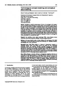
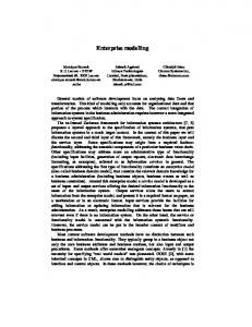
The metamodel contains all the required information for describing the components of the conceptual model, and its purpose is twofold. On the one hand, the metamodel represents the basic objects of the conceptual model in terms of metaclasses. On the other hand, the metamodel is used to evaluate the consistency and correctness of a given conceptual schema, and to serve as the basis for the mapping of the schema to an executable form. The ERT metamodel is shown in figure 9, whereas the CRL metamodel is shown in figure 10. Notice that these two metamodels are presented separarately for convenience only. The union of these two metamodels represents the entire metmodel of the proposed formalism (this being achieved through the common objects in the two metamodels such as entity). Also, for reasons of readability, the names of relationships are ommitted.
Relation Time_inter_ part_of_relation Inter_ part_of Total_involvement isa_relation
Inter_part_of relation
Part_of relation
Binary_ relation
Time_intra_ part_of_relation
isa_relation Partial_involvement isa_relation
Intra_ part_of Intra_part_of relation
Simple_isa Timestamped simple_entity_inv.
Timestamped simple_entity
Non_derived inter
Non_ derived inter Inter Derived inter
Timestamped Inter_relation
Entity involvement
Simple_ entity Simple
Inter_relation Timestamped_ derived_inter_ relation
Non_derived Simple_entity involvement
Simple involvement
Timestamped_ derived simple_entity_inv.
Timest_derived simple_entity
Derived_simple entity_involvem.
Derived Simple_entity
Derived inter
Derived_ Inter_relation
Derived
Time_complex entity_involv
Non_part_of relation
Timestamped Intra_relation Intra
Entity
Timestamped complex_entity
Complex involvement
Involvement
Complex_isa
Complex Complex_entity involvement
Complex_entity
Intra_relation Complex_ value_type Involvement
Complex_ value_type
Value_type involvement
Value_type Simple value_type involvement
Simple_ value_type
Figure 9: The ERT metamodel The ERT and CRL metamodels are represented as PROBE metaclasses using the basic object-oriented facilities discussed in the previous section. Space limitations prevent us from presenting the complete definition of the two metamodels. However, in order to exemplify their use, the definition of the metaclasses Entity and complex_value_type of the ERT metamodel and derivation_rule and Entity_population_constraint of the CRL metamodel are given.
Constraint Rule
Derivation_rule
Entity_population_ constraint
Action_rule
Population_ constraint Derived
Involvement_subset_ constraint
Involvement_equality_ constraint
Disjoint_involvement_ constraint
Derived_ inter
Complex_time_ expression
Value_constraint Time_expression
Disjoint_relationship_ constraint
Realationship_subset_ constraint
Implicit_time_ expression
Time_interval Uniqueness_constraint
Entity
Before
After
Time_slice
Time_unit
Value_type Real Date
String
Time
Complex_set_ expression
Arithmetic_ comparison
Number
Arithmetic_ expression
Variable
Logical_ operator
Set_ population
Figure 10: The CRL metamodel metaclass: isa: slots,
Entity, Metaclass,
property: name, [type = String, presence = mandatory], property: is_a_sub_class_of_1, [type = List(Simple_isa), presence = optional, default = []], constraint: uniqueness_of_name, [category = invariant, definition = (this#name in(Entity)#name)], constraint: total_involvement_entity, [category = invariant, definition = (this is_in oneof [Simple,Complex])], endslots, endmetaclass. metaclass: isa: slots,
Complex_value_type, Value_type,
Comparison_ operator
property: involved_in, [type = List(Complex_value_type_involvement), presence = mandatory, card = 1 - U], constraint: disjoint_with_simple_value_type, [category = invariant, definition = (~(this is_in Simple_value_type))], method: Complex_value_type_init, [definition = value_type_init/2, category = Prolog], endslots, endmetaclass. metaclass : Derivation_rule, isa : Metaclass, slots, property : derived_object, [type = Undefined, presence = mandatory, cardinality = 1-1], property : derivation_part, [type = Undefined, presence = mandatory, cardinality = 1-1], constraint : possible_derived_objects, [category = invariant, definition = (this#derived_object is_in oneof[ Derived, Derived_inter] )], constraint : possible_derivation_parts, [category = invariant, definition = (this#derivation_part is_in oneof[ Complex_set_expression, Complex_timestamped_set_expression] )], endslots, endmetaclass. metaclass : isa : slots,
Entity_population_constraint, Constraint_rule, property : on_class, [type = Entity, presence = mandatory, cardinality = 1-1], property : with_limits, [type=Arithmetic_comparison,presence =mandatory,cardinality = 1-1], property : at_time, [type = Time_expression, presence = mandatory, cardinality = 1-1],
endslots, endmetaclass.
The definition of these metaclasses is self explanatory if the metamodels of figure 9 and 10 are taken into consideration. More specifically, each metaclass represents a basic object of the conceptual modelling formalism in terms of its property slots, constraint slots etc. When defining an instance of this metamodel i.e., defining the application domain, the above definitions can be used to evaluate the consistency and correctness of this conceptual schema and moreover, provide the necessary basis for effective validation of the application domain knowledge by mapping the conceptual schema to an executable form. 4.
Validation through executable specifications
The prototyping paradigm is gaining much support in the software engineering community as an improvement over other traditional development paradigms. Prototyping, as a
development activity, normally starts in earnest at the design phase and most prototyping techniques concentrate on the user-interface issues. We propose that prototyping can and should be employed at an earlier phase i.e. that of requirements capture and specification. A special kind of ‘prototyping’ is proposed in this section, one that augments other validation techniques with an approach which encourages ‘simulation’ of the behaviour of the modelled domain. We use the term semantic prototyping in the context of conceptual model validation [Loucopoulos & Karakostas, 1989] to denote that our approach aims at checking the semantic correctness of a conceptual model. A conceptual model is to describe a Universe of Discourse only if it belongs to its interpretations. An inconsistent conceptual model admits no interpretations and consequently it can describe no Universe of Discourse. Semantic prototyping can be described as a top down experimental approach refining the various aspects of a conceptual model as inconsistencies are discovered. The approach tries to prove that a conceptual model is incorrect by proving that it is inconsistent, and also to increase the possibility that the conceptual model is correct (with respect to the modelled reality) by testing it against realistic situations. The mapping mechanism, which transforms system specifications, expressed in ERT and CRL, to PROBE expressions, makes it possible for conceptual specifications, which represent objects and business rules, to be executed. Thus, since the expressions of the conceptual modelling language have been mapped to executable code, they can result in a prototype of the system under development, and through its execution they can be checked for their correctness and consistency. Prototyping in this sense is not concerned with screen and dialogue specifications. All intensional knowledge is checked through corresponding extensional knowledge. A run-time environment developed for checking, compiling and executing PROBE programs can be used as an animation tool for executing the PROBE code that represents a conceptual model originally defined in ERT and CRL. The adopted approach is aimed at proving that the specific conceptual model can simulate (interpret) the organisation environment and its behaviour. The method used tries to increase the possibility that the conceptual model is correct by testing it against realistic situations. More specifically, a set of realistic data from the organisation environment are gathered, and the conceptual model is evaluated against them. Also, the model is tested with data that are deliberately false. During that process a refinement of constraints can also take place, i.e. we realise that some constraints are too strong that they admit no models at all, while others are too weak that they do not act as constraints at all. As an example of how the model validation is carried out, consider the ERT of figure 2 and an entity population constraint limiting the number of instances of the entity class Department. Let us assume that this constraint is :
Number of (Department) < 20 and >= 2 This constraint will be implemented in Probe as a constraint slot within the class definition of the entity class Department, as shown bellow : class: Department, isa: Class, in: Timestamped_simple_entity, slots, propValues, involved_in = [Department_has_Dept_name, Department_develops_Product, Department_employs_Employee], name = @ Department, endPropValues, constraint : population_of_dept, [category = invariant, definition = (_instances = listof(this), _num = number(_instances), _num < 20 and _num >= 2)], endslots, endclass.
The above class definition together with the definitions of the rest classes of that particular ERT will be stored in the internal database of Probe. In order to check the above constraint, we create two instances of the entity class Department and then we try to delete one of these from the Probe database. Then the constraint population_of_dept of the class Department is violated, and two error messages are issued : *** Run-time error 5512 : Department : unsatisfied constraint in the current KB. *** Run-time error 4024 : Given instance cannot be deleted in the current KB. 5.
Conclusions
Contemporary approaches to information system development, whilst attempting to improve the management of developing such systems through the use of software engineering methods and CASE, have paid little attention to the requirements for effective system evolution and for using information systems for effecting changes at the strategic level of organisations. The process of information systems development can be viewed as a sequence of modelbuilding activities. The quality of each set of models depends largely on the ability of a developer to extract and understand knowledge about an application domain which needs to be acquired form a diverse user population. This implies that developing an information system and in particular capturing user requirements is a knowledge intensive activity which requires appropriate mechanisms for ‘knowledge elicitation’, ‘knowledge representation’ and ‘knowledge validation’ about the modelled application domain. The premise behind the work reported in this paper is that one such knowledge source which plays a central role in any
information system is the set of business rules that establish the enterprise objectives and policy that establish the framework for the permitted behaviour of the information system. This paper seeks to demonstrate how a set of business rules may be interpreted by analysts in terms of the objects that exist in the organisation and their structural relationships (using the ERT model) and the rules that are expressed by references to these objects (using the CRL). Furthermore, the paper demonstrates how this user-oriented specification can be translated into an Object-Oriented executable specification which can serve as the basis of validating the captured knowledge. The formality of the approach allows for proving the model for various purposes, while the semantic prototyping technique enables a designer to validate the model by suggesting modifications and identifying inconsistencies. References [Abiteboul et al, 1989] Abiteboul, S., Fischer, P.C., Schek, H-J. (eds) Nested Relations and Complex Objects in Databases, Lecture Notes in Computer Science #361, Springer-Verlag, 1989. [Adiba, 1987] Adiba, M.E. Modelling Complex Objects for Multimedia Databases, in Entity-Relationship Approach: Ten Years of Expirience in Information Modelling, S. Spaccapietra (ed), NorthHolland, 1987. [AFCET, 1987] Proceedings of the IFIP 8/WG8.1 Working Conference onTemporal Aspects in Information Systems, Sophia Antipolis, France, May 1987. [Allen, 1983] Allen J.F. Maintaining Knowledge about Temporal Intervals, CACM, 26(11) Nov.1983. [Balzer et al , 1983] Balzer, R., Cheatham, T.E, Green, C. Software Technology in the 1990's: Using a New Paradigm, Computer, November 1983, pp. 39-45. [Casanova & Bernstein, 1979] Casanova M.A., Bernstein P.A, The Logic of a Data Manipulation Language, In Conference Record of the Sixth Annual ACM Symposium on Principles of Programming Languages (San Antonio, Texas), ACM, New York, 1979. [Clifford and Warren, 1983] Clifford J., Warren D.S. Formal Semantics for Time in Databases, ACM TODS Vol.8, No.2, June 1983. [Clifford & Rao, 1988] Clifford J., Rao A., A Simple, General Structure for Temporal Domains, in [AFCET, 1987]. [Fjeldstad et al, 1979] Fjeldstad, R.K. et al (1979) Application program maintenance, in Parikh & Zveggintzov (1983) 'Tutorial on Software Maintenance', IEEE, pp.13-27. [Haskin, 1982] Haskin, R.L., Lorie, R.A. On Extending the Functions of a Relational Database System, Proc. ACM SIGMOD Conference, Orlando, 1982. [Kim et al, 1987] Kim W., Banerjee J., Chou H.T., Garza J.F., Woelk D. Composite Object Support in ObjectOriented Database Systems, in Proc. 2nd Int. Conf. on Object-Oriented Programming Systems, Languages and Applications, Orlando, Florida, Oct. 1987. [Kim et al, 1989] Kim W., Bertino E., Garza J.F. Composite Objects Revisited, SIGMOD RECORD 18(2), June 1989. [Ladkin, 1987] Ladkin, P. Logical Time Pieces, AI Expert, Aug, 1987, pp.58-67.
[Loki, 1986] ESPRIT P107- LOKI, A Logic Oriented Approach to Knowledge and Databases Supporting Natural Language User Interfaces Institute of Computer Science, Research Center of Crete, Greece, March 1986. [Lorie & Plouffe, 1983] Lorie R., Plouffe W. Complex Objects and Their Use in Design Transactions, in Proc. Databases for Engineering Applications, Database Week 1983 (ACM), San Jose, Calif., May 1983. [Loucopoulos, 1989] Loucopoulos, P. The RUBRIC Project-Integrating E-R, Object and Rule-based Paradigms, Workshop session on Design Paradigms, European Conference on Object Oriented Programming (ECOOP), 10-13 July 1989, Nottingham, U.K. [Loucopoulos et al, 1990] Loucopoulos, P., McBrien, P., Persson, U., Schumaker, F., Vasey, P, (1990) TEMPORA Integrating Database Technology, Rule Based Systems and Temporal Reasoning for Effective Software, In Proceedings of ESPRIT '90 Conference, Brussels, November 1990. [Mathur, 1987] Mathur, R.N. (1987) Methodology for Business System Development, IEEE Transactionson Software Engineering, Vol.SE-13, No.5, May 1987, pp.593-601. [McKenzie, 1986] McKenzie E., Bibliography : Temporal Databases, ACM SIGMOD, Vol.15, No.4, December 1986. [Nicolas, 1978] Nicolas, J.M., First Order Logic Formalization for Functional, Multivalued and Mutual Dependencies, Proc. ACM SIGMOD Intr. Conf on Management of Data (Austin, Texas), ACM, New York, 1978. [Nicolas & Gallaire, 1978] Nicolas, J.M., Gallaire, H., Data Base: Theory vs Interpretation, In Logic and Data Bases, Gallaire, H., Minker, J. (eds), Plenum Press, New York, 1978. [Nicolas & Yazdanian, 1978] Nicolas, J.M., Yazdanian, K. Integrity Checking in Deductive Databases, In Logic and Data Bases, Gallaire, H., Minker, J. (eds), Plenum Press, New York, 1978. [Rabitti et al, 1988] Rabitti F., Woelk D., Kin W. A Model of Authorization for Object-Oriented and Semantic Databases, in Proc. Int. Conf. on Extending Database Technology, Venice, Italy, March 1988. [Smith & Smith, 1977] Smith J.M., Smith D.C.P., Database Abstractions: Aggregation and Generalization, ACM TODS 2(2), June 1977. [Theodoulidis et al, 1990a] Theodoulidis, C., Wangler, B. and Loucopoulos, P. Requirements Specification in TEMPORA, 2nd Nordic Conference on Advanced Information Systems Engineering (CAiSE90), Kista, Sweden, 1990. [Theodoulidis, 1990b] Theodoulidis, C. A Declarative Specification Language for Temporal Database Applications, PhD Thesis, UMIST, 1990. [Theodoulidis & Loucopoulos, 1991] Theodoulidis, C. and Loucopoulos, P. The Time Dimesion in Conceptual Modelling, Information Systems, 16(3), 1991. [Van Assche et al, 1988] Van Assche, F., Layzell, P.J., Loucopoulos, P., Speltincx, G., Information Systems Development: A Rule-Based Approach, Journal of Knowledge Based Systems, September, 1988, pp. 227-234. [van Griethuysen et al, 1982] van Griethuysen J.J. et al (eds). Concepts and Terminology for the Conceptual Schema and the Information Base, Report ISO TC97/SC5-N695/WG3 , 1982. [Villain, 1982] Villain M.B. A System for Reasoning about Time Proceedings of AAAI-82, Pittsburgh, Pa., Aug.1982.