We have applied our method to a real-life fall detection appli- cation from the geriatric care ..... TSP is defined as finding a hamiltonian cycle (a tour) of a graph.
Cache-aware Optimization of BAN Applications Yun Liang
Lei Ju
Samarjit Chakraborty
Tulika Mitra
Abhik Roychoudhury
Department of Computer Science, National University of Singapore
{liangyun, julei, samarjit, tulika, abhik}@comp.nus.edu.sg ABSTRACT
Body-area sensor network or BAN-based health monitoring is increasingly becoming a popular alternative to traditional wired biomonitoring techniques. However, most biomonitoring applications need continuous processing of large volumes of data, as a result of which both power consumption and computation bandwidth turn out to be serious constraints for sensor network platforms. This has resulted in a lot of recent interest in design methods, modeling and software analysis techniques specifically targeted towards BANs and applications running on them. In this paper we show that appropriate optimization of the application running on the communication gateway of a wireless BAN and accurate modeling of the microarchitectural details of the gateway processor can lead to significantly better resource usage and power savings. In particular, we propose a method for deriving the optimal order in which the different sensors feeding the gateway processor should be sampled, to maximize cache re-use. Our case study using a faint fall detection application – from the geriatric care domain – which is fed by a number of smart sensors to detect physiological and physical gait signals of a patient show very attractive energy savings in the underlying processor. Alternatively, our method can be used to improve the sampling frequency of the sensors, leading to higher reliability and better response time of the application.
Categories and Subject Descriptors C.3 [Computer Systems Organization]: Special-purpose and application-based systems—Real-time and embedded systems
General Terms Algorithms, Performance, Design
Keywords Sensor networks, Body-area networks, Cache, Mobile devices
1.
INTRODUCTION
Body-area sensor networks (or BANs) and related wearable computing technologies have lately become very popular, particularly in the context of biomonitoring applications. Well-known projects and prototype architectures in this area include MIThril [4], CustoMed [11], Wearable e-Textiles [5], Wearable Motherboard [17], e-Textile [12], and RFab-Vest [10]. Growth in this area has been largely fueled by the recent technological advancements in embedded processors, availability of lightweight sensor nodes, and advances in wireless networking. As a result, BAN-based health
Permission to make digital or hard copies of all or part of this work for personal or classroom use is granted without fee provided that copies are not made or distributed for profit or commercial advantage and that copies bear this notice and the full citation on the first page. To copy otherwise, to republish, to post on servers or to redistribute to lists, requires prior specific permission and/or a fee. CODES+ISSS’08, October 19–24, 2008, Atlanta, Georgia, USA. Copyright 2008 ACM 978-1-60558-470-6/08/10 ...$5.00.
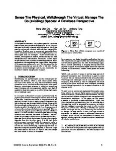
Figure 1: Data from different sensors triggering different parts of the application on the gateway processor.
monitoring is increasingly becoming a viable alternative to traditional wired biomonitoring techniques, which require a patient to be hospitalized and hooked up to large monitoring equipments. However, most biomonitoring applications require continuous processing of large volumes of data streams arriving through multiple sensors. As a result, both computation bandwidth and power consumption turn out to be serious constraints while designing sensor network-based computing platforms for high-end biomonitoring applications. This has led to a trememdous interest in architectures, design methods and software analysis techniques specifically targeted towards wireless BANs and wearable-computing related applications such as biomonitoring (for example, see [6, 7, 11, 13] and the references therein). Our contributions: In this paper we propose a disciplined method to optimize applications running on the communication gateway of a wireless BAN by exploiting the microarchitecture of the processor and the code layout of the application in memory. More specifically, we show how to compute the optimal order in which the different sensors feeding data into the gateway processor should be sampled in order to maximize the cache re-use. Techniques for optimal code/data [16, 18] placement to maximize cache re-use – which are related to the problem we address in this paper – have been well-studied in the embedded systems literature along with techniques for optimally configuring a cache [8]. But the problem of optimizing applications processing data from multiple sensors has not received sufficient attention so far. An important difference between well-known cache-aware code/data placement techniques and the problem we address here is that the former case is primarily concerned with static data. On the other hand, we are concerned with data streams, where different data items trigger different parts of the application code. We have applied our method to a real-life fall detection application from the geriatric care domain, which is fed by eight different smart sensors connected to a patient’s body. By using a combination of physiological and physical gait signals, this fall de-
tection application is able to distinguish between regular motion (e.g., walking and stair climbing) and the onset of an imminent fall. Once the possibility of such a fall is detected, various precautionary measures can be activated or an alarm might be triggered to call for help. Hence, the application has strict real-time requirements; an increased sampling rate of the sensors increases the reliability and responsiveness; and finally — as with all other applications in this class — it should incur low battery energy consumption. Clearly, these goals contradict each other and complicate the design of both the underlying hardware and the software, especially when combined with additional requirements like lightweight, ease of use, and small form-factor. Hence, this calls for careful optimization and co-design of the hardware and the software. Our results show that the order in which the eight sensors are sampled in each round (which does not affect the functionality of the application) has a significant effect on the degree of instruction cache re-use and hence the processing time of the sensor data. Ignoring this sampling order can lead to up to 40% increased energy expenditure in the gateway processor. Alternatively, the reduction in processing time can be exploited to increase the sampling rate of sensors, which leads to improved reliability and responsiveness of the application. Overview of the proposed method: A high-level overview of our setup is shown in Figure 1. Data from multiple wireless sensors attached to a patient’s body arrive at a battery-operated gateway processor (also strapped to the patient), which runs various biomonitoring applications implementing fall detection, electrocardiogram (ECG) analysis, etc. Often such applications are run on regular personal mobile devices such as mobile phones or PDAs. However, given that such devices usually have large form-factors and short battery life, there is an increasing trend towards building customized gateways that have been tailored for specific biomonitoring applications. We assume such an application-specific gateway having a lightweight processor (running at 60 - 80 MHz) with a small instruction cache. Depending on the sensor from which the data arrives, different parts of the application code are triggered. However, often there is a significant overlap between the codes corresponding to two different sensors. As the processing time of any sensor data depends on the state of the instruction cache (that is determined by the previously executed code blocks), the specific order in which data from different sensors is processed has a significant impact on the number of instruction cache misses and hence the processing time. Towards this, our cache modeling relies on fixed-point construction-based analysis of program semantics [15] and is similar to the ones used for estimating the so-called cache-related preemption delay (see [14]). When the number of sensors in question is relatively small, it may be feasible to exhaustively enumerate all possible sensor orderings, compute the processing time corresponding to each of these orderings by accurately modeling the instruction cache states, and finally select the ordering with the smallest processing time. However, this scheme breaks down when the number of sensors start increasing. For high-end biomonitoring applications, the number of sensors can easily exceed 20 (e.g., 12 sensors for ECG monitoring [13] plus 8 sensors for our fall detection application). For these many sensors, it is easy to see that exhaustively enumerating all possible sensor orderings can be ruled out. For such problems, we rely on modeling the instruction cache re-use from the last one sensor only. In other words, given an ordering of sensor nodes . . . , Si , Sj , Sk , when estimating the maximum execution time of the code for Sk , only the cache state resulting from processing Sj ’s data is accounted for; we ignore the cache
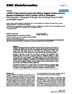
Figure 2: Structure of the fall detection application. state resulting from processing the data from Si and all previous sensors. Although this leads to some (safe) over-approximation of the processing time, this is done in order to contain the complexity of the problem. With this restricted cache modeling, our problem can be formulated as a standard traveling salesman problem (TSP). However, unlike versions of TSP that are anemable to reasonable approximations, the TSP arising in our case is a nonmetric, asymmetric TSP that cannot be approximated within any factor [3]. Hence, we have used the well-known Lin-Kernighan local search heuristic (LKH) [3], which is known to perform well for this class of TSP problems [9]. Organization of this paper: In the next section we describe our fall detection application in detail, followed by our cache modeling technique in Section 3 in conjunction with the exhaustive search for determining the optimal sensor ordering. We then present our restrictive cache modeling and discuss how it is used along with the LK heuristic. Experimental results are presented in Section 4. Finally, we conclude in Section 5 by discussing some directions for future work.
2. CASE-STUDY APPLICATION Any wearable fall detection system typically employs physical motion sensors such as tri-axial accelerometers and gyroscopes. The fall detection system we examine as a case study consists of one tri-axial (3D) MEMS accelerometer plus one gyroscope on the thigh position and another accelerometer on the waist position. The sensitivity axes of each accelerometer is arranged in lateral, vertical, and antero posterior directions. The gyroscope provides 2D angular (lateral and sagittal) motion information. Overall we have eight streams of sensor signals coming in from the physical motion sensors (lateral, vertical, antero-posterior for each accelerometer and lateral, sagittal for gyroscope) to the gateway device through ZigBee (802.15.4) wireless communication protocol. The sensor signals are sampled at 300 samples per second to detect the onset of falls. The fall detection algorithm runs on the gateway device. In the event that the onset of a fall is detected, the fall safety system is engaged that may attempt to minimize the injury through airbag inflation or prevent the fall through muscle constriction. In any case, the gateway device notifies the incident to the heath care providers or relative of the patient via mobile telephone networks (GPRS, 3G, etc.) or wireless LAN. The algorithm implementing fall detection first needs to transform the 3D accelerometer data to 2D angular data (lateral and sagittal). Next, it marks an angular motion of the thigh beyond a threshold as a “possible" onset of fall. For each such possible
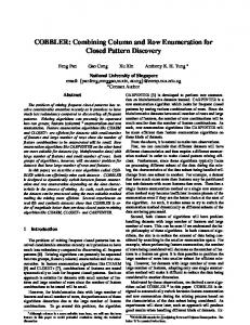
onset of fall, the correlation between thigh and waist angles as well as pattern matching of gyroscope angle (against reference values obtained from a number of actual falls) are used to eliminate false positives. A high-level overview of the functionalities of this application appears in Figure 2. Let us now examine the code sharing pattern among the program paths exercised by the eight different sensors in this application to intuitively understand the opportunities for instruction cache reuse. Figure 3 shows the different modules (procedures or functions) for a small fragment of the application code. Each of the sampled sensor data first undergoes discrete wavelet transformation by going through two complimentary filters (a low-pass filter and a highpass filter). However, the coefficients for the acclelerometer signals and gyroscope signals are quite different. So we have two different coefficient selection modules. Next, the accelerometer signals are calibrated and the calibration process is different for each signal. Finally, each 3D accelerometer signal is converted to 2D angular motion data by going through the appropriate 3D → 2D module. Figure 3 also shows the modules exercised to process the lateral motion from the waist accelerometer say S (left path) and the lateral motion from the gyroscope say S� (right path). Clearly, the processing of these two sensor data shares the FIR filter code. If S � is processed after S, then S � can take advantage of the common code left in the instruction cache by S (such as FIR filter code). Moreover, in this small fragment of the application, it is quite obvious that sampling the accelerometer signals first followed by gyroscope signals will provide maximum opportunities for cache reuse (as the code for coefficient selection may be reused in addition to FIR filter). In general it is non-trivial to manually identify the optimal sampling order of the different sensors for maximal cache re-use, especially when the number of sensors is large and/or the application is complex. Traditional code optimization approaches are oblivious to the context in which a sensor data is being processed. In other words, the processing of each sensor data is considered in isolation. Thus these code optimization techniques fail to exploit the cache reuse opportunities opened up by code sharing among the processing tasks of the different sensors. In the next section we present a systematic methodology to exploit maximal cache reuse through optimal sampling order of the sensors.
3.
OPTIMIZING BAN APPLICATIONS
In this section, we describe our optimization scheme based on micro-architectural modeling, in particular, cache modeling. Further, we determine the order in which the different sensors should be sampled to maximize the guaranteed cache re-use. As an example, consider two sensors S and S� — which are processed by programs P and P � . If the two programs are completely disjoint, we do not encounter any instruction cache re-use (owing to the execution of P ) while executing P � . However, typically, the processing of different pieces of sensed data share (a lot of) common code. Consequently, there is non-trivial cache re-use from the execution of P while we are executing P � . However, since P and P � are programs with many possible execution traces, the cache re-use (the number of cache hits thus accrued) is not a constant. Depending on the exact value of the sensor data — both P and P � may execute different paths. Executing a trace π1 of P just prior to a trace π1� of P � may produce many additional hits over executing some other trace π2 of P prior to another trace π2� of P � . Therein lies our notion of guaranteed cache re-use. The guaranteed cache re-use of a given ordering of sensors S1 , . . . , Sk stems from the commonality of the processing code for S1 , . . . , Sk irrespective of the paths executed in these processing codes. Note that this involves static
program analysis (we are analyzing the programs processing the sensor data). The static analysis results are used to find a sensor ordering which maximizes the guaranteed cache re-use.
3.1 Cache Behavior Summarization We now formally describe our static analysis method for computing cache behavior summary for a given application program. To model cache behavior, we first need the notion of a cache state. For simplicity of notation, let us assume a direct-mapped cache; the analysis can be straightforwardly extended for set-associative caches. For a direct-mapped cache with n blocks, a cache state cs is simply a mapping {1, . . . , n} → M ∪ {⊥}, where M is the set of code memory blocks being mapped to cache, and ⊥ indicates the situation where a cache block is empty. As a notational shorthand, we use cs[i] to denote the content of the ith cache block in cache state cs. Now, let us consider a program processing a particular sensed data. In order to statically summarize the overall cache behavior, we associate program points or control locations in the program with sets of cache states. We develop and use two quantities: Reaching Cache States (RCS) and Live Cache States (LCS). D EFINITION 1 (R EACHING C ACHE S TATES ). For a program point p in a program P rog, the set of reaching cache states RCS(p) is defined as the set of cache states with which p can be reached (via any incoming path to p in P rog). D EFINITION 2 (L IVE C ACHE S TATES ). For a program point p in a program P rog, the set of live cache states LCS(p) is the set of possible first references to cache blocks via any outgoing path from p in P rog. Given any program point p in program P rog, the quantities LCS(p) and RCS(p) are computed by exploring the paths to/from p in the control flow graph of P rog. This is done efficiently (without path enumeration) by (i) associating each program point with a LCS/RCS, (ii) defining the RCS of a program point using the RCS of its predecessors, and (iii) defining the LCS of a program point using the LCS of its successors. As a program contains loops, the above will produce a set of recursive equations on LCS/RCS that needs to be solved iteratively. Assuming empty cache at the beginning of the program, we can iteratively solve the recursive equations for LCS and RCS separately. This is done, until the LCS and RCS estimates at each program point is stable – that is, until the iterative computation reaches a fixed-point. The resultant RCS estimate for the exit point of the program is denoted as RCS(P rog); these are the possible cache states at the end of the program. Similarly, the LCS estimate at the entry point of the program is denoted as LCS(P rog); these are the possible first references to cache blocks during the program’s execution. Given a program P rogi processing a particular sensed data Si , the quantities RCS(P rogi ) and LCS(P rogi ) form the summary of the cache behavior for P rogi . Details of LCS and RCS computation for a program appear in [14].
3.2 Composition of Cache Summaries Consider the processing of various sensed data S1 , . . . , Sk where the processing of Si is done by application P rogi . In reality, for i �= j, applications P rogi and P rogj are not disjoint — they share non-trivial chunks of code. In the preceding, we have shown the cache behavior summarization of each individual application. Now we compose these cache summaries to tightly estimate the cache re-use from a given ordering of processing. When we say a given ordering S1 , . . . , Sk we mean that (i) data from these sensors are repeatedly obtained over many “rounds", and (ii) in each round,
Figure 3: A fragment of the application with different sensor data exercising different paths through the application. this operator, the set of possible cache states after the execution of P rog1 , P rog2 is simply RCS(P rog1 ) ⊕ RCS(P rog2 ). That is, the set of cache states is drawn from the execution of P rog2 (the application last executed), but for empty cache blocks their content is derived from RCS(P rog1 ). In a similar way, the set of cache states after the processing of sensed data S1 , . . . , Si (i.e., after executing P rog1 , P rog2 , . . . , P rogi ) is Reach1...i = RCS(P rog1 )⊕RCS(P rog2 )⊕. . .⊕RCS(P rogi )
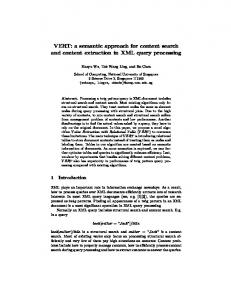
Figure 4: Computing Guaranteed Cache Re-use. the sensed data in that round are processed by executing P rog1 , followed by P rog2 , . . . , followed by P rogk . So, we need to estimate the minimum guaranteed cache re-use resulting from the execution of P rog1 , . . . , P rogk . At this stage, we are determining the cache behavior across applications. The cache behavior within an application is already summarized by the LCS/RCS quantities. The cache behavior across applications can be intuitively captured by queries like the following. • Given the execution of P rog1 , . . . , P rogi , what is the guaranteed cache re-use when we execute P rogi+1 ? To answer the above query, let us try to estimate the set of possible cache states after the execution of P rog1 , . . . , P rogi . For this purpose, we define a simple operation over cache blocks. Note that a cache block’s content is drawn from M ∪ {⊥} where M is the set of memory blocks and ⊥ is a symbol denoting empty cache block. We define: def m� if m� �=⊥ m ⊕ m� = m otherwise Thus m ⊕ m� is m� (the later content) unless it is empty. As a cache state is essentially a vector of cache block contents, the above operation can be lifted to cache states by applying the operation point-wise to individual cache blocks. (cs ⊕ cs� )[i] = cs[i] ⊕ cs� [i] 1 ≤ i ≤ n def
The operation can now be further lifted to sets of cache states CS, def
CS � as CS ⊕ CS � = {cs ⊕ cs� | cs ∈ CS, cs� ∈ CS � }. Using
Given the above set of cache states after the execution of P rog1 , . . . , P rogi , what is the minimum number of guaranteed cache hits when P rogi+1 is executed? To answer this, we need to see how the cache states at the end of P rog1 , P rog2 , . . . , P rogi can help (in terms of achieving cache hits) the possible first references to cache blocks in P rogi+1 . Recall, the possible first references to cache blocks in an application is summarized by the LCS of the application. So, the hit/miss scenarios encountered in P rogi+1 due to the prior execution of P rog1 , . . . , P rogi is Reach1...i LCS(P rogi+1 ) where Reach1...i is as defined in the preceding (using RCS quantities) and the operator defines cache state equality as follows. Given cache states cs, cs� we get a vector of boolean values as foldef
lows: (cs cs� )[i] = (cs[i] == cs� [i]). Thus, cs cs� checks whether the cache states cs, cs� are equal; for each cache block that is equal in content it stores the boolean value true (otherwise false). We can lift the operation over sets of cache states CS, CS� in the usual way: CS CS � def = {cs cs� | cs ∈ CS, cs� ∈ CS � } Hence, the set Reach1...i LCS(P rogi+1 ) summarizes all the hit/miss scenarios for the first cache block accesses in P rogi+1 owing to the prior execution of P rog1 , . . . , P rogi . The minimum guaranteed number of cache hits is given by: minh∈Reach1...i �LCS(P rogi+1 ) |h| where h is a vector of boolean values in Reach1...i � LCS(P rogi+1 ) and |h| is the number of occurrence of true in the boolean vector h. A schematic explanation of the guaranteed cache re-use computation appears in Figure 4. Here we show the processing of three sensors S1, S2, S3 and the guaranteed cache re-use encountered while processing S3 assuming prior processing of S1, S2. We have shown a direct-mapped cache with only two blocks for simplicity of explanation. Effect of the prior processing of S1, S2 is captured by RCS(S1) ⊕ RCS(S2). This set is computed by applying the ⊕ operator pairwise to the members of RCS(S1) and RCS(S2). Thus ⊥, m2� ⊕ m1, ⊥� = m1, m2�. Once RCS(S1) ⊕ RCS(S2) has been computed, we check for cache state equality with LCS(S3), the possible first references to cache
Sj s1 s2 s3 s4 s5 s6 s7 s8 s1 49 62 44 48 61 41 49 s2 25 33 54 40 45 39 49 Si s3 27 21 23 35 32 17 27 processing s4 32 54 35 41 33 18 36 order: s5 56 68 58 61 62 37 55 (Si , Sj ) s6 48 50 55 44 49 41 41 s7 36 43 43 41 32 42 59 s8 36 52 45 51 42 42 43 Best ordering: 378 cache hits for (S7 , S8 , S2 , S4 , S5 , S1 , S6 , S3 )
Table 1: Guaranteed cache reuse from previous sensor task. blocks in the processing of S3. Again, (RCS(S1)⊕RCS(S2)) LCS(S3) is computed by applying the operation pairwise. Thus, by applying to m1, m2� (a cache state in RCS(S1)⊕RCS(S2)) and m5, m2� (a cache state in LCS(S3)), we get the boolean vector f alse, true� signifying a cache hit in the second cache block. By analyzing all such possible hit/miss scenarios (in this simple example there are only two of them as shown in Figure 4), we calculate the number of guaranteed cache hits during the processing of S3 due to the prior processing of S1, S2. In the preceding discussion, we have detailed the cache behavior summarization for (a) any one application, and (b) across many applications, provided an ordering for their execution is given. We now describe how these cache behavior summaries can be exploited to produce an “optimal" ordering of the applications’ execution. The generated ordering is optimal in the sense that it maximizes cache re-use.
3.3 Determining Optimal Composition Order For an application with k sensors, in each ordering S1 , . . . , Sk , the cache re-use can be calculated as: k−1
(minh∈Reach1...j �LCS(P rogj+1 ) |h|) j=1
We can compute the cache re-use for all k! different orderings and find the “optimal" ordering with maximum cache re-use. However, for larger number of sensors, such an exhaustive search becomes infeasible. We propose to convert our problem of finding the “optimal" ordering into the well-known Traveling salesman problem (TSP). Given k sensed data for processing, (S1 , . . . , Sk ), we define a complete graph G where each vertex represents a sensor. The weight w(Si → Sj ) of the edge Si → Sj represents the guaranteed number of cache hits encountered while processing Sj owing to the processing of Si immediately prior to it. Thus def
w(Si → Sj ) = minh∈RCS(P rogi )�LCS(P rogj ) |h| Thus, we are only considering the application program P rogi that executed immediately before P rogj . We are not considering in the execution history which application program(s) executed prior to P rogi . Thus, the guaranteed cache re-use estimated by us will be a (safe) underestimate of the actual cache re-use. However, this under-estimation is relatively small, and ignoring it still produces near-optimal results. Finally, note that w(Si → Sj ) �= w(Sj → Si ) as the cache re-use of Si from Sj could be different from the re-use of Sj from Si . For a small fragment of our fall detection application, Table 1 shows the guaranteed number of cache hits for the task associated with sensor Sj if the immediately preceeding sensor whose data was processed is Si . The guaranteed cache hits for the optimal sampling order are indicated in bold face. It may be noted that even for such relatively few sensors, determining this order optimally in an ad hoc trial-and-error fashion might not be possible. Therefore, we formulate it as a TSP.
Figure 5: Execution requirements for different sensor orderings. TSP is defined as finding a hamiltonian cycle (a tour) of a graph G with minimum cost. To solve our problem as a TSP, we need to make the following modifications. (1) TSP finds hamiltonian cycles where each node is visited exactly once. However, our problem of searching for the best ordering is to find an acyclic path in the graph, where each node is visited exactly once. Hence, we add a dummy node Sk+1 to G. Edges Sk+1 → Si and Si → Sk+1 are set with weight 0 for all nodes Si (1 ≤ i ≤ k). The dummy node tells us where to break the cyclic tour to generate the optimal linear ordering. (2) While TSP returns a tour with the minimum cost, we need to find a path with maximum cost instead (maximum cache re-use). Hence, for each edge, weight w(Si , Sj ) is modified to Const − w(Si , Sj ) for all edges, where Const is a large constant bigger than any edge weight of G. After these two modifications above, we apply the well-known Lin-Kernighan local search heuristic (LKH) [9] to find the tour of G with minimum cost. LKH is known to perform well for nonmetric, asymmetric TSP; it produces near-optimal results for our experiments as well.
4. EXPERIMENTAL RESULTS We have conducted two different classes of experiments. The first using the full-fledged fall detection application that was described in Section 2. Here, our experiments illustrate the utility of our proposed cache modeling in tightly estimating the gateway processor’s minimum clock frequency and reducing its power dissipation. Our second class of experiments are based on synthetic data and a larger number of sensors (15 - 20 in number). Here, our main goal is to illustrate the minimal loss in accuracy as a result of the restrictive cache modeling.
4.1 Case Study: Fall Detection Application Recall that our application has three sensor inputs from the accelerometer and two from the gyroscope attached to the thigh, and three sensor inputs from the accelerometer attached to the waist (Figure 2). For the gateway, we have assumed a light-weight processor with single-issue in-order pipeline, 1 KB direct-mapped instruction cache (128 cache sets, 8 bytes block size) and 100 cycles cache miss penalty. We have also used a “natural” code layout that resulted from compiling the original C code of the application using SimpleScalar GCC compiler [1]. For all power estimates, we used Wattch [2] along with the SimpleScalar instruction set simulator. Our experimental results show that the number of processor cycles required for processing all the data from one round of sampling (i.e., one data sample from each of the eight sensors) is equal to 248,657 cycles, when no inter-application (i.e., processing code for different sensors) cache reuse is modeled. In other words, the instruction cache is assumed to be empty before the application code
thetic data. We assigned random weights (within appropriate constraints) for cache re-use between two sensor nodes as well as three sensors sequences. However, as cache sizes in gateway devices are quite small, we do not model cache reuse beyond two sensor nodes. We compare the quality of the solutions (in terms of guaranteed cache hits) returned by TSP formulation and exhaustive search for 12 sensor nodes. The TSP formulation returns optimal or nearoptimal solutions (with more than 95% accuracy) in all the cases. Moreover, we observed that exhaustive search is scalable only up to 15 sensors. But our TSP formulation in conjunction with the LK heuristic returns an ordering within few seconds for hundreds of sensors. Figure 6: Memory latency reduction for sensor data processing tasks.
5. CONCLUDING REMARKS
for each sensor starts executing. With inter-application cache modeling, an optimal ordering of the sensors results in 206,357 cycles, whereas the worst-case ordering results in 224,057 cycles. Note that the chances of an arbitrary ordering being close to the optimal is fairly low. This is illustrated in Figure 5 where the range of execution requirements (i.e., number of processor cycles) for one round of processing has been partitioned into 10 equal-sized bins (horizontal axis). Each bar in this figure represents the number of sensor orderings that result in the execution requirement corresponding to the associated bin. The bin with the lowest execution requirement (first bin) contains only 23 of the 8! different possible sensor orderings. This illustrates the need for a systematic approach to optimize the sensor sampling order. The importance of accurate cache modeling is illustrated in Figure 6, which shows the memory latencies (in number of processor cycles) for the tasks associated with the different sensors, with and without cache modeling. It also shows the reduction in memory latency with optimal ordering (except for sensor 7, which being the first sensor in this ordering cannot exploit any cache reuse). With a sampling rate of 300 samples/sec and no inter-task cache modeling, the processor is estimated to be clocked at 74.6 MHz. With the same sampling rate, but with inter-task cache modeling the estimated minimum clock frequencies drop to 67.2 MHz and 61.9 MHz for the worst and the best sensor orderings. Hence, without accurately modeling the instruction cache and ignoring the sampling ordering of the sensors can lead to running the processor at a 21% higher clock frequency. Results returned by the Wattch simulator show that the average energy consumption per sampling round corresponding to these cases are 32.84 mJ and 23.41 mJ. Ignoring the effects of the cache and the sensor ordering can therefore lead to 40% extra energy expenditure per sampling round, thereby illustrating the benefits of our proposed scheme.
In this paper we have proposed a methodical cache-aware optimization technique for wireless BANs. Our results — with a reallife application — show that appropriate modeling of the gateway processor’s cache, coupled with carefully determining the order in which the sensors are sampled can lead to significant energy savings. In this work we have assumed a fixed code layout in the memory. As a part of future work, it would be interesting to use optimal code placement strategies in conjunction with the techniques developed in this paper, for further improving execution time estimates and energy consumption.
4.2 Accuracy For large number of sensors, exhaustively enumerating all possible sensor orderings is not feasible. Hence, we rely on the TSP formulation of the problem (as described in Section 3.3) to identify the optimal ordering. The question remains about the quality of the solutions returned by this TSP formulation. There are two sources of approximations in this formulation: (1) it maintains a limited cache history, and (2) it applies the LK heuristic to solve the TSP problem. While the sub-optimality due to the LK heuristic is a well studied issue (see [3]), the effect of the first approximation is unknown. First, we observe that for our case study, there exists up to 5% additional guaranteed cache reuse beyond the immediate predecessor sensor. But the TSP formulation returns identical sensor orderings as the exhaustive search. To confirm the generality of this result, we modeled cache reuse beyond just the immediate predecessors in an experiment with syn-
6. ACKNOWLEDGMENTS This work is supported by A*STAR SERC project R-252-000258-305. We would like to thank Francis Eng Hock Tay and Nyan Myo Naing for sharing the fall detection application with us.
7. REFERENCES [1] T. Austin, E. Larson, and D. Ernst. SimpleScalar: An infrastructure for computer system modeling. IEEE Computer, 35(2), 2002. [2] D. Brooks, V. Tiwari, and M. Martonosi. Wattch: A framework for architectural-level power analysis and optimizations. In ISCA, 2000. [3] S. Dasgupta, C. H. Papadimitriou, and U. Vazirani. Algorithms. McGraw-Hill, 2006. [4] R. W. DeVaul et al. MIThril 2003: Applications and architecture. In International Symposium on Wearable Computers, 2003. [5] J. Edmison et al. E-Textile based automatic activity diary for medical annotation and analysis. In International Workshop on Wearable and Implantable Body Sensor Networks, 2006. [6] I. Al Khatib et al. A multiprocessor system-on-chip for real-time biomedical monitoring and analysis: Architectural design space exploration. In DAC, 2006. [7] E. Farella et al. A wireless body area sensor network for posture detection. In IEEE Symposium on Computers and Communications, 2006. [8] A. Ghosh and T. Givargis. Cache optimization for embedded processor cores: An analytical approach. TODAES, 9(4), 2004. [9] P. Gupta, A. B. Kahng, and S. Mantik. Routing-aware scan chain ordering. TODAES, 10(3), 2005. [10] R. Jafari et al. Adaptive and fault tolerant medical vest for life-critical medical monitoring. In ACM Symposium on Applied Computing, 2005. [11] R. Jafari et al. Wireless sensor networks for health monitoring. In International Conference on Mobile and Ubiquitous Systems, 2005. [12] J.-C. Kao and R. Marculescu. On optimization of e-textile systems using redundancy and energy-aware routing. IEEE Trans. on Computers, 55(6), 2006. [13] I. Al Khatib et al. Performance analysis and design space exploration for high-end biomedical applications: Challenges and solutions. In CODES+ISSS, 2007. [14] H. S. Negi, T. Mitra, and A. Roychoudhury. Accurate estimation of cache-related preemption delay. In CODES+ISSS, 2003. [15] F. Nielson, H. R. Nielson, and C. Hankin. Principles of Program Analysis. Springer, 2004. [16] P. R. Panda, N. D. Dutt, and A. Nicolau. Memory data organization for improved cache performance in embedded processor applications. TODAES, 2(4), 1997. [17] S. Park, K. Mackenzie, and S. Jayaraman. The wearable motherboard: A framework for personalized mobile information processing (PMIP). In DAC, 2002. [18] H. Tomiyama and H. Yasuura. Code placement techniques for cache miss rate reduction. TODAES, 2(4), 1997.