MATEC Web of Conferences 251, 04048 (2018) IPICSE-2018
https://doi.org/10.1051/matecconf/201825104048
Calculation of wave conditions in water area with sharp bottom unevenness Igor Kantarzhi and Alexander Gogin* Moscow State University Of Civil Engineering, Yaroslavskoe shosse, 26, Moscow, 129337, Russia
Abstract. Design of marine hydraulic structures is associated with definition of design wave conditions close by these structures. Safety and economy of hydraulic structures depend exactly on characteristics of wave conditions. In this paper, we consider two methods of obtaining the design wave: analytical calculation using Building Codes and Regulations of Russia and numerical modeling. The MIKE 21 software package was used in this case to perform the numerical simulation. A feature of the considered area is the unevenness of the bottom relief of the water area. The purpose of the article is to show clearly, how much characteristics of the design wave can be overstated when calculating in according to the normative document that does not take into account features of the water area.
1 Introduction Design of marine hydraulic structures (protective piers and breakwaters, coast protection structures, berths, etc.) is necessarily associated with definition of wave conditions close by these structures. Characteristics of wave conditions are properties of separate wave’s oscillations in time and space. A typical problem by design of marine hydraulic structures is the lack of full-scale data about wave conditions in an interest area. In turn, safety and economy of hydraulic structures depend exactly on characteristics of wave conditions. There is a large number of methods used to become a design wave, which probability meets requirements for designing structures of a certain importance class. They can be divided into three main groups - analytical calculation using Building Codes and Regulations, physical and numerical modeling. The main normative document used in Russia and providing the definition of the calculated wave parameters is SP 38.13330.2012 “Loads and impact on hydraulic structures” [1]. In this document is recommended the method of calculating elements of waves in deep water along the wind fields. Since this design method should be applied to the whole variety of coastal sea’s zone, averaged approaches were proposed, what was noted by authors of these methods [2, 3]. Although these methods are supplemented by some empirical coefficients, they remain averaged and allow unpredictable errors by using to specific conditions of the design area. It is expected, that errors in determining of wave’s design parameters will be compensated by the engineering reserves accepted in the design. *
Corresponding author:
[email protected]
© The Authors, published by EDP Sciences. This is an open access article distributed under the terms of the Creative Commons Attribution License 4.0 (http://creativecommons.org/licenses/by/4.0/).
MATEC Web of Conferences 251, 04048 (2018) IPICSE-2018
https://doi.org/10.1051/matecconf/201825104048
However, this approach is not applicable for most important structures. Most likely, these circumstances caused the inclusion in the normative document the following requirement: “Loads from waves and ice to first class hydraulic structures, as well as calculated wave parameters in open and enclosed water areas, should be improved by natural observations and laboratory studies" [4]. Experience has shown that almost all designed constructions have features that require verification of calculations according to the normative document. In this article, we will consider one such case. A special feature of this case is the sequence of underwater reefs at the entrance to the considered water area, which theoretically can influence the wave regime in the area, but can not be taken into account in calculations according to the normative document, which takes into account only unevenness with several wave lengths size. In this paper, we considered and analyzed calculation’s results of wave according to the normative document and results obtained with numerical simulation, and compared these methods at the point near designed constructions by following characteristics: mean wave height, mean wave period and mean wave length. The research was carried out by designing the seaport on the Novaya Zemlya Island in the Arctic Ocean in the Bezymiannaya Bay. The simulated area is represented in Figure 1. Аs it was said above, the feature of the considered water area is the unevenness of bottom relief at the entrance in the bay, intersected by underwater elevations, depressions and gutters, which largely influences the wave mode. Taking into account this feature is the most important in this paper. Calculation of wave’s elements will be made by the wind with speed 25 m/s of the most dangerous direction for wave formation (northwest). Duration of the wind was 6 hours. The water depth in the design point marked as “1” is 5 m.
Fig. 1. Situational plan of the calculations area
The analysis of published works on numerical modeling of the wave propagation shows that these works do not call the sufficient attention to the methodology of comparing obtained wave characteristics. Specialty in scientific works, there was no comparison of numerical modeling’s results with results of calculations based on the method according to the normative document.
2
MATEC Web of Conferences 251, 04048 (2018) IPICSE-2018
https://doi.org/10.1051/matecconf/201825104048
The purpose of this article is to clearly compare results of wave elements calculation using fundamentally different methodologies, as well as a detailed analysis of the comparison result.
2 Methods The study was done in 2018 by the designing a seaport in the Bezymiannaya Bay on the Novaya Zemlya Island as development part of maritime infrastructure in the Arctic Ocean. Described above method of the determining design characteristics of waves according to the normative document is an equivalent wave method [5]. A design storm is determined corresponding to the class of the structure in accordance with the function of a distribution of wind speed in wave formation direction. This design storm is assumed equivalent to the storm regime for the construction area. Calculation according to the normative document implies the propagation of waves along a beam and the dependence characteristics of wave elements on the acceleration length equal to the distance from the design point to an intersection of the beam with the shore, on the speed and direction of the wind. In this case, as a result of the calculation, we can obtain wave height. Also, as a result of the calculation, we can get mean wave period and mean wave length. Consideration of the sharp bottom heterogeneity in the simplified calculation method by [1] is not provided. The MIKE 21 software package was used in this case to perform the numerical simulation. The choice of this complex was caused an unstructured mesh that provides more accurate representation of the area, what is the main advantage of MIKE 21. The application of the 2D model is considered to be sufficiently accurate to describe the construction area [6]. To carry out above described calculations, we used the spectral wave model DHI MIKE 21 - Spectral waves. The spectral module describes the formation, growth, dissipation and transformation of waves in time and space, depending on wind fields. The fully spectral formulation is based on the wave action conservation equation. Equations are formulated in either Cartesian co-ordinates for small-scale applications or polar spherical co-ordinates for large-scale applications. The discretization of the governing equation in geographical and spectral space is performed using cell-centered finite volume method. In the geographical domain, an unstructured mesh technique is used. The time integration is performed using a fractional step approach where a multi-sequence explicit method is applied for the propagation of wave action [7]. In MIKE 21 SW, the wind waves are represented by the wave action density spectrum, 𝑁 (𝜎, 𝜃). The independent phase parameters have been chosen as the relative angular frequency, 𝜎 = 2𝜋𝑓, and the direction of wave propagation, 𝜃. The relation between the relative angular frequency and the absolute angular frequency is given by the linear dispersion ratio [7]: 𝜎 = √𝑔𝑘 tanh(𝑘𝑑) = 𝜔 − 𝐤 ∙ 𝐔,
(1)
where 𝑔 – the acceleration of gravity; 𝑑 – water depth; 𝜔 – the absolute angular frequency; 𝐤 – the wave number vector with magnitude k and direction 𝜃; 𝐔 – the current velocity vector. The action density, 𝑁 (𝜎, 𝜃), is related to the energy density, 𝐸 (𝜎, 𝜃), как [7]: 𝑁=
3
𝐸 𝜎
(2)
MATEC Web of Conferences 251, 04048 (2018) IPICSE-2018
https://doi.org/10.1051/matecconf/201825104048
To calculate wave characteristics on the approach to design constructions, the wave regime was modeled in all water area of the Bezymiannaya Bay. The unevenness of the bottom relief is taken into account in the numerical simulation by the directly introducing into the bathymetry model of the bay, which is presented in Figure 2. Wind parameters were integrated into the model with a constant speed and azimuth of the wind action over the entire considered water area.
Fig. 2. The bathymetry model of the Bezymiannaya Bay
Values of additional coefficients (wave breaking coefficient, bottom roughness coefficient and coefficients determining the energy dissipation at deep water) were saved by default and are given in Table 1. Table 1. Additional coefficients Parameter
Wave breaking coefficient Bottom roughness coefficient Coefficients determining the energy dissipation at deep water
𝐶𝑑𝑖𝑠
Value 0,8 0,04 m = 4,5; 𝛿𝑑𝑖𝑠 = 0,5
3 Results Calculation according to the normative document was carried out in strict accordance with instructions of the calculation methodology. Accepted initial data and calculation results in design point are given in tabular form in Table 2, where Vw – the design wind speed; Ln – the acceleration length of waves; ̅̅̅ ℎ𝑑 – the mean wave height; ̅̅̅ 𝑇𝑑 – the mean wave period; ̅̅̅ 𝜆𝑑 – the mean wave length. All formulas used are described in detail in [1]. Table 2. Calculations according to the normative document Wave formation direction NW
Vw, m/s 25
Ln, m 700 000
̅̅̅ ℎ 𝑑, m 3,83
̅̅̅ 𝑇𝑑 , s 12,7
̅̅̅ 𝜆𝑑 , m 118,9
MIKE 21 numerical model were built in accordance with the numerical modeling requirements [7].
4
MATEC Web of Conferences 251, 04048 (2018) IPICSE-2018
https://doi.org/10.1051/matecconf/201825104048
In numerical modeling it is important to set the incoming wave in the wave area, since modeling the wave regime in the Arctic ocean is a very laborious task. Therefore, at boundaries of the model, it is possible to set wave conditions obtained from the calculation according the normative document. The wave height on the deep water is equal to 7,6 m these waves come in the area of numerical modeling. It is programmable to obtain from the numerical modeling in MIKE 21 the mean wave height and the mean wave period. For the obtaining the mean wave length, we used the following equation: ̅̅̅̅̅̅ 2
𝑔𝑇 2𝜋𝑑 ̅̅̅ 𝜆𝑑 = 𝑑 𝑡ℎ ̅̅̅̅ 2𝜋
(3)
𝜆𝑑
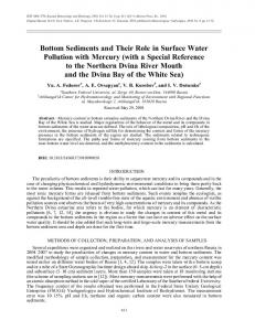
Based on results of numerical modeling, we obtained a scene of the general wave regime, which is shown in Figure 4 as isolines of significant wave heights. In addition, this picture also shows vectors characterized main directions of wave move.
Fig. 3. Isolines of significant wave heights
From picture 4 it is clearly visible that above underwater reefs there is a change in the height and direction of waves - their significant transformation takes place. This is due to changes in the depth, wave’s refraction and diffraction. Because of the collapse of waves and the dissipation of mechanical energy, the wave height in this space decreases. Results of calculating wave elements in the design point using numerical simulation are presented in Table 3. Table 3. Results of calculating wave elements in the design point using numerical simulation Wave formation direction NW
Vw, m/s 25
̅̅̅ ℎ 𝑑, m 2,54
̅̅̅ 𝑇𝑑 , s 5,79
̅̅̅ 𝜆𝑑 , m 54,89
Results of the numerical modeling were compared with results of calculation according to the normative document. Comparison of results shows differences in the wave height by more than 1,5 times. This is due to the simplified methodology for calculating elements of wind waves, given in the normative document, which does not accurately take into account the phenomenon of wave diffraction or the phenomenon of wave enveloping obstacles. The mean wave period and the mean wave length show also highly differences, what looks plausible.
5
MATEC Web of Conferences 251, 04048 (2018) IPICSE-2018
https://doi.org/10.1051/matecconf/201825104048
4 Discussion Comparison of results of modeling with results of calculation according to the normative document does not meet even the most modest requirements or standards: the calculated wave height is 1,5 times higher than the wave height obtained in the numerical modeling. When calculating by [1], sharp changes in the bottom relief, which largely affect the wave regime of the water area, are not taken into account. This leads to a significant overestimate of the calculated wave height for designed structures, and, consequently, to a significant rise in the cost of the structure. The conclusion can be expressed in the following way: when calculating marine hydraulic structures, the method of calculating wave conditions described in [1] can be used only at the stage of preliminary design. With further design for these purposes, it is necessary to resort to numerical and/or physical modeling, since this can help to save economize on cost of designed structures. It should be noted that similar methods of calculating wave elements should be carried out only by the absence of results of long-term observations of the wave regime in the water area. It is also necessary to say that any model (numerical and physical) first needs calibration and verification of obtained results with real observational data. If there is a lack of data in the water area, then it is necessary to resort to observations over water areas, which are similar to those in question. The difference in results obtained requires further study and detailed research. Perhaps, described feature should be given to taking into account in the calculation methodology described in the normative document. It follows from results of numerical modeling that the Bezymiannaya Bay is well protected from large height waves and can be used in the future for the development of maritime transport infrastructure. However, to confirm results of numerical simulation in this area, it is necessary to carry out physical modeling or live observations of wave conditions in the water area for at least one year.
References 1.
2.
3. 4.
5. 6. 7.
SP 38.13330.2012. Nagruzki i vozdeystviya na gidroteknicheskiye sooruzheniya (volnovykh, ledovykh i ot sudov) [Loads and impacts on hydrotekhnical structures (of waves, ice and boats)]. Moscow. (Minregion Rossii, 2011) (rus) D.D. Lappo, S.S. Strekalov, V.K. Zavyalov. Nagruzki i vozdeystviya na gidroteknicheskiye sooruzheniya [Loads and impacts on hydrotekhnical structures]. Leningrad. (VNIIG imeni Vedeneyeva, 1977) (rus) L.I. Lopatukhin. Vetrovoe volnenie [Wind waves]. Sankt-Petersburg. (SPbGU, 2012) (rus) I.G. Kantardgi, K.I. Kuznetsov. Naturniye izmereniya volneniya pri opredelenii nagruzok na morskie gidrotekhnicheskiye sooruzheniya [Measurements of waves during the determination of loads on marine hydraulic structures]. Magazine of Civil Engineering, 4 (2014) (rus) B.G. Galenin. Veter, volny I morskiye porty [Wind, waves and seaports]. Leningrad. (Gidrometeoizdat, 1986) (rus) I.G. Kantardgi, M.J. Zheleznyak. Laboratory and numerical study of waves in the port area. Magazine of Civil Engineering, 6 (2016) MIKE Powered by DHI [Electronic resource]. URL: https://www.mikepoweredbydhi.com/
6