Calibration of MHD Flowmeter Using COMSOL Software *S. Sahu1, R.P. Bhattacharyay1, E. Rajendrakumar1, E.Platacis2, I.Brucenis2 1 Institute for Plasma Research, Gandhinagar-382428, India 2 Institute of Physics, University of Latvia, Salaspils-2169, Latvia Institute for Plasma Research, Bhat, Gandhinagar, 382428, India; E-mail:
[email protected]
Keywords: Liquid metal, Nuclear reactors, Flow meter, Fluid Dynamics, Maxwell’s law
thermo-physical properties of the liquid metal, like electrical conductivity, viscosity as well as upon the resistivity of the process pipe. Hence, the flow meter calibrated at room temperature for a liquid metal will not behave the same for other liquid metal at another temperature. In other words, the flow meter has to be calibrated each time for a liquid metal and at required temperature. Numerical codes can be used to eliminate this repeated calibration work with different liquid metal and temperature. One way, is to validate the calibration data with numerical code for known liquid metal and temperature, then replace the properties of the liquid metal in the numerical code with required liquid metal and temperature, and obtain the calibration coefficient. In this paper, the calibration work of such a flow meter has been presented. At first, the flow meter was calibrated with Hg at room temperature using numerical code, and then the code was inserted with properties of Pb-Li at 350 oC, and the calibration coefficient for the flow meter with Pb-Li was estimated. The calibration data for Hg and Pb-Li obtained thorough numerical code are compared with that of experimental data.
1. Introduction:
2. MHD Flow meter description:
Liquid metals are the trenchant coolant in nuclear reactors. Liquid metals like Na, Na-K, Pb-Bi and Pb are used in Fission reactors [1]. Liquid metals like Pb-Li and Li are promising in fusion reactor applications [2]. These liquid metals have high melting point (100 oC – 350 oC). One of the major factors affecting the efficiency of the reactor is the coolant flow rate. Non-intrusive methods are essential for veracious flow-rate measurement. High temperature flow meters are not readily available and also come at a high price. An economic and precise way of non-intrusive flow measurement is to measure the emf developed in the liquid metal, when an external transverse magnetic field is applied [3]. Calibration is an important factor for flow meter utility. The emf developed in the above method depends upon the
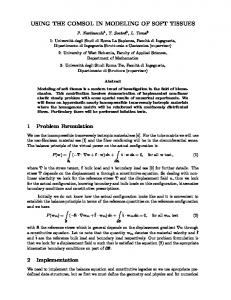
The flow meter consists of a ferromagnetic (Mild Steel) C section. The upper and lower half of the C section is fixed with permanent magnets as shown in Fig 1. Sm2Co17 magnet was used due to its high operating temperature and Curie point. This combined section is placed at the location of flow measurement, such that the applied magnetic field is transverse to the liquid metal flow direction. In the side wall of the pipe two pins are welded of the same material as that of the process pipe. Same material is chosen to avoid contact resistance due to dissimilar material. The underlying principle behind the flow meter is the motional emf developed due to the Lorentz force experienced by the charge particles in the liquid metal. The motional emf depends upon the flow rate of the liquid metal.
Abstract: There is limited option for non-intrusive flow measurement of liquid metals at high temperature. Liquid metal flowing in a conduit along with the transverse magnetic field induces emf in the liquid metal. The emf developed, which has linear dependency on flow velocity, can be used for flow velocity estimation. In case of conducting conduit the emf can be measured at the conduit wall. The main hindrance with this technique is the calibration. The induced emf depends upon the thermo-physical parameters like electrical conductivity, viscosity of the liquid metal as well as the electrical conductivity of the conduit wall. The flow meter calibrated with a fluid at some temperature will not behave in the same way with other liquid metal or at another temperature. Usage of flow meter with different fluid necessitates calibration with that fluid at required temperature; which increase the cost of usage. In this paper, an effort has been made, using numerical methods, to eliminate the repeated calibration work for different fluid at different temperature.
Excerpt from the Proceedings of the 2012 COMSOL Conference in Bangalore
Magnet
introduces the Lorentz force on the liquid metal due to the current induced in the liquid metal. (3)
SS pipe
Turbulent viscosity
SS pin
(4)
Mild steel Fig. 1: The schematic of the flow meter arrangement: the liquid metal flows into the plane of paper, the magnetic field is from top to bottom in the plane of paper and the potential pins are perpendicular to both the magnetic field and liquid metal flow direction.
Transport equation for turbulent kinetic energy (
((
)
)
(5)
Where the production term is (
(
The emf developed can be given by the relation E=KU
)
(
) )
(
) )
(1)
Where, U is the flow rate of the liquid metal. K is the calibration coefficient which is dependent on the applied magnetic field, effective length of the flow meter, pipe material and liquid metal. K remains constant for a given dimension, constant magnetic field, liquid metal and process pipe.
3. Use of COMSOL Multiphysics:
Transport equation for turbulence energy is
((
(
dissipation
rate
of
) ) )
(6)
The inbuilt constants used in the above equation are
COMSOL is a FEM based software capable of simulating most multiphysics problems [4, 5]. To simulate our problem a model with the same dimension as that of the flow meter is built in COMSOL. AC/DC module and CFD module are selected to work out our problem. Reynolds number for our case is about 30000. To simulate the turbulence phenomenon, the k- Turbulent model is used for the liquid metal flow. The liquid metal is considered to be incompressible and Newtonian.
C = 0.09, C1 = 1.44,C2= 1.92,
k=
1.0, = 1.3
The resultant velocity is fed in the Generalised Ohm’s Law. Maxwell equations along with the current conservation equation are used to take care of the magnetic field and induced current. The Lorentz force acting on the fluid is coupled with the Reynold’s average Navier Stokes equation for the velocity estimation, which is applied in the generalised Ohm’s Law to obtain the motional emf. Maxwell equations:
Equations used [5]: (7) The following equations are solved for the liquid metal flow to get the velocity profile as in pipe under transverse magnetic field. The Lorentz force acting on the liquid metal is estimated using Maxwell’s laws and Generalised Ohm’s Law.
(8) (9) (10)
Reynold’s averaged Navier Stokes equation (
)
(
Ampere’s law
)
(11) (
(
)
(2)
Excerpt from the Proceedings of the 2012 COMSOL Conference in Bangalore
Current conservation equation (12) Generalised Ohm’s law (
)
(13)
The equations (2)-(13) are solved simultaneously to obtain the emf developed in the pipe wall. All the notations used have their usual meaning.
near the liquid metal is such that it supports the flow near the wall and opposes at the centre of the pipe. This is due to the opposite direction of induced current at these locations. The Lorentz’s force contribution in the liquid metal is shown in Fig 3. Velocity Lorentz Force
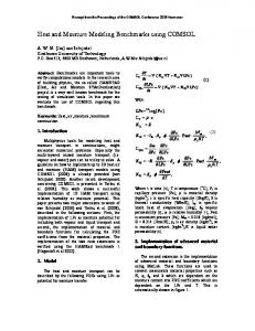
4. Analysis results: To gain confidence in the analysis result following checks were performed:1. Change in conductivity of liquid metal changed the emf developed at the pipe wall 2. Change in process pipe conductivity changed the emf developed at the pipe wall 3. The change in remnant magnetic field of magnets changed the magnetic field 4. Change in permeability of the Mild steel changed the emf developed at the pipe wall The above mentioned changes are obvious from the laws of physics. Movement of the liquid metal in the external magnetic field induces current in the liquid metal. The current induced has the opposite direction near the wall as compared at the centre of the pipe.The induced current across the liquid metal is shown in Fig 2.
Fig 3: Lorentz force is in the same direction of flow near the walls and opposite at the centre of the pipe.
The Lorentz’s force contribution to the liquid metal decreases the flow velocity at the centre of the pipe and increases the flow velocity near the wall. Hence, jet type flow is observed near the wall. As a result the M shaped flow profile is obtained across the side wall [6].The flow profile across the side wall is shown in Fig 4.
Fig. 2: Front view of the liquid metal section;the induced current in the liquid metal near the wall of the pipe has opposite direction as compared to that at the centre
This induced current acts with the external magnetic field to produce the J×B Lorentz’s force in the liquid metal. The Lorentz force contrubution
Fig.4: Velocity profile across the side wall, which resembles English alphabet M
Excerpt from the Proceedings of the 2012 COMSOL Conference in Bangalore
The emf induced in the pipe as well as the liquid metal when the liquid metal flows in the magnetic field is shown in Fig 5. Opposite potentials are generated at the side walls of the pipedue to the accumulation of electrons experiencing Lorentz’s force at one side wall and deficiency of electrons at the other wall.
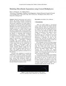
venturimeter. To simulate the calibration data, the model built in COMSOL is inserted with thermophysical properties of Hg and SS 316, and the emf developed in the pipe wall is computed for each flow rate [7]. The experimental and simulation calibration data for the flow meter with mercury at room temperature is shown in the Fig 6. COMSOL and experiment results differ at most by 7 %. Hence, the COMSOL model is validated for MHD flow meter calibration with Mercury. 4.(b) Calibration of flow meter with Pb-Li:
Fig. 5:Emf (in V) induced in liquid metal and the pipe.
The potential developed in the liquid metal and the wall of the pipe has linear dependency on the flow velocity. Hence, the side wall potential difference at the centre of the magnet arrangement is considered as the flow indicator. 4.(a) Calibration of flow meter with Mercury: The comparison technique is used to calibrate the flow meter with mercury. The flow meter is placed in a mercury loop, made up of SS 316, along with a venturimeter and an electromagnetic (EM pump) pump. The experiment is performed at room temperature.
MHD Flow meter is calibrated for Pb-Li with the help of a rectangular channel placed in a 4T magnetic field. Both the rectangular channel and the MHD flow meter are placed in a Pb-Li loop. PbLi is circulated in the loop using an electromagnetic pump. The rectangular channel and the loop are made up of SS 316 and the loop is operated at 350 oC. The rectangular channel is placed in 4T magnetic field such that the field is perpendicular to the Pb-Li flow. Estimation of the Pb-Li velocity in the channel is done through the measurement of wall electric potential and comparing it with analytical correlation [8]. The MHD flow meter is calibrated using the estimated flow rate in the rectangular channel [9]. To simulation the calibration data with PbLi, the COMSOL model validated for MHD flow meter calibration with Hg is inserted with the thermophysical properties of PbLi and SS 316 at 350 oC [10]. Then, the emf developed in the pipe wall is computed for different flow rates. The experimental and simulation calibration data is shown in Fig 7. The experimental and COMSOL result differs at most by 2 %.
Fig 6: The calibration result with mercury
Different flow rates are obtained by changing the rpm of the EM pump in the loop. The MHD flow meter is calibrated with the data obtained from
Fig 7: The calibration result with Pb-Li
Excerpt from the Proceedings of the 2012 COMSOL Conference in Bangalore
The calibration coefficient for the flowmeter was obtained by using equation (1) as follows
[2] Materials flow, recycle, and disposal for deuterium-tritium fusion; H.J. Willwnberg, T.J.Kabele, R.P.May and C.E.Willingham; PNL2830 (1978)
E is the emf developed and U is the flow rate.
[3] Flow measurement techniques in heavy liquid metals; T Schlenberg, R. Stieglitz; Nuclear Engineering and Design; 240 (2010) 2077-2087
4.(c) Estimation of calibration coefficient
The comparison of the experimental and the simulated calibration coefficient for the flow meter is shown in Table 1. Calibration factor
Experiment al (mV.s/cm3)
COMSOL result
Error (%)
(mV.s/cm3)
For Hg
0.0447
0.0418
6
For Pb-Li
0.0362
0.0357
2
Table 1: The comparison of calibration coefficient for the flow meter for Hg and Pb-Li.
The experimental and the COMSOL results match to a greater extent. Hence, the model validated for flow meter calibration at some temperature with known liquid meal can be used to get the calibration coefficient of the flow meter at other temperature and liquid metal. 5. Summary: A technique for high temperature liquid metal flow measurement has been proposed. The flow meter calibration at high temperature using COMSOL has been discussed. There is a fairly good agreement between the experimental and COMSOL results for the calibration coefficient. The usage of COMSOL reduces the cost of the repeated calibration work needed for the flow meter.
[4] Probe type permanent magnet flowmeter; V.Sharma, S.Narmadha, S.K.Dash, R.Verrasamy, B.K.Nashine, K.K.Ranjan, P.Kalyanasundaram; COMSOL conference 2010, India [5] AC/DC module and CFD module user manual; COMSOLmultiphysics 4.3 [6] Effect of magnetic field on MHD pressure drop inside a rectangular conducting duct; P. Bhuyan, K. Goswami; IEEE Transactions on plasma science, vol 36. No 4. August 2008,(1955-1959) [7] Thermo physical properties of materials for nuclear engineering, P. L.Kirillov, Institute for heat and mass transfer in nuclear power plants, Obninsk 2006 [8] A variational method of calculating magnetohydrodynamic flows in slotted channels with conducting walls; S.I.Sidorenkov and A.Ya. Shisko; MagnitnaGidrodinamika, Vol. 27, No4, pp. 87-99 oct-dec, 1991 [9] Calibration of MHD flowmeterin PbLi loop from the measurement of electric potentials on walls of the rectangular channel in a strong magnetic field,8th PAMIR International Conference on Fundamental and Applied MHD Borgo – Corsica - France September 5 - 9 , 2011 [10]Thermophysical properties of the Li(17)Pb(83) alloy; B.Schulz; Fusion Engineering and Design 14 (1991) 199-205
Acknowledgement: One of the authors is thankful to Mr. V. Sharma, IGCAR, Kalpakam for the precious discussion and help. References: [1] Design study of Pb-Bi and NaK cooled small deep sea fast reactors; A. Otsubo, M. Takahashi Progress in nuclear energy; Volume 47, Issues 1– 4, (2005) 202–211
Excerpt from the Proceedings of the 2012 COMSOL Conference in Bangalore