Camera Augmented Mobile C-Arm Towards Real Patient Study Lejing Wang1 , Simon Weidert2 , Joerg Traub1 , Sandro Michael Heining2 , Christian Riquarts2 , Ekkehard Euler2 , Nassir Navab1 1
Chair for Computer Aided Medical Procedures (CAMP), TU Munich, Germany 2 Trauma Surgery Department, Klinikum Innenstadt, LMU Munich, Germany
[email protected]
Abstract. The Camera Augmented Mobile C-arm (CamC) system that extends a regular mobile C-arm by a video camera provides an X-ray and video image overlay. Thanks to the mirror construction and one time calibration of the device, the acquired X-ray images are co-registered with the video images without any calibration or registration during the intervention. It is very important to quantify and qualify the system before its introduction into the OR. In this communication, we extended the previously performed overlay accuracy analysis of the CamC system by another clinically important parameter, the applied radiation dose for the patient. Since the mirror of the CamC system will absorb and scatter radiation, we introduce a method for estimating the correct applied dose by using an independent dose measurement device. The results show that the mirror absorbs and scatters 39% of X-ray radiation.
1
Introduction
Mobile C-arms are an everyday tool to acquire X-ray images in the operating room during surgery. The Camera Augmented Mobile C-arm (CamC) system that extends a regular mobile C-arm by a video camera was proposed by Navab et al. [1] for X-ray and video image overlay. Thanks to the mirror construction and one time calibration of the device, the acquired X-ray images are co-registered with the video images without any further calibration or registration during the intervention. The CamC system can support a wide range of potential clinical applications, such as needle guidance [2], interlocking of intramedullary nails [3], and pedicle screw placement [4]. However, it is very important to quantify and qualify the system before its introduction into the operating room for the real patient study. Every clinically used mobile C-arm has a dose-area product (DAP) meter permanently built into the x-ray tube housing to measure the radiation dose to air. The overall measured DAP values must be recorded for each patient, and these DAP values allow to determine the patient exposition and eventually the effective dose which is related to the cancer risk of the procedure [5]. However, one mirror of the CamC system is placed between the DAP meter and the patient. Thus, it is partially absorbing and scattering radiation, and the patient will receive less dose than the reading from the built-in DAP meter. Both
98
Wang et al.
the accuracy of the video and X-ray image overlay and the correct applied dose to the patient by using the CamC system are clinically important parameters. Therefore, we extended the performed overlay accuracy analysis of the CamC system by the evaluation of the percentage of absorbed and scattered radiation of the mirror. This value can be then used to estimate the correct applied dose to the patient.
2
Materials
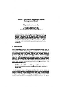
Our Camera Augmented Mobile C-arm system is composed of a mobile C-arm, Siremobile Iso-C 3D, from Siemens Healthcare and an optical video camera, Flea, from Point Grey Research Inc. A double mirror construction is attached to the housing of the X-ray source to virtually align the camera center with the X-ray source. Figure 1 shows the system setup of our dose evaluation experiments. One standard mirror of the CamC system is placed between the built-in DAP meter and the image intensifier. For evaluation of the applied radiation dose for the patient, we employed an independent dose measurement device (see figure 1), which consists of the Unfors Xi R/F Detector and the Unfors Xi Base Unit, from Unfors Instruments GmbH, Germany. The Unfors Xi R/F Detector can measure the X-ray radiation dose in the range from 10 nGy - 9999 Gy with the uncertainty of 5%. This detector is connected to the Unfors Xi Base Unit which displays and records the measured results. It is used to evaluate the percentage of absorbed and scattered radiation by the mirror.
Fig. 1. The left shows the CamC system, the right top is the built-in DAP meter, and the right bottom shows our dose measurement device (Unfors Xi).
Camera augmented mobile C-arm
3
99
Evaluation
To determine the accuracy of the image overlay for the guidance of medical instruments using CamC, we performed a set of experiments to compute the difference of corresponding feature points between the video image and the overlaid X-ray image. Futhermore, to determine the correct applied dose to the patient, we introduced a method by using an independent dose measurement device for finding the percentage of absorbed and scattered radiation by the mirror. This value will eventually allow to correct the values given by the built-in DAP meter. 3.1
Overlay accuracy
We performed the experiments to evaluate not only the accuracy of the image overlay for the instrument guidance, but also the influence of the orbital and angular rotation on the overlay accuracy. A pattern that is generally used for geometrical X-ray calibration and distortion measurements is attached to the image intensifier. The markers of the pattern are visible in both X-ray and video image at the same time. The centroids of the markers are extracted in both views with subpixel accuracy and used to compute the overlay error which is the distance between corresponding point pairs. We performed the proposed calibration of [1] and then computed the difference of the centroid in the video image and overlaid X-ray image. The mean error was found to be 1.59 ± 0.87 pixels with a maximum error of 5.02 pixels. The same experiment with the attached calibration phantom was also conducted with different angular and orbital rotations. In all angular and orbital poses we analysed the overlay accuracy with and without an online estimation of a new homography. The mean overlay error was found to be constant during orbital and angular rotation of the C-arm if a re-estimation of the homography is performed at the specific C-arm orientation. In the cases where the homography was not re-estimated, i.e. the homography was estimated in the original position of the C-arm with no orbital and angular rotation and applied for other poses of the C-arm, the mean error of the points increased with an increase in the rotation angle. 3.2
Dose estimation
Since the Unfors Xi R/F Detector can not intercept the entire area of the X-ray beam on any plane perpendicular to the beam central axis between the X-ray housing and the image intensifier, we can not directly measure the total dose. Thus, the property of the dose distribution on the plane has to be known to derive the total dose in our case. Generally, the dose distribution of the C-arm Cone-Beam on the plane perpendicular to the beam central axis is homogenous. However, we conducted an experiment to check the dose distribution in both cases of with mirror and without mirror. We placed the dosimeter, Unfors Xi R/F Detector, on the image intensifier in three different positions. For each of the three positions (see figure 2), we took 3 shots with the mirror and another 3 shots without the mirror. Through the whole experiment, we used the single shot
100
Wang et al.
Table 1. The measured dose(µGy) of each shot by the Unfors Xi R/F Detector with the fixed tube voltage(64 kV). Mirror
position A
position B
position C
Mean±std
Without 27.04 25.82 25.85 26.00 26.00 26.25 26.54 26.05 26.17 26.1911 ± 0.3862 With 15.36 14.41 15.71 14.93 16.06 16.00 15.46 15.62 15.08 15.4033 ± 0.5302 Table 2. The average measured dose (µGy) for three different tube voltage settings, 64 kV, 70 kV and 77 kV. Rate refers to ”Percentage of absorbed and scattered radiation”. Mirror Without With Rate
64 kV (Mean±std)
70 kV (Mean±std)
77 kV (Mean±std)
26.0833 ± 0.1443 15.6633 ± 0.6358 39.95%
33.6200 ± 0.1572 20.5467 ± 0.3656 38.89%
96.6167 ± 0.5369 60.1967 ± 1.7923 37.70%
mode (DR-mode) with fixed radiation time and the tube voltage (64 kV) in order to produce constant radiation doses for each shot on the level of the x-ray tube. The dose values measured by the unfors dosimeter are shown in Table 1. For each case, the standard deviation is relatively small. This means dose distribution on the detector level is homogenous with and without the mirror. Therefore, the percentage of the absorbed and scattered radiation estimated for the partial area of the X-ray beam corresponds to the entire X-ray beam. In order to investigate the influence of the tube voltage on the percentage of absorbed and scattered radiation, we performed another experiment. In this experiment, we used the DR-mode of the C-arm and a fixed dosimeter position (Position B) for all shots. In each of the three different tube voltage settings, 64 kV, 70 kV and 77 kV, we took 5 shots with mirror and another 5 shots without mirror. Table 2 shows the average dose values for each case. The percentage of absorbed and scattered radiation by the mirror was found to be almost constant for the different tube voltage settings. Knowing the total applied dose (DAP) from the C-arm’s built-in DAP meter, we can apply 39% as the percentage of the absorbed and scattered radiation by the mirror to estimate the correct applied dose for the patient according to our experiments.
Fig. 2. The positions of the Unfors Xi R/F Detector in our experiments. From the left to the right, they are position A, position B and position C.
Camera augmented mobile C-arm
4
101
Discussion and conclusion
The CamC system proposed by Navab et al. [1] can support a wide range of potential clinical applications as shown by their cadaver studies of [2], [3] and [4]. Since the mirror of the CamC system will absorb and scatter radiation, the applied dose (DAP) from the C-arm is on longer valid for the patient. Before the introduction of the CamC system in the OR for patient studies, it is required to quantify and qualify the system not only for the technical accuracy, but also for the correct applied dose to the patient and estimation of the scattered radiation. In this paper, we extended the previously performed overlay accuracy analysis by estimating the percentage of the absorbed and scattered radiation by the mirror. The results show that the mirror absorbs and scatters 39% of X-ray radiation. The applied dose was adjusted such that the dose with the mirror construction matches the dose without the mirrors resulting in no change of the X-ray image quality. The housing of the radiation source was covered by lead foil to reduce the effect of scattered radiation for surgical staff. To correct the overlay after a deviation of the C-arm from the calibrated orientation (e.g. gravity effects on C-arm structure), we will adapt the idea of a virtual detector plane proposed by [6] and attach at least four X-ray markers on the back of the mirror. Last but not least, an X-ray and video visible marker is employed for patient motion detection since the overlay will not be valid if the patient and the C-arm have a relative motion. In case the marker in the X-ray image and the video image are not aligned, a new X-ray image must be acquired. The CamC system provides a promising solution for image guided surgery which could lead to a considerable reduction of radiation dose for patients and surgical staff in the future. Acknowledgement. Thank to Unfors for providing the dose measurement device.
References 1. Navab N, Mitschke M, Bani-Hashemi A. Merging visible and invisible: Two cameraaugmented mobile C-arm (CAMC) applications. Procs IWAR. 1999; p. 134–141. 2. Mitschke M, Banihashemi AH, Navab N. Interventions under video-augmented x-ray guidance: Application to needle placement. Procs MICCAI. 2000. 3. Heining SMM, Wiesner S, Euler E, et al. Locking of intramedullary nails under video-augmented flouroscopic control: First clinical application in a cadaver study. Proc CAOS. 2006. 4. Heining SM, Wiesner S, Euler E, et al. Pedicle screw placement under videoaugmented fluoroscopic control: First clinical application in a cadaver study. Int J Computer Assist Radiol Surg. 2006;1(Supplement 1):189–190. 5. Schultz FW, Zoetelief J. Dose conversion coefficients for interventional procedures. Radiat Prot Dosimetry. 2006;117(6):225–230. 6. Navab N, Mitschke M. Method and apparatus using a virtual detector for threedimensional reconstruction form x-ray images. Patent US 6236704.