Design of Clocked Circuits Using UML Zhenxin Sun, Weng-Fai Wong, Yongxin Zhu
Santhosh Kumar Pilakkat
School of Computing National University of Singapore E-mail: {sunzhenx, wongwf, zhuyx}@comp.nus.edu.sg
Embedded Systems-SDR Lab Institute for Infocomm Research, Singapore E-mail:
[email protected]
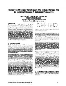
Abstract – Clocking is an essential component of any embedded system design. However, traditional design techniques are either short of clocking support or too complex for users. The Unified Modeling Language (UML) has been proposed as design tool in real time system design, but the clocking semantics has not been properly dealt with. In this paper, we will present our experience of using UML to design a clocked system. In particular, UML is used to model the digital down converter, an essential component of software radios. Our tool chain automatically generates the simulation as well as synthesizes the final implementation.
I. INTRODUCTION With the increasing complexities of embedded systems, designers have been searching for new methodologies that can manage the complexity as well as yielding high productivity.[2] The Unified Modeling Language (UML) is a proven modeling and specification language that has been used widely in development of complex software applications [13]. However, UML lacks natural support for timing semantics. Previous works have tried to use extra notations to specify the clock settings. Most of these notations are not interchangeable and non-reusable. In this paper, we address this problem by showing how we can use existing UML notations to specify a real time system with clock settings. This design is then automatically translated into detailed implementations that include simulators as well as synthesized hardware. In our framework, UML’s class and component diagrams, as well as statecharts are translated into an intermediate form in SystemC. Clock settings are used during the SystemC code generation. At the end of this top-down design flow, synthesizable SystemC models are generated. Therefore, very high level specifications can be lowered to implementations that are very close to hardware [11]. Structure
Behavior
Clocking
SystemC implementations from the model.
II. RELATED WORKS AND SCOPE OF OUR WORK Lack of support for clocks is a challenge for the several efforts similar to ours that use UML as the design vehicle. In YAML[10], the system structure is modeled using UML notions with extensions. Some results have been reported using both class diagram and statechart to generate SoC designs without clock specifications [3,4,12]. In another approach, extended task graphs were used to capture the system’s behavior as well as the clock specification [5]. Our approach differs from others in that rather than formulating another system description language, we used standard UML for the task. In particular, we use I-logix’s Rhapsody to build UML models and specify clock setting in the component diagrams. The following features are unique in our approach: 1. To ensure the correctness and reusability, we use the existing UML notations available in Rhapsody 4.2 with customization to build executable UML models. 2. Clock settings of components are specified using component diagram. They are used in the code generation phase. 3. XMI, an interchangeable UML representation, is used as the input of our translator which then generates SystemC code directly. 4. The generated SystemC models can be simulated using the SystemC simulator, and the implementation can then be easily tested and verified. Specifications
UML
XMI Refinement TLM model
Class Diagram
Statechart Diagram
Component Diagram
Behavioral model
Synthesis Gate model
Translator
RTL model
System Level Implementation
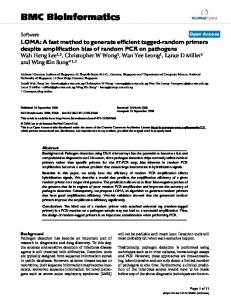
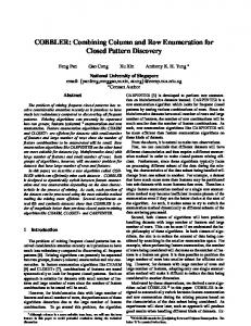
Figure 2 UML to SoC design flow Figure 1 Our Design Flow of the Clocked Chips
Figure 1 shows our design flow. We start` with formal UML models, specifying different aspects and requirements of the system using different UML diagrams. All these diagrams are used as input to the translator. The translator automatically generates the system level
Figure 2 shows the proposed code generation flow. Starting with the system’s specification, UML models are built. Verification and refinement can be done at several levels to test whether the requirements are completely and correctly captured. The system is first translated into transaction level modeling (TLM) level model. This can be
done fairly rapidly. When there is sufficient confidence obtained from simulation, the behavioral and RTL level models can be generated. These can be further compiled into gate level models. In this top-down flow, testing and verification can be done at all the stages. The controlled lowering of the model with extensive testing at every stage is essential for the successful design and deployment of complex embedded solutions.
III: IMPLEMENTATION OF DESIGN FLOW Our design flow is based on UML notations and SystemC. In the design flow, designers only need to work at the UML level and the rest are automated, thereby boosting productivity. In rest of this section, we will introduce the details of how we capture the system specification and SystemC code generation. Class Diagram Semantics and Translation: Class diagrams are used to model the structural information of a design.[7] Classes are used to model the system components and communication interfaces. A class has attributes and operations. Each attribute has a type, publicity and static status. Functions have return types, arguments types and names, as well as the publicity and static status. Each class will be translated into a SystemC sc_module. To model different module elements, we make use of the stereotype of class. There is a mapping from SystemC elements to the UML stereotypes. To model the details of the SystemC design elements, we introduced three extensions using UML stereotypes mechanism. Table 1 shows the mapping between SystemC elements and UML stereotypes. SystemC elements Modules Interfaces Primitive channel Hierarchical channel
UML stereotypes Normal class
Table 1 Mapping from SystemC elements to UML stereotypes
Aggregation is used to model the ‘contains’ information of components. If A has aggregation relation with B, then B will be modeled as component of A. Associations among the classes are used to model the communication relationships between the components. These relations include association and aggregations. If two components have message or signal exchange, an association will be placed in between. The direction of the association indicates the direction of the communication. Statechart and Component behaviors: The statechart formalism was introduced by Harel [1]. A statechart design essentially consists of states and transitions like a finite automaton. Statechart diagrams in UML allow for guards on transitions, propagated transitions, actions on transitions, actions on state entry, activities that last as long as a states, and actions on exit. Figure 3 shows an example of a statechart consisting of a simple state and an initial state.
Dynamic behavior of a UML class is expressed in terms of state transition diagrams of simple states which in turn is translated as a process. SystemC provide three different types of processes: sc_thread, sc_cthread, and sc_method, which we use in different levels of abstraction[8]. A local variable called a state is used to hold the current state identifier, and it is assigned to the value of initial state identifier during the initialization stage. Processes keep transiting between states until a final state is reached. When the process enters a new state, it first performs the actions_on_entry. Then the reaction is performed. For most of time, processes stay in one state, waiting for some events. Upon receiving an event, a process will perform the guard action and change the value of state accordingly. When it exits the state, the action_on_exit will be performed. State transitions are translated into variable assignments to states in main loop. Each transition corresponds to assigning a new state identifier to the state variable. The assignment will be done after the action_on_exit actions are performed. datain/ if(N