Schedulability Analysis of Messages in a CAN Network Applied to an Unmanned Airship Max Mauro Dias Santos* , Marcelo Ricardo Stemmer**
Francisco Vasques
Department of Production and Systems Engineering* Department of Automation and Systems** Federal University of Santa Catarina, BRAZIL
[email protected],
[email protected]
Department of Mechanical Engineering University of Porto PORTUGAL
[email protected]
Abstract - This paper presents the application of a CAN network to the integration of sensors and actuators in an unmanned airship called HELIX, based on the architecture of distributed processing proposed by [4]. Initially, a study of the viability of several communication networks used in vehicles (such as CAN, VAN, C2D and FIP, etc.) was accomplished [6]. The preliminary study concluded that the behavior of CAN was better for this application when compared to other types of networks analyzed. In the present work, a detailed study of the employability of a CAN network in the HELIX project was accomplished, including situations not considered in the preliminary analysis, such as the presence of Jitter in the group of messages, the high load of messages over the network, and the consideration of presence of transmission errors. As the CAN networks offers good properties for transmission of messages with temporal requirements, a schedulability analysis was accomplished for the transmission of messages and a numeric example is presented in an illustrative way to the present problem.
I. INTRODUCTION The control of vehicular systems such as automobiles, airships, space ships and trains, is generally accomplished by a set of sensors, actuators and processing units. Initially the control of such vehicles used to be conceived as a centralized system, in agreement with the existent technological limitations. With the evolution of the microprocessors and of the network communication systems, the philosophy of distributed processing took a prominence place in function of the processing capability, safety and reliability. The modern embedded systems in vehicles are distributed and the processing is accomplished by a set of sensors and actuators that communicate through a network. The distributed and networked control systems have three important characteristics when compared to centralized ones: a) volume reduction; b) weight reduction and c) increased processing capability. In the present work we will discuss the networked control of an unmanned airship, the helicopter HELIX [6],
conceived and projected by the Gyron Company [7]. This application has hard real time communication constrains. The HELIX control system was initially projected with a centralized processing, and in [6] a distributed processing proposal was presented, in function of the advantages that this architecture possesses [1]. In [6], a viability study of several networks existent in the market, such as VAN, CAN and FIP, among others, was accomplished. CAN [8] provided a better performance. CAN (Controller Area Network) was originally projected by BOSCH, with the objective of satisfying the requirements of electronic systems in automotive control systems. In this work, a detailed study of the use of CAN in the HELIX airship, considering conditions of Jitter on the messages, overload and noises on the net (aspects that were not considered in previous works), was accomplished. The following section describes the HELIX project. Section 3 presents a distributed architecture model for HELIX. Section 4 describes the main characteristics of CAN, as well as its temporal properties under conditions of normal operation and under errors. Section 5 shows the application of CAN to the HELIX system, and some numeric results are presented. Section 6 describes a general conclusion of the accomplished study. II. THE UNMANNED HELICOPTER HELIX In 1991, after the accomplishment of deepened studies and market estimates on RPVs (Remotely Piloted Vehicles), GYRON began the development of an aerial robot, which received the denomination of Project HELIX. The HELIX project consisted of an unmanned helicopter, a control station on earth and a support vehicle with capacity to transport up to 2 airships. The helicopter was conceived to accomplish tasks in that the human being took life risk, such as, inspection of transmission lines, surveillance of fire in forests, analysis of metallic structures, among others.
* lecturer at UNILESTE, PhD student at UFSC with a scholarship from FGPA.
1
Position sensor
Rotation sensor micro control. A
Payload
UpLink
LINK
Transputer
LINK
micro control. B
Fuel sensor
PWM Generator
DownLink Earth control station
Altitude sensor
Inertial sensors
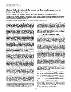
Figure 1: Communication between the helicopter and the control station on earth
It has a capacity to drive useful loads of up to 5 kg. The basic model transports a video camera for the transmission of images in real time, and a communication system among the control station on earth and the airship was accomplished through a radio frequency system, as can be seen in Figure 1. The original control system of HELIX consisted of a point-to-point architecture for the interconnection of sensors, actuators and control modules, with the objectives of monitoring and control of the airship. The necessary intra-vehicle data in the system HELIX is classified in three different types, in agreement with its functionality: a) data for the control of the airship; b) data for monitoring objectives; and c) data related to the application, including to the embarked camera and eventual additional sensors.
Controller - Flow control - PWM signals - Navigation
f1, f4, ..., f9
Inertial - Angular speed - Angular acceleration
f2, f3
f3, f5, ..., f9
f9
f1
RFLinks - References - Telemetry - Operation codes
Attitude sensors Motor Temper. Sensor
watchdog
Attitude - Angles
RF Link UpLink DownLink
Figure 2: Original processing structure of HELIX
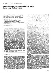
The initial point-to-point architecture was composed of 2 RISC microprocessors and a transputer [6] with a totally centralized processing, as can be seen in Figure 2. III. THE DISTRIBUTED REAL TIME ARCHITECTURE In [6] a distributed computation model for the HELIX system was proposed, using a diffusion network and supporting bi-directional communication. The proposed distributed architecture is shown in the Figure 3, with the respective details of the tasks and messages.
Position - Latitude - Longitude - Altitude - Linear speed
f6
f8
Battery charge sensor
f5, f7
Monitoring - Motor temperature - Battery charge - Fuel
Actuators - Receive PWM signals and execute
f2
Bus f4
Camera - Digital image
Figure 3: A distributed architecture for the HELIX system
2
In figure 3 the messages exchanged among the nodes are represented by fi, with i identifying the message. A detailed description of each message being transmitted is presented ahead. The study described in [6] was accomplished considering different network technologies used in automotive systems and industrial automation, such as: a) CAN; b) FIP; c) VAN; d) J1850; e) MIL-STD-1553B; f) C2D and g) CSMA/DCR. The above-mentioned study concluded that CAN was the best solution for the application in focus. In the present work, the usage of CAN is assumed as a project decision and the temporal behavior of the network is analyzed in more detail. IV. TEMPORAL ANALYSIS OF CAN An analysis of the latency of messages is presented in the worst case for messages in real time, which is similar to the analysis made in [2]. Some modifications have been considered: the deadline of a message (Dm) should not be larger than the period (Tm) and the bus controller should not transmit a message of low priority if exists a high priority message pending. CAN adopts a MAC (Medium Access Control) protocol known as CSMA/NBA (Carrier Sense Multiple Access with Non-destructive Bit-wise Arbitration). The Nondestructive bit-wise arbitration allows 100% utilization and message priority based on an 11-bit packet identifier. In this protocol, any node can access the bus when it is silent. Similar to Ethernet, each node attempts to transmit when the bus is free. Unlike Ethernet, there is no collision. If two or more nodes start transmitting simultaneously, bus conflict is resolved by bit-wise arbitration using the IDENTIFIER field. A “0” is dominant on wire and overrides a “1”. When a node transmits a “1”, but hears a “0”, it immediately stops transmitting. The “winning” node continues to transmit its message to completion. This mechanism guarantees that neither information nor time is lost. The value of the IDENTIFIER defines priority during arbitration (lowest IDENTIFIER “wins” arbitration). This means two nodes cannot share the same IDENTIFIER. All nodes check the consistency of the message being received and will acknowledge a consistent message and flag an inconsistent message in the ACK slot. CAN provides automatic error detection, signaling, and retries. The data portion of packet can be 0 to 8 bytes long. The CAN network operates with a fixed priority scheduling policy, but does not support pre-emption of messages.
A. Analysis of CAN response time According to [1], the transmission time of a message m in the worst case is given by: Rm = J m + wm + Cm
[1]
The term Cm represents the biggest time required to transmit a message m over the physical bus. The CAN frame contains 47 bits of overhead and a bit-stuffing width of 5 bits. Only 34 of the 47 bits suffer stuffing. The equation that represents Cm is: 34 + 8sm + 47 + 8sm τ bit Cm = 5
[2]
The term Sm indicates the size of the message m in bytes and the term τbit is the time spent to transmit a bit over the bus (for the 1Mbps bus we would have 1µs). The term wm represents the delay in the queue in the worst case (the biggest time spent between putting a message in a priority ordered queue and the beginning of the transmission) and is given by: wm = Bm +
wm + J j + τ bit C j Tj ∀j∈hp (m )
∑
[3]
The term Bm is the blocking time in the worst case of the message m and is given by: Bm = max (Ck ) ∀k ∈lp ( m )
[4]
where lp(m) is the set of messages in the system with lower priority than message m. The term Jj is the Jitter and Tj is the period of the set of messages with higher priority than message m. Since the term wm appears in both sides of the equation, a recurrent solutions is required, as shown bellow: wmn +1 = Bm +
wmn + J j + τ bit C j Tj ∀j∈hp ( m )
∑
[5]
Finally, the term Jm represents the message Jitter (average waiting time of the message at the transmission queue before scheduling) and is empirically determined. In the present work we use the value 0.1 ms. B. Analysis of CAN response time under error conditions Ken Tindell and Allan Burns [1] proposed a model for the calculation of the worst-case response time of messages in CAN under error conditions. The response time can be calculated as: Rm = J m + qm + Cm
[6]
The terms Jm and Cm have the same meanings as in the previous section. The term qm corresponds to the time spent by a message in the waiting queue under error conditions
V. APPLICATION OF CAN TO THE HELIX AIRSHIP
and is given by the following recurrent equation: qmn +1 = Bm +
q + J j + τ bit C j + Em (qm + Cm ) Tj ∀j∈hp ( m )
∑
n m
[7]
Em(t) is a function of the error recovery overhead and gives the superior limit of all error recovery overheads that can occur in a time interval t. It is given by the following equation: t Em (t ) = nerror + max (Ck ) − 1 29 + ∀k∈hp ( m ) ∪{m} Terror
[8]
where nerror is the number of errors that can occur in a small arbitrary interval and Terror is the period of error occurrence. The number of errors in an interval o duration t is given by: t nerror + −1 Terror
[9]
In every error, the error recovery overhead can be increased in 29 bits, followed by a message retransmission. Only messages with higher priority than message m can be retransmitted and cause a delay in message m. The biggest of those messages is: max
[10]
(Ck )
∀k ∈hp ( m ) ∪{m}
In the following sections, the equations above will be used in a schedulability analysis of CAN applied to the unmanned helicopter HELIX, considering the conditions of messages with Jitter, presence of error and a very elevated message load in the net.
#
Signal Description
1 2 3 4 5 6 7 8 9 10 11 12 13
PWM signals for servos s0 to s7 Angular acceleration Angular speed Position references Xref, Yref, Zref and Href Swashplate motor rotation (yaw) angle and its derivate Operation codes Linear speed (x, y and z) VDC, motor temperature Latitude, longitude and altitude (x, y, z) Adjustment Reference Telemetry e monitoring Digitalized Signal from camera
Size [bits] 8 x 16 3 x 16 2 x 32 4 x 48 1 x 16 2 x 32 3 x 48 3 x 48 3 x16 3 x 48 4 x 48 24 x 48 640
A. Model of Tasks and Messages The HELIX control structure is decomposed in 8 different subsystems: Controller, Inertial, Position, Actuators, RF-Links, Attitude, Monitoring and Camera. Each one includes a group of real time message generating tasks. The main temporal properties of the messages generated in the HELIX system are presented in Table 1, where T is the period, D is the deadline and P/S stands for Periodic/Sporadic. In relation to Jitter, we will consider that it is totally dependent of the latency of the application. The latency is the maximum elapsed time between the moment an application task asks for the transmission of a message and the placement of the message in the transmission buffer. We can consider a Jitter of 1ms for any flow of messages, because 1ms