Candidate Subcircuits For Functional Module Identification In Logic Circuits Travis E. Doom † Department of Computer Science and Engineering Wright State University
Jennifer L. White, Anthony S. Wojcik, Moon-Jung Chung ∗ Department of Computer Science and Engineering Michigan State University
ABSTRACT Recovering functional information from existing hardware is a difficult problem in design automation. However, it is an important focus for designers attempting to redesign for expanded functionality or superior performance. Often, the only reliable information available about a piece of digital hardware is the hardware itself. Documentation, even if it is available, may be outdated or incorrect. Existing procedures are able to recover the transistor-level netlist, or a gate-level netlist from an existing implementation. The next step in this process is the gate-level to module-level transformation, the focus of this paper. We have designed a technique to enumerate all of the potential modules within a gate-level netlist so that their functional equivalence to known modules may be evaluated.
1
INTRODUCTION
Reverse engineering of digital systems is an increasingly important area of study. The Air Force would like to recover the designs of obsolete ICs to extend the useful lifetimes of airplanes and weapon systems [13]. High-technology companies are attempting to reverse engineer products both to prevent copyright infringement and to maintain their competitive edge. Hardware designers are recovering designs to facilitate their re-implementation in superior technology. Government agencies world-wide are performing reverse engineering to keep apprised of the military capabilities of rival countries. Reverse engineering of digital system is a complex task, integrating tools from all areas of computer engineering to raise the level of abstraction from a circuit implemented in transistors to a more understandable module-level description. A transistor-level netlist is comprehensible to only the most experienced designers, but a module-level description, composed of functional modules such as ALUs, adders, and multiplexors, can be more easily understood. The transformation from the transistor-level to the gate-level has been addressed [2,9], but the gate-level to module-level transformation is considered an open problem in computer engineering. The goal of the work presented here is to develop techniques to solve this problem. The identification of modules in a netlist can be approached in one of two ways: syntactically or semantically. The syntactic approach searches through the netlist identifying all of the gate clus∗ †
{white,wojcik,chung}@cse.msu.edu
[email protected]
ters that are structurally identical to the known modules. Algorithms have been designed to efficiently perform syntactic matching in circuits [11] and the underlying problem of graph isomorphism has been investigated in depth within the graph theory community [8]. Unfortunately, not all functionally equivalent modules are structurally equivalent. Even with extensive libraries, it is unlikely that all structural representations of a functional module will be present. A more robust matching technique is semantic matching, which defines equivalence of modules by their functionality rather than their structure. This approach is a more powerful matching technique, but it is also more computationally complex.
2
STATEMENT OF PROBLEM
The general problem is stated as follows: Module Identification Problem [4, 5]. Given a gate-level logic circuit description (netlist), efficiently identify all gate clusters (subcircuits) that perform the function of a known standard library module. Our approach to the Module Identification Problem consists of solving two subproblems: • Candidate Subcircuit Enumeration Problem. Identification of clusters of gates (candidate subcircuits) within the netlist that may comprise a functional module. • Subcircuit Identification Problem. Proving functional equivalence between a candidate subcircuit and a known standard library module. To effectively locate the modules within a circuit, we first enumerate the candidate subcircuits. Candidate subcircuits are those subgraphs that are likely to have functionality that corresponds to a high-level module. Each of these subcircuits is passed to a semantic equivalence checker, which then functionally compares the subcircuit to any known modules that it may represent. Two combinational circuits are semantically equivalent if input and output correspondences exist under which their functionality is equivalent. It is possible to determine semantic equivalence between a subcircuit and a known module in a tractable number of comparisons. Fundamentally, semantic equivalence checking is the determination of equivalence between a pair of Boolean functions. This is a complex problem for arbitrary functions because of the difficulty of determining the input correspondence between the functions. Traditionally, this has involved testing each possible correspondence, an operation of factorial complexity.
Doom, et al [4] present a technique that applies signature functions to the functions of the subcircuits to determine their signature class. A signature function takes a function as input and returns a signature for that function. This signature is related only to the function itself; changeable features, such as variable ordering and labeling, do not affect the signature. All functions with a specific signature are grouped into a signature class. Only subcircuits within the same signature class can be equivalent, thus significantly reducing the number of comparisons necessary to determine equivalence. This technique has proven to be a reasonable solution to the Subcircuit Identification Problem. The research reported here hopes to provide a complete solution to the general problem by addressing the remaining Subcircuit Enumeration Problem.
the complexity of the enumeration can be significantly reduced by exploiting the fact that only some subgraphs are of interest in this domain. Consider a subgraph H composed of a gate vertex v and two vertices representing two of its three inputs (either gates or primary inputs). The vertex v does not represent a complete gate in the context of the subgraph H, because it is missing an input. For the purposes of module identification the process is greatly simplified by enumerating only those subgraphs that exclusively contain vertices representing fully specified gates; these subgraphs are referred to as subcircuits. This definition has also been independently developed and presented as feasible subgraphs [6]. A fully specified vertex represents a gate that is joined within the subgraph by either all of the vertices representing its inputs or none of those vertices.
3
Definition 4.1 In a subgraph H of a circuit graph G, a vertex v is a fully specified vertex if (∀u | uv ∈ E(G) ∧ u ∈ V (H)) ∨ (∀u | uv ∈ E(G) ∧ u 6∈ V (H)).
RELATED WORK
The syntactic matching technique has been extensively studied, most prominently in the area of transistor-level to gate-level transformation [2, 9]. This technique is particularly effective in that domain because the number of implementations for a gate, barring intentional obfuscation, is relatively small. Therefore, it is conceivable to have a library that contains all reasonable implementations of, for example, an AND gate, allowing all AND gates in the netlist to be located. Syntactic matching has also proven to be a useful tool for locating modules in gate-level to module-level transformations, particularly in netlists created by CAD tools, because they tend to use stock implementations of modules which are “plugged in” to the design. In addition, designers tend to use published or textbook designs for their modules [7]. These modules, if an implementation library is available or can be created, can be located by using subgraph isomorphism techniques [11] or pattern matching techniques [7, 12]. The syntactic technique is very effective when details about the implementation of the modules are available. Unfortunately, that is seldom the case. To solve the more general problem of module identification, semantic matching is required. A similar semantic approach to the Module Identification Problem is being explored at Argonne National Laboratory. Chisholm, et al [3] believe that more significant algorithmic improvement is possible by improving the approach to Subcircuit Identification. We feel that the performance enhancement gained by reducing the applications of Subcircuit Identification is equally significant.
4
CANDIDATE SUBCIRCUIT ENUMERATION
It is necessary to consider all subgraphs for possible functional equivalence to known modules to ensure that all potential functional modules are identified. The most important computationreducing trait of the subgraph enumerator is that it enumerates each subgraph once and only once. In this approach, circuits are represented by directed graphs in which vertices represent gates and arcs represent interconnections. The resulting graph is referred to as a circuit graph. Within a circuit graph G, the set of vertices within G is denoted V (G) and the set of edges within G is denoted E(G). The trivial solution to this problem may be subject to exponential explosion, depending on the connectivity of the graph. However,
Definition 4.2 A subgraph H of a circuit graph G is a subcircuit of G if and only if it is connected and each vertex in H is fully specified. A further refinement of this process takes into consideration the fact that most hardware is designed by using CAD synthesis tools that utilize a library of ready-made modules. To reduce the design and test effort, these modules are often simply connected together to provide the desired functionality. In these cases, the gate clusters representing these modules will be completely contained, with no arcs leaving or entering the subgraph except for the primary inputs and outputs to the module. The vertices in these subgraphs represent gates with fully-specified inputs and outputs. A contained vertex represents a gate that is fully-specified and joined within the subgraph by either all of the vertices representing its outputs or none of those vertices. Definition 4.3 In a subgraph H of a circuit graph G, a vertex v is a contained vertex if ((∀u | vu ∈ E(G)∧u ∈ V (H))∨(∀u | vu ∈ E(G) ∧ u 6∈ V (H)) ∧ (∀u | uv ∈ E(G) ∧ u ∈ V (H)) ∨ (∀u | uv ∈ E(G) ∧ u 6∈ V (H))). Definition 4.4 A subcircuit H of a circuit graph G is a contained subcircuit of G if and only if each vertex in H is contained. There are considerably fewer of these subcircuits. So, to improve the module identification process, a preliminary search to locate and match only those contained modules can provide considerable reduction in complexity, because any vertices within found modules would no longer be considered for inclusion in another module.
4.1
Duplicate Elimination
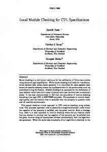
The trivial algorithm to enumerate all subgraphs of a graph would start with a single vertex, then repeatedly add on neighboring vertices until all vertices belong to the subgraph. This process would be repeated for each vertex in the subgraph. Although conceptually simple, this algorithm is computationally intractable because each unique subgraph is potentially duplicated an exponential number of times. Our algorithm (Figure 4.1) enumerates each subgraph exactly once [14]. We require that an index be assigned to each vertex
1. Assign unique integer indices to each vertex in circuit graph C. 2. foreach v ∈ V (C): 3. Create a subgraph H containing v. 4. Determine F (H) and F R (H). 5. foreach vertex u ∈ F R (H): 6. Create a subgraph H 0 = H + u. 7. If H 0 is not a subcircuit, add necessary vertices if possible or discard. 8. If H 0 is not contained, add necessary vertices if possible or discard. 9. Output H 0 . 10. Return H 0 to Step 4. 11. End foreach. 12. End foreach.
Figure 4.1: Algorithm for subcircuit enumeration. and subgraph. For a vertex v, v.index is an integer unique to that vertex. For a subgraph H, H.index is equal to the highest index of its constituent vertices. This index provides a method for creating an ordering between any two vertices in relation to the subgraph being created. This ordering results in exactly one path of vertex addition to the creation of any subgraph. The first step is to assign the indices to the vertices. The only guidelines are: it must be an integer, it must be unique, and the index of a vertex should be higher than those of the vertices that feed into it. This can be done with an O(n) breadth-first traversal of the circuit graph. Note that cycles within the graph do not cause a complication because the last guideline above need not be satisfied. Only the first two guidelines must be satisfied; the third simply reduces the computational effort. Next, a vertex may be arbitrarily chosen as the starting point of the enumeration. Each vertex will serve as a starting point eventually. A subgraph, H, is created containing only that vertex. Of the neighboring vertices, N (H), those that have an index that is less than that of H are considered to be within the frontier of that subgraph, denoted F (H). Definition 4.5 The frontier F of a subgraph H is all v such that v ∈ N (H) and v.index < H.index. The reachable frontier of the subgraph, F R (H), contains all of the vertices that may be added to H without creating a subgraph that may be duplicated. When a vertex v is added to a subgraph H, it invalidates other vertices in FR (H) for addition, specifically those that have an index that is greater than that of v. Definition 4.6 The reachable frontier of a subgraph H is denoted by F R (H) and consists of all of the vertices v that may be added to H. For a subgraph Hi = Hi−1 + vi , F R (Hi ) consists of all u such that: u ∈ F(Hi ) and either 1. u 6∈ F(Hi−1 ) or 2. u ∈ F(Hi−1 ) and v ∈ F R (Hi−1 ) and u.index < vi .index. Note that the only members of F (Hi ) that may be excluded from F R (Hi ) are those that were members of the reachable frontier of
Hi−1 , the subgraph that became Hi by the addition of the vertex vi . Any vertices that become reachable by the addition of vi are members of F R (Hi ), regardless of their indices. This ensures that all neighboring vertices are considered for addition at least once. By enforcing the rule that the only vertices that may be added to a subgraph H are members of F R (H), it is possible to enumerate each subgraph once and only once [14].
4.2
Restrictive Enumeration
The number of subgraphs within a graph can cause their enumeration to be computationally intractable for reasonably sized circuits. However, it is not necessary to enumerate all subgraphs; only the subcircuits (Definition 4.2) are of interest. A trivial solution would enumerate all subgraphs, then discard any that are not subcircuits. This does not provide the performance we require. Instead, when our algorithm encounters a subgraph that is not fully specified, it attempts, by adding necessary vertices, to create a subcircuit from it. That process continues iteratively until H is a subcircuit or until some vertex that must be added to H is not a member of F R (H). The subgraph is then discarded. Although this process produces some overhead, the benefit of enumerating the subcircuits alone far outweighs this cost. There are 98,922 unique subgraphs in a 3-bit Adder, but only 522 subcircuits. Our ongoing research considers improvements to this approach. The enumeration of contained subcircuits proceeds in a similar manner, though in addition to adding vertices to create a subcircuit, it is also necessary to add vertices to create contained subcircuits. The processing advantage to enumerating only this subset of the subcircuits, contained subcircuits, is significant.
4.3
Heuristics
Although placing a limitation on the types of subgraphs that are created is an improvement, the computation effort for large circuits can be excessive. There are several techniques that can be applied to reduce complexity without compromising its effectiveness. Preliminary Partitioning. Standard algorithms to divide the circuit into partitions [1] can be applied. These algorithms are designed to partition circuits to a specified partition size along logi-
Original Circuit
Gates
1-bit Adder 2-bit Adder 3-bit Adder C17 majority b1 cm138a cm152a cmb*
8 15 22 24 24 25 33 35 86
Unique Subgraphs number time 114 0.01 3,408 0.14 98,922 4.79 40,729 1.79 147,366 7.41 1,066,434 56.60 N/A N/A N/A -
Candidate Subcircuits number time 18