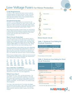
protection may be provided by fuses, overload relays or motor thermal protectors.
... The motor branch circuit fuses may be sized as large as shown in Table 2 ...
Shunt capacitor banks are used to improve the quality of the electrical supply and
... This paper reviews principles of shunt capacitor bank design for substation ...
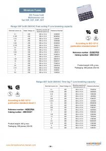
Miniature Fuses. IEC Fuses 5x20. 250VAC from 0.1 to 20A. Dimensions.
Complying with IEC-127-2 Standard Sheet 1. Product weight: 1.2g max.
Packaging: in ...
GE Multilin, USA [email protected]. ABSTRACT. Shunt capacitor banks are used to improve the quality of the electrical supply and the efficient.
of transmission capacitor banks for mitigating issues related to transient recovery voltage impacts on the circuit breaker protecting the capacitor bank. The design ...
According to IEC-127-2 publication standard sheet 2. Range 5ST 5x20 250VAC
Time lag T Low breaking capacity. Reference number : Catalog number :.
Apr 25, 2018 - PRESS RELEASE. PAGE 1 OF 3. WWW.MERSEN.COM. MERSEN: LIKE-FOR-LIKE GROWTH OF 11% IN THE FIRST QUARTER OF 2
Mersen integrates its extensive cooling expertise and patented heatsink
technology into ... By cooling power electronics in wind or solar power systems…
This chapter builds a deep understanding of the modern MOS ... often a better
structure for studying the MOS capacitor properties than the MOS capacitor itself
...
Abstract: A rule-based scheme is investigated for capacitor voltage balancing in a multilevel ... The multilevel flying capacitor inverter (MFCI), a relatively.
enable voltage clamping in multiple level power converters. Fig. 1 shows an
example of a three-phase four-cell circuit supplying an inductive load. Each
phase ...
However, as this tip sheet will explain, using class H fuses may ... renewable type
shall only be permitted to be used for replacement in existing installations ...
Jan 16, 2017 - Ends are closed with PVC slip caps and dielectric grease. Both ends have a 6â nylon plug (with greased 'O' rings?) in the innermost pipe.
Aug 5, 2013 - ABSTRACT. All modes of operation of a two-capacitor generator based on overflow of the charge accumulated in capacitors through the load ...
There was a problem previewing this document. Retrying... Download. Connect more apps... Try one of the apps below to op
www.candura.com. This high speed voltage transient was captured by a
PowerPro. This transient is typical of a capacitor bank being connected to a ...
Capacitor Switching Techniques. S.J. Kulas. Faculty of Electrical Engineering.
Warsaw University of Technology. GG 130, Pl. Politechniki 1, 00-662 Warsaw, ...
Supercapacitors. Supercapacitors also called ultracapacitors and electric double
layer capacitors (EDLC) are capacitors with capacitance values greater than ...
Capacitor Bank Panels are easy to install and can be deployed virtually
anywhere in the network. Its installation has other beneficial effects on the system
such ...
In this work the propulsion force developed in an asymmetric capacitor will be ... mechanism that acts on the asymmetrical capacitors, and also to understand ...
Dec 8, 2014 - Patent 20070278551 (2007) is analysed in three dimensions. ... The geometry considered here was taken from a US Letters Patent [1].
charged with an energy loss resulting through the application of ... In previous works the energy loss has ... In this work it is shown that .... The kinetic energy of the charge carriers derived through Poynting's theorem or through the relation: is
The primary responsibility of a capacitor fuse is to isolate a shorted capacitor
before the ... in each ungrounded conductor of each capacitor bank. (see Figure
1).
Capacitor Protection The primary responsibility of a capacitor fuse is to isolate a shorted capacitor before the capacitor can damage surrounding equipment or personnel. Typical capacitor failure occurs when the dielectric in the capacitor is no longer able to withstand the applied voltage. A low impedance current path results. The excessive heat generated builds pressure and can cause violent case rupture. A fuse will isolate the shorted capacitor before case rupture occurs.
Fuse Placement
The Code requires that an overcurrent device be placed in each ungrounded conductor of each capacitor bank (see Figure 1). The Code further requires that the rating or setting of the over-current device be as low as practicable. A separate overcurrent device is not required if the capacitor is connected on the load side of a motor-running overcurrent device. Fusing per the Code provides reasonable protection if the capacitors are the metallized film self-healing type. If not, each capacitor should be individually fused as shown in Figure 2. Fusing each individual capacitor is especially important in large banks of parallel capacitors. Should one capacitor fail, the parallel capacitors will discharge into the faulted capacitor and violent case rupture of the faulted capacitor can result. Individual capacitor fusing eliminates this problem. If the capacitors are to be placed in banks comprised of both series and parallel combinations, the capacitor manufacturer must be consulted for fuse placement recommendations. The opening of improperly placed fuses can cause overvoltage and result in damage to other capacitors in the network.
Ampere Rating
How much overcurrent can a capacitor withstand? What effects do neighboring capacitors have on the inrush of a given capacitor? These and other questions influence fuse selection. Circuit analysis can be very complex. It is best to consult the capacitor manufacturer for specific recommendations. For applications 600V or less in lieu of specific fusing recommendations from the capacitor manufacturer, we suggest a Mersen A60C Type 121 or an A6Y Type 2SG fuse sized at 165% to 200% of the capacitor’s current rating (contact factory for technical data). If these fuses are not dimensionally acceptable, then a non-time delay Class J or Class RK1 fuse could be used and sized at 185% to 220% of the capacitor’s current rating.
P40
For applications over 600V to 5.5kV, we suggest Amp-Trap A100C to A550C capacitor fuses. These medium voltage fuses are available in a variety of voltage ratings and mounting configurations. Refer to pages E36 for specific data. Medium voltage capacitor fuses are sized at 165% to 200% of the capacitor current rating. Capacitor fuses are selected for their ability to provide short circuit protection and to ride through capacitor inrush current. Inrush current is affected by the closing angle, capacitance, resistance and inductance of the circuit, and varies from one application to another. Inrush lasts for less than 1/4 cycle and is typically less than 25 timess the capacitor’s current rating. Steady state capacitor current is proportional to the applied voltage and frequency. Since voltage and frequency are fixed in power factor correction applications, the capacitor is not expected to be subjected to an overload. Therefore, capacitor fuses are not selected to provide overload protectors for the capacitor.
Capacitor Protection kVAR vs. AMPS The capacitor’s current rating can be derived from its kVAR rating by using the following formula: kVAR x 1000 = amps volts
1 kVAR = 1000VA (Reactive)
Example#1: What fuse would you recommend for a three phase capacitor rated 100kVAR at 480 volts? 100,000 volt-amps = 208 amps 480 volts
Example#2: What fuse would you recommend for a three phase capacitor rated 2.4kV, 100kVAR?
Calculate Capacitor Current = 100,000 volt-amps = 24A
√ 3 x 2400V fuse size 24 x 1.65 = 39A
24 x 2.00 = 48A
We suggest a 40 or 50 amp fuse rated at least 2400V A250C50-XX, where XX is the type of mounting needed.
To determine line current, we must divide the 208 amps, which is the three phase current by √ 3 208 = 120 amps √3 If an A6OC Type 121 fuse is to be used, size the fuse at 165% to 200% of line current. 120 amps x 1.65 = 198 amps 120 amps x 2.00 = 240 amps Suggestions: A60C200-121 or A60C200-121TI
If a Class J or a Class RK1 is to be used, size the fuse at 185% to 220% of line current. 120 amps x 1.85 = 222 amps 120 amps x 2.20 = 264 amps