Proceedings of the World Congress on Engineering 2014 Vol I, WCE 2014, July 2 - 4, 2014, London, U.K.
Capacity Integration into a Microgrid, a Tool for Electrical Energy Supply Cost Reduction in NigeriaCovenant University as a Case Study H .E Orovwode, A.O. Adegbenro, C. O. A. Awosope, F.E.Idachaba, A Abdulkareem I. Introduction The use of fossil fuel for the generation of electricity has brought three main challenges for the world to deal with: availability, cost of procuring the fuel and greenhouse gas emission (GHS) which is the greatest threat to the environment in that it depletes the ozone layer. Consequent upon this, power generation techniques that could meet the load demand as well as encourage greenness and efficiently supply electricity are being encouraged worldwide. Local generation of power at distribution voltage level using non-conventional and renewable energy sources is becoming evident. Most of this individual generation does not enjoy the economies of scale being provided by central generating schemes. The promise, by researchers all over the world, of new and renewable energy sources and its great expectations to take over from fossil fuels has not yet been realized. New energy fuels, like biofuels have proved to be uneconomical [1], and new energy carriers – hydrogen energy, fuel cells, etc. are still in the research laboratories rather than in markets and are unlikely to have a serious impact on the energy scene for years to come.[2] Since oil is not a renewable energy source, its reserve will definitely be exhausted in time to come. Certainly, the rate of new petroleum discoveries is declining relentlessly, while rates of oil consumption have risen steadily. The underlying truth is that fossil fuels are ultimately finite resources, and considering the current global consumption rates, they will be depleted as rapidly as they have risen to dominance, therefore, the need to efficiently utilize available resources. One method of achieving this is by pulling together these power generating resources which run on fossil fuel to form a microgrid. This method is
Abstract - The cost implication of running a cluster of stand-alone power generating plants was investigated using the generating capacities of the generators and consumption (load) profile obtained from a campus based substation. Analysis of the results revealed a lot of unused available capacity within the system which invariably increases the operating cost of power generation within the campus. Integrating the power generators into a microgrid was suggested where there will be a common pool of energy sources and all loads attached to the network. The proposed network model seeks to reduce power plant engagement by integrating the generating power plants into a microgrid system. To overcome the challenge of synchronization in the AC platform as the power generators are dissimilar, the network is designed to operate as a DC microgrid where the AC generating plants and loads will be interfaced by converters (rectifiers) and inverters respectively. This method reduced the unused capacity being wasted by reducing power plant engagement and consequently reducing the running cost of power generation in the campus. Keywords: integration
energy,
autonomous,
microgrid,
H .E Orovwode, C. O. A. Awosope, F.E.Idachaba, A Abdulkareem are with Electrical and Information Engineering Department, School of Engineering , College of Science and Technology, Covenant University, Ota, Nigeria. A.O. Adegbenro is with National Centre for Energy Efficiency and Conservation, Faculty of Engineering, University of Lagos.
[email protected] [email protected] [email protected] [email protected] [email protected]
ISBN: 978-988-19252-7-5 ISSN: 2078-0958 (Print); ISSN: 2078-0966 (Online)
WCE 2014
Proceedings of the World Congress on Engineering 2014 Vol I, WCE 2014, July 2 - 4, 2014, London, U.K.
capable of reducing the power plant operating time, increase the plant’s lifespan, save fuel and reduce GHG emission.
before any distributed resource can be admitted into the microgrid [12], [13]. Analysis carried out on a microgrid depends on the intention of the analyst. It could be to determine the best energy mix to be employed in the given area [14], the feasibility of using the available sources to meet the load demand [15 ], the economy of running an autonomous microgrid in comparism to main grid extension[16 ] or when to sell or buyback power if the microgrid is to be interconnected with the main utility grid.
II. The microgrid concept Though there is no generally agreed definition for a microgrid, however, a microgrid can be described as a small-scale power supply network that is designed to provide power for a small community which may range from a typical housing estate, isolated rural communities, to mixed suburban environments, academic or public communities such as universities or schools, to commercial areas, industrial sites and trading estates, or municipal regions. The main concept that differentiates this method of power supply from a conventional power utility is that the power generators are small (often referred to as microgenerators, of a similar size as the loads within the microgrid), they are distributed and located in close proximity to the loads. [3,4,5,6,7]
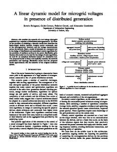
III. The development of the integrated electric power network The Covenant University Electric Power Network (CUEPN) in the off-grid mode has a total installed power generating capacity of 9750kVA from eighteen (18) diesel generators rated between 250kVA and 1000kVA installed at eight different locations on the campus (CBS, CST, CU WATER WORKS, PG/CHAPEL, CLR, HOSTEL, ENG BLOCK, NEW ESTATE ) . Each power house is tied to a specific load point as shown in Figure 1. When power supply from the public utility fails, eight generators will have to run simultaneously to produce power between 3750kVA (minimum units combination) and 6000kVA (maximum units combination) at any instant in time. The eighteen (18) diesel generators were sourced from three different manufacturers: Caterpillar (13), Perkins (2) and Cummins (3). A study carried out shows that while some of the generating sets are overloaded, others are operating below optimum capacity [17].
Three categories of microgrid exist depending on the source and load. They are AC-AC, DC-AC and AC-DC-AC (hybrid). The choice of the configuration and architecture depends on the nature of the energy sources and the load available. The two most important factors used in determining the classification are (1) whether the microgrid will be operated as an island or to be connected to a main or larger grid and (2) the type of microsources (constant or variable output). The type and extent of the distribution within the microgrid is another important distinction, but distribution has multiple alternatives, which may make it hard to agree on defining thresholds. Size could also be another important criterion [8, 9, 10 ] For power generators to operate as a microgrid, they must operate in parallel. Parallel operation of the distributed generators to operate as a microgrid, (as the points of interconnection (PI) switches are closed to meet demand requirement), presupposes that the generators must be synchronizable otherwise the distributed generators cannot supply a common alternating current (AC) load [11]. The implication of this is that the characteristics of the generators must be pre-selected to meet the requirements set down by the network developer
In the proposed network, the power generating plants will remain in their present locations. The outputs will be tied together to form a ringconnected microgrid. Since the power generators in the University cannot be synchronized on the AC platform because of technical limitations of the dissimilar generators (frequency, phase and terminal voltage matching), the outputs of the generators will be fed to rectifier units where the AC will be converted to DC. The network will be a DC microgrid. Each load center will be interfaced with an inverter that will convert the grid DC
ISBN: 978-988-19252-7-5 ISSN: 2078-0958 (Print); ISSN: 2078-0966 (Online)
WCE 2014
Proceedings of the World Congress on Engineering 2014 Vol I, WCE 2014, July 2 - 4, 2014, London, U.K.
voltage to AC voltage as required by the load. There will be a point of common coupling with controllers attached to each generation and loading point and coordinated from the central control unit. The control algorithm is such that all management a strategy with respect to university’s peculiar load profiles was taken care of. The system will is fully optimized to ensure effective capacity utilization. Figure 2 shows the architecture of the proposed network.
IV. The simulation of the integrated power network The National Renewable Energy Laboratory (NREL)’s Hybrid System Optimization Model for Electric Renewables (HOMER 2.81) was used as the simulation, sizing and optimization tool. This software contains a number of energy components and it evaluates suitable options based on cost and availability of energy resources [18]. The software requires pieces of information related to energy resources, which in the case of Covenant University, are diesel-powered internal combustion engines, economical constraints, energy storage medium and system control strategies. It also requires inputs such as component plant type, its size, number of units, capital, replacement, and operation and maintenance costs, efficiency and operational life to adequately generate the result. The three models that were simulated, the generators feeding their individual loads, the generators integrated on the Alternating current platform (ACS) (Figure 3a) in which synchroscopes were used assuming the machine parameters match and the generators integrated on the Direct current (DCS) platform where rectifiers and inverters were introduced since the machine parameters did not match . (Figure 3b).
The cost function of the power plant is given as : C(i) =αi +βiPi + ϒiPi2
(N/hr)
(1)
where αi, βi & ϒi are constants of the i-th power plant Pi - power output of the i-th generator For the existing network with m generating units, the annual total cost will be Ct= C1+ C2+ C3+……..…+Cm =
m
8760
i 1
t 1
c
(N/yr)…
i ( Pi )
(2)
In the integrated power network, the generators are connected to a microgrid through their respective converters. The generators are economically dispatched according to the load demand. In this method, all generators were not engaged all the time. The total annual cost of fuel was less and is given as
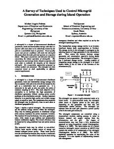
V. Results and Discussion The results generated by the software predict an annual fuel consumption pattern, the total fuel to be used during the period and the amount of fuel that could be saved under review for the three system configurations. These are presented in Tables 1 and 2. It can be seen from Table 1 that the best configuration in terms of less fuel consumption is the ACS model but technical limitation (frequency, phase and generators’ electrical parameters mixmatch) makes this configuration impracticable (except using power conditioners which this model seeks to solve). Figure 4 shows the graphical presentation of the total annual fuel consumption by the generating plants for the three system configurations while Figures 5 and 6 show the annual fuel saved and the percentage of the fuel that could be saved if either the ACS or DCS configuration is adopted.
C′t= C1+ C2+ C3+………+Cn n
8760
i 1
t 1
=
c
i ( Pi )
(N/yr)…
(3)
Where ‘n’ is the number of selected combination of generators that will satisfy the load subject to system and operational constraints. The cost computation can be done using an appropriate algorithms and methods or optimization software.
ISBN: 978-988-19252-7-5 ISSN: 2078-0958 (Print); ISSN: 2078-0966 (Online)
WCE 2014
Proceedings of the World Congress on Engineering 2014 Vol I, WCE 2014, July 2 - 4, 2014, London, U.K.
[7].
VI. Conclusion The fuel cost implication of running a cluster of autonomous power generating plant was investigated and presented using the generating capacity and consumption (load) profile obtained from a campus base substation. Analysis of the results revealed a lot of unused but available capacity within the system which invariably increases the operating cost of power generation within the campus. Integrating the power generators into a microgrid was suggested where there will be a common pool of energy sources and all loads attached to the network. The proposed network model was aimed at reducing power plant engagement by integrating the power plants into a microgrid system. The power plants are not compactable if they were to be synchronized. To overcome the challenge of synchronization in the AC platform, the network is designed to operate as a DC microgrid where the AC generating plants and loads will be interfaced by converters (rectifiers) and inverters. This approach reduced the unused capacity by reducing power plant engagement and consequently reducing the running cost of power generation on the campus.
[8].
[9].
[10].
[11]. [12].
[13].
[14]. [15]. [16].
References [1]. [2].
[3].
[4]. [5]. [6].
[17].
David Pimentel and Tad W. Patzek (2008) “Biofuels, Solar and Wind as Renewable Energy Systems” pp 373-394, Springer Netherlands. Global Trends in Sustainable Energy Investment report (2007) “Analysis of Trends and Issues in the Financing of Renewable Energy and Energy Efficiency in OECD and Developing Countries” United Nations Environment Programme and New Energy Finance Ltd. Available at http://sefi.unep.org/fileadmin/media/sefi/docs/publications/SEFI _Investment_Report_2007.pdf Hisham Khatib (2003) “Economic Evaluation of projects in the Electricity supply industry” revised edition IET press , London United Kingdom. Lasseter, R, Akhil, A, Marnay, C, Stephens, J, Dagle, J, Guttromson, R, Meliopoulous, AS, Yinger, R, Eto, J. The CERTS microgrid concept, White paper on Integration of Distributed Energy Resources. CERTS, Canada, Consultant Report no. P500-03-089F, October 2003. Pepermansa G, Driesenb J, Haeseldonckxc D, Belmansc R, D’haeseleer W. Distributed generation: definitions, benefits and issues. Energy Policy 2005; 33(18):787–98. Venkataramanan G, Marnay C. A large role for microgrids: are microgrids a viable paradigm for electricity supply expansion? IEEE Power Energy Magazine 2008;May/June:78–82. Z. Ye, R. Walling, N. Miller, P. Du, K. Nelson “The Definition of Microgrids “General Electric Global Research Cente Niskayuna, New York.
[18].
A.G. Tsikalakis, N.D. Hatziargyriou, “Centralized Control for Optimizing Microgrids Operation”, Energy Conversion, IEEE Transaction on Power Electronics, Vol. 23, No. 1. (2008). E.J. Honton, “DR Interconnection Issues: Standards, Technologies and Impacts on the Business Deal”, Presented at EAC Workshop on DR for TVA Distributors, Knoxville, TN. September 10, 2002. Ito, Y. ; Zhongqing, Y. ; Akagi, H. “DC microgrid based distribution power generation system” Power Electronics and Motion Control Conference, 2004. IPEMC 2004. The 4th International Volume: 3 , 2004 , Page(s): 1740 – 1745 Fei Ding ; Loparo, K.A. ; Chengshan Wang “Modeling and simulation of grid-connected hybrid AC/DC microgrid” Power and Energy Society General Meeting, 2012 IEEE 2012 , Page(s): 1 – 8. Z. Contreras, “Economic valuation framework of distributed electricity supply”, Centre for Energy and Environmental Markets publication, June 22 - 27, 2008, London, UK. C. Marnay, F. J. Rubio, and A. S. Siddiqui, “Shape of the Microgrid”, Presentation given in the panel Role of Distributed Generation in Reinforcing the Critical Electric Power Infrastructure- at the IEEE Winter Meeting, Columbus, OH, 31 January, 2001. F. Nguyen, “Centralized Versus Distributed Generation Options”, Moen/Iea Joint Workshop on Fuel Options for Power Generation in Asian, Bangkok, Thailand, 22- 23 September, 2008. Akella AK, Sharma MP, Saini RP. Optimum utilization of renewable energy sources in a remote area, Renewable and Sustainable Energy Reviews 2007;11:894-908. Bekele G, Tadesse G. Feasibility study of small Hydro/PV/Wind hybrid system for offgrid rural electrification in ethiopia. Applied Energy 2012; 97(0):5-15. Dakkak, M., Hirata, A., Muhida, R., Kawasaki, Z.,.’ Operation strategy of residential centralised photovoltaic system in remote areas’. 2003Renewable Energy 28, 997–1012 J. C. Ekeh and O. S. James, “Optimal Use of the Existing Generating Plants in a Micro Grid: A Case Study of Covenant University, Canaanland Ota, Ogun State”. Technical report submitted to the management of Covenant University, Ota, towards 2014 Strategic planning, , 2007. (Unpublished). HOMER 2.14, National Renewable Energy Laboratory (NREL), 617 Cole Boulevard, Golden, CO 80401- 3393, URL: http://www.nrel.gov/homer.
Figure.1.The existing power network distribution layout and the facilities’ location
ISBN: 978-988-19252-7-5 ISSN: 2078-0958 (Print); ISSN: 2078-0966 (Online)
WCE 2014
Proceedings of the World Congress on Engineering 2014 Vol I, WCE 2014, July 2 - 4, 2014, London, U.K.
ISBN: 978-988-19252-7-5 ISSN: 2078-0958 (Print); ISSN: 2078-0966 (Online)
WCE 2014
Proceedings of the World Congress on Engineering 2014 Vol I, WCE 2014, July 2 - 4, 2014, London, U.K.
(a) (b) Figure 3: the generators’ integration (a) Alternating current (ACS) and (b) the Direct current (DCS)
Table 1: Power Generating centers’ annual Fuel Consumption CBS
CST
DCS (L/yr)
348315
ACS (L/yr) Existing (L/yr)
model
PG/ CHAPEL
CLR
HOSTEL
ENG BLK
NEW ESTATE
Total
1346565
CU WATER WORKS 1331715
1247380
1050303
665610
209880
786720
6986488
364806
1432475
1347802
1136329
620270
265815
1094983
174448
6436928
1568040
1568040
1568040
1568040
1568040
1568040
1568040
1568040
12544320
Table 2: Analysis of the Annual Fuel consumption
DCS (L/yr)
total annual fuel consumed (L) 6,986,488
annual fuel saved (L) 5,557,832
% annual fuel saved 44.3
ACS (L/yr)
6,436,928
6,107,392
48.7
Existing model (L/yr)
12544320
0
0
ISBN: 978-988-19252-7-5 ISSN: 2078-0958 (Print); ISSN: 2078-0966 (Online)
WCE 2014
Proceedings of the World Congress on Engineering 2014 Vol I, WCE 2014, July 2 - 4, 2014, London, U.K.
1800000 1600000 1400000 1200000 1000000 800000 600000 400000 200000 0
DCS (Liters/yr) ACS (Liters/yr) Existing model (Liters/yr)
CHAPEL CBS
CST
CU WATER WORKS
PG/
CLR
HOSTEL
ENG BLK
NEW ESTATE
Figure 4: Annual Fuel Consumption of the Power Generating centers
% annual fuel saved (Liters)
Total annual fuel consumed (Liters)
44.3
12544320
6,986,488
48.7
6,436,928
0 DCS (Liters/yr)
ACS (Liters/yr)
Existing model (Liters/yr)
DCS (Liters/yr)
Figure 5: Total Annual Fuel Consumption for the three system configurations.
ACS (Liters/yr)
Existing model (Liters/yr)
Figure 6: Percentage of Fuel that could be saved operating DCS or ACS configuration.
ISBN: 978-988-19252-7-5 ISSN: 2078-0958 (Print); ISSN: 2078-0966 (Online)
WCE 2014