NDT Non-Destructive Test
and
Pipe line Inspection Methods Presented By
Dr. Essam Bahgat Moustafa
Dr. Essam Bahgat Moustafa
1
Course Contents 01
NDT Introduction
02
Common NDT Methods
03
Process and Application of each NDT Method Pipe line Inspection Methods
04
NDT
Dr. Essam Bahgat Moustafa
01
2
01
NDT Introduction
Definition of NDT The use of noninvasive techniques to determine the integrity of a material, component or structure or quantitatively measure some characteristic of an object. i.e. Inspect or measure without doing harm. Dr. Essam Bahgat Moustafa
3
Why Nondestructive? Test piece too precious to be destroyed Test piece to be reuse after inspection Test piece is in service For quality control purpose Something you simply cannot do harm to, e.g. fetus in mother’s uterus
Dr. Essam Bahgat Moustafa
4
02
Common NDT Methods Visual Liquid or Dye Penetrant Magnetic Particle Eddy Current
Ultrasonic X-ray
Thermography
Dr. Essam Bahgat Moustafa
5
Major types of NDT • Detection of surface flaws Visual Magnetic Particle Inspection Fluorescent Dye Penetrant Inspection • Detection of internal flaws Radiography Ultrasonic Testing Eddy current Testing Dr. Essam Bahgat Moustafa
6
Visual Inspection Visual testing is the most basic and common inspection method involves in using of human eyes to look for defects. But now it is done by the use special tools such as : Mirrors (especially small, angled mirrors), Magnifying glasses, Microscopes (optical and electron), Borescopes and fiber optic borescopes. Feeler Gauges
Dr. Essam Bahgat Moustafa
7
Liquid Penetrant This method is commonly used for detect the surface cracks or defects. Dye penetrant Testing (DPT) is one of the most widely used nondestructive Testing (NDT) methods. DPT can be used to inspect almost any material provided that its surface is not extremely rough.
Dr. Essam Bahgat Moustafa
8
Penetrant Types Dye penetrants
Fluorescent penetrants
– The liquids are colored so that they provide good contrast against the developer – Usually red liquid against white developer – Observation performed in ordinary daylight or good indoor illumination
– Liquid contain additives to give fluorescence under Ultraviolet (UV) –
Object should be shielded from visible light during inspection
– Fluorescent indications are easy to see in the dark
Standard: Aerospace Material Specification (AMS) 2644.
Dr. Essam Bahgat Moustafa
9
Dye Penetrant Testing Process Three liquids are used in this method. 1. Cleaner 2. Penetrant 3. Developer
Dr. Essam Bahgat Moustafa
10
Dye Penetrant Testing of a Boiler
Dr. Essam Bahgat Moustafa
11
After Dye Penetrant Testing , there are two surface cracks are Detected.
Dr. Essam Bahgat Moustafa
Cracks on surface
12
Advantages The method has high sensitive to small surface discontinuities. The method has few material limitations, i.e. metallic and nonmetallic, magnetic and nonmagnetic, and conductive and nonconductive materials may be inspected. Large areas and large volumes of parts/materials can be inspected rapidly and at low cost.
Parts with complex geometric shapes are routinely inspected. Indications are produced directly on the surface of the part and constitute a visual representation of the flaw. Penetrant materials and associated equipment are relatively inexpensive. Dr. Essam Bahgat Moustafa
13
Disadvantages Only surface breaking defects can be detected.
Only materials with a relative nonporous surface can be inspected. Preclearing is critical as contaminants can mask defects. Metal smearing from machining, grinding, and grit or vapor blasting must be removed prior to Liquid Penetrant Inspection[LPI]. The inspector must have direct access to the surface being inspected. Surface finish and roughness can affect inspection sensitivity. Multiple process operations must be performed and controlled. Post cleaning of acceptable parts or materials is required.
Chemical handling and proper disposal is required.
Dr. Essam Bahgat Moustafa
14
Application Aerospace :Typical Components that are checked by this method include Turbine, rotor disc, blades, aircraft wheels, Casting, forged parts and welded assemblies
Automobiles: Many automotive parts particularly aluminum castings and forging including pistons and cylinder heads are subjected to this form of quality checks before assembly
Railways: LPI to detect fatigue cracking is also used for the regular in service examination of the bogie frames of railway locomotive and the rolling stock
Tool and dies: field drilling rays, drill pipes, castings and drilling equipment's inspected by this methods
Inspection on reactors and tank: Tanks, vessels, reactors, piping, dyers in the chemical, petro-chemical industries.
Dr. Essam Bahgat Moustafa
15
Dr. Essam Bahgat Moustafa
16
Magnetic Particle Testing This method is suitable for the detection of surface and near surface discontinuities in magnetic material, mainly ferrite steel and iron. Magnetic particle Testing (MPT) is a nondestructive testing method used for defect detection. MPT is fast and relatively easy to apply, and material surface preparation is not as critical as it is for some other NDT methods. Dr. Essam Bahgat Moustafa
17
Basic Principle of MPT In the first figure the magnetized metal has no crack and there only two poles that is north pole and south pole. And in second figure the magnetized metal has a crack and at the crack point there creates another north and south pole for the magnetic flux leakage.
Dr. Essam Bahgat Moustafa
18
The part is magnetized. Finely milled iron particles coated with a dye pigment are then applied to the specimen. These particles are attracted to magnetic flux leakage fields and will cluster to form an indication directly over the discontinuity. This indication can be visually detected under proper lighting conditions.
Dr. Essam Bahgat Moustafa
19
Magnetizing the object There are a variety of methods that can be used to establish a magnetic field in a component for evaluation using magnetic particle inspection. It is common to classify the magnetizing methods as either direct or indirect.
Direct magnetization: current is passed directly through the component.
Clamping the component between two electrical contacts in a special piece of equipment Dr. Essam Bahgat Moustafa
Using clams or prods, which are attached or placed in contact with the component 20
Indirect magnetization: using a strong external magnetic field to establish a magnetic field within the component
(a) Permanent magnets
(c) Electromagnets
(b) Coil shot Dr. Essam Bahgat Moustafa
21
Magnetic Particle Testing in Super heater Pipe Welding
Iron particles make a cluster at the welding joint for magnetic flux leakage because of welding defects. Welding cracks Dr. Essam Bahgat Moustafa
22
Magnetic particles Pulverized iron oxide (Fe3O4) or carbonyl iron powder can be used Colored or even fluorescent magnetic powder can be used to increase visibility Powder can either be used dry or suspended in liquid
Dr. Essam Bahgat Moustafa
23
Advantages of MPI One of the most dependable and sensitive methods for surface defects Fast, simple and inexpensive Direct, visible indication on surface Unaffected by possible deposits, e.g. oil, grease or other metals chips, in the cracks Can be used on painted objects Surface preparation not required Results readily documented with photo or tape impression Dr. Essam Bahgat Moustafa
24
Limitations of Magnetic Particle Testing Material must be ferromagnetic.
Orientation and strength of magnetic field is critical. Detects surface and near-to-surface discontinuities only.
Large currents sometimes require.
Dr. Essam Bahgat Moustafa
25
Dr. Essam Bahgat Moustafa
26
Radiography
X-rays
were discovered in 1895 by Wilhelm Conrad Roentgen (1845-1923) who was a Professor at Wuerzburg University in Germany. Working with a cathode-ray tube in his laboratory, Roentgen observed a fluorescent glow of crystals on a table near his tube. 1895
Dr. Essam Bahgat Moustafa
27
Radiography Testing The radiation used in radiography testing is a higher energy (shorter wavelength) version of the electromagnetic waves that we see as visible light. The radiation can come from an X-ray generator or a radioactive source. Radiographic Testing Method is nothing but to take the shadow picture of an object onto a film by the passage of X-ray or Gamma ray through it. It is the same as the medical radiography (X-ray). Only difference in their wave length. Dr. Essam Bahgat Moustafa
28
Dr. Essam Bahgat Moustafa
29
Production of X-rays X-rays are produced whenever highspeed electrons collide with a metal target.
A source of electrons – hot W filament, a high accelerating voltage (30-50kV) between the cathode (W) and the anode and a metal target. The anode is a water-cooled block of Cu containing desired target metal.
W
target
Dr. Essam Bahgat Moustafa
X-rays
Vacuum
30
Absorption of x-ray • All x-rays are absorbed to some extent in passing through matter due to electron ejection or scattering. • The absorption follows the equation
I I 0e where
x
I 0e
x
I0
I is the transmitted intensity; x is the thickness of the matter;
,
I
x
is the linear absorption coefficient (element dependent); is the density of the matter; (/) is the mass absorption coefficient (cm2/gm). Dr. Essam Bahgat Moustafa
31
Essential Elements for Radiography Testing A source of penetrating radiation, such as an X-ray machine.
The object to be radiographed, such as a weldment. A recording or viewing device, usually photographic (Xray) film enclosed in a light tight holder. A qualified radiographer trained to produce a satisfactory exposure.
A person skilled in the interpretation of radiographs
Dr. Essam Bahgat Moustafa
32
Radio Isotope (Gamma) Sources As the material rids itself of the neutron, energy is released in the form of gamma rays. Two of the more common industrial Gamma-ray sources are Iridium-192 and Colbalt-60. These isotopes emit radiation in two or three discreet wavelengths. Cobalt 60 will emit a 1.33 and a 1.17 MeV gamma ray, and iridium-192 will emit 0.31, 0.47, and 0.60 MeV gamma rays.
Advantages of gamma ray sources include portability and the ability to penetrate thick materials in a relativity short time. Disadvantages include shielding requirements and safety considerations. Dr. Essam Bahgat Moustafa
33
Limitations of Radiography There is an upper limit of thickness through which the radiation can penetrate, e.g. -ray from Co-60 can penetrate up to 150mm of steel The operator must have access to both sides of an object Highly skilled operator is required because of the potential health hazard of the energetic radiations Relative expensive equipment
Dr. Essam Bahgat Moustafa
34
Advantages of Radiography Information is presented pictorially. A permanent record is provided which may be viewed at a time and place distant from the test. Useful for thin sections.
Sensitivity declared on each film suitable for any material
Dr. Essam Bahgat Moustafa
35
X-Rays Applications X-rays are used in industrial, medical, pure science research and X-ray
crystallography etc… X-rays are used to detect defects in radio valves. X-rays are used to detect cracks in structures. X-rays are used to analyses the structures of alloys and other composite bodies by diffraction of X-rays. They are also used to study are structure of materials like rubber, cellulose, plastic, fibers etc…
X-rays can destroy abnormal internal tissues. Dr. Essam Bahgat Moustafa
36
Dr. Essam Bahgat Moustafa
37
Ultrasonic Testing In ultrasonic testing, high-frequency sound waves are transmitted into a material to detect imperfections or to locate changes in material properties. The most commonly used ultrasonic testing technique is pulse echo, whereby sound is introduced into a test object and reflections (echoes) from internal imperfections or the part's geometrical surfaces are returned to a receiver. The time interval between the transmission and reception of pulses give clues to the internal structure of the material. Dr. Essam Bahgat Moustafa
38
Ultrasonic Inspection (Pulse-Echo) High frequency sound waves are introduced into a material and they are
reflected back from surfaces or flaws. Reflected sound energy is displayed versus time, and inspector can visualize a
cross section of the specimen showing the depth of features that reflect sound. initial pulse
crack echo
back surface echo
crack 0
2
4
6
8
Oscilloscope, or flaw detector screen
10
plate
Dr. Essam Bahgat Moustafa
39
Generation of Ultrasonic Waves Piezoelectric transducers are used for converting electrical pulses to mechanical vibrations and vice versa Commonly used piezoelectric materials are quartz, Li2SO4, and polarized ceramics such as BaTiO3 and PbZrO3. Usually the transducers generate ultrasonic waves with frequencies in the range 2.25 to 5.0 MHz
Dr. Essam Bahgat Moustafa
40
Ultrasonic Wave Propagation Common type
Wave Propagation Direction
• Longitudinal or Compression waves – Similar to audible sound waves – the only type of wave which can travel through liquid
• Shear or Transverse waves – Generated by passing the ultrasonic beam through the material at an angle – Usually a plastic wedge is used to couple the transducer to the material
Dr. Essam Bahgat Moustafa
41
Test Techniques Normal and Angle Beam In normal beam testing, the sound beam is introduced into the test article at 90 degree to the surface. In angle beam testing, the sound beam is introduced into the test article at some angles other than 90.
The choice between normal and angle beam inspection usually depends on two considerations: The orientation of the feature of interest the sound should be directed to produce the largest reflection from the feature. Obstructions on the surface of the part that must be worked around. Dr. Essam Bahgat Moustafa
42
Couplant A couplant is a material (usually liquid) that facilitates the transmission of ultrasonic energy from the transducer into the test specimen. Couplant is generally necessary because the acoustic impedance mismatch between air and solids (i.e. such as the test specimen) is large. The couplant displaces the air and makes it possible to get more sound energy into the test specimen so that a usable ultrasonic signal can be obtained. In contact ultrasonic testing a thin film of oil, glycerin or water is generally used between the transducer and the test surface Dr. Essam Bahgat Moustafa
43
Dr. Essam Bahgat Moustafa
44
Ultrasonic Components Piezoelectric Transducers
Pulser / Receiver
Dr. Essam Bahgat Moustafa
45
Data Presentation Ultrasonic data can be collected and displayed in a number of different formats. The three most common formats are know in the NDT world as A-scan, B-scan and C-scan presentations. Each presentation mode provides a different way of looking at and evaluating the region of material being inspected. Modern computerized ultrasonic scanning systems can display data in all three presentation forms simultaneously
Dr. Essam Bahgat Moustafa
46
A-Scan The A-scan presentation displays the amount of received ultrasonic energy as a function of time. The relative amount of received energy is plotted along the vertical axis and elapsed time (which may be related to the sound energy travel time within the material) is display along the horizontal axis. Relative discontinuity size can be estimated by comparing the signal amplitude obtained from an unknown reflector to that from a known reflector. Reflector depth can be determined by the position of the signal on the horizontal sweep.
Dr. Essam Bahgat Moustafa
47
B-Scan The B-scan presentations is a profile (cross-sectional) view of the a test specimen. In the B-scan, the time-of-flight (travel time) of the sound energy is displayed along the vertical and the linear position of the transducer is displayed along the horizontal axis. From the B-scan, the depth of the reflector and its approximate linear dimensions in the scan direction can be determined. The B-scan is typically produced by establishing a trigger gate on the Ascan. Whenever the signal intensity is great enough to trigger the gate, a point is produced on the B-scan. The gate is triggered by the sound reflecting from the back wall of the specimen and by smaller reflectors within the material. Dr. Essam Bahgat Moustafa
48
C-Scan The C-scan presentation provides a plan-type view of the location and size of test specimen features. The plane of the image is parallel to the scan pattern of the transducer.
C-scan presentations are produced with an automated data acquisition system, such as a computer controlled immersion scanning system. Typically, a data collection gate is established on the A-scan and the amplitude or the time-of-flight of the signal is recorded at regular intervals as the transducer is scanned over the test piece. The relative signal amplitude or the time-of-flight is displayed as a shade of gray or a color for each of the positions where data was recorded. The C-scan presentation provides an image of the features that reflect and scatter the sound within and on the surfaces of the test piece. Dr. Essam Bahgat Moustafa
49
Dr. Essam Bahgat Moustafa
50
Eddy Current Testing Electrical currents are generated in a conductive material by an induced alternating magnetic field. The electrical currents are called eddy currents because the flow in circles at and just below the surface of the material. Interruptions in the flow of eddy currents, caused by imperfections, dimensional changes, or changes in the material's conductive and permeability properties, can be detected with the proper equipment. • • •
Eddy current testing can be used on all electrically conducting materials with a reasonably smooth surface. The test equipment consists of a generator (AC power supply), a test coil and recording equipment, e.g. a galvanometer or an oscilloscope Used for crack detection, material thickness measurement (corrosion detection), sorting materials, coating thickness measurement, metal detection, etc. Dr. Essam Bahgat Moustafa
51
Principle of Eddy Current Testing When a AC passes through a test coil, a primary magnetic field is set up around the coil The AC primary field induces eddy current in the test object held below the test coil A secondary magnetic field arises due to the eddy current
Dr. Essam Bahgat Moustafa
52
Eddy Current Testing Eddy current testing is particularly well suited for detecting surface cracks but can also be used to make electrical conductivity and coating thickness measurements. Here a small surface probe is scanned over the part surface in an attempt to detect a crack.
Dr. Essam Bahgat Moustafa
53
Eddy current Applications •Crack Detection •Material Thickness Measurements
•Coating Thickness Measurements •Conductivity Measurements For:
•Material Identification •Heat Damage Detection •Case Depth Determination •Heat Treatment Monitoring Dr.Dr.Essam Bahgat Moustafa Essam Bahgat Moustafa
54
Dr. Essam Bahgat Moustafa
55
03
Process & Application Common Application of NDT Inspection of Raw Products Inspection Following Secondary Processing In-Services Damage Inspection
Dr. Essam Bahgat Moustafa
56
Inspection of Raw Products • Forgings • Castings • Extrusions , etc.
Dr. Essam Bahgat Moustafa
57
Inspection Following Secondary Processing • Machining • Welding • Grinding • Heat treating • Plating • etc.
Dr. Essam Bahgat Moustafa
58
Inspection for In-Service Damage • Cracking • Corrosion • Erosion/Wear • Heat Damage • etc.
Dr. Essam Bahgat Moustafa
59
Power Plant Inspection Periodically, power plants are shutdown for inspection. Inspectors feed eddy current probes into heat exchanger tubes to check for corrosion damage.
Pipe with damage Probe Signals produced by various amounts of corrosion thinning.
Dr. Essam Bahgat Moustafa
60
Wire Rope Inspection Electromagnetic devices and visual inspections are used to find broken wires and other damage to the
wire rope that is used in chairlifts, cranes and other lifting devices.
Dr. Essam Bahgat Moustafa
61
Storage Tank Inspection Robotic crawlers use ultrasound to inspect the walls of large above ground
tanks for signs of thinning due to corrosion.
Cameras on long articulating arms are used to inspect underground storage tanks for damage.
Dr. Essam Bahgat Moustafa
62
Aircraft Inspection • Nondestructive testing is used extensively during the manufacturing of aircraft. • NDT is also used to find cracks and corrosion damage during operation of the aircraft. • A fatigue crack that started at the site of a lightning strike is shown below.
Dr. Essam Bahgat Moustafa
63
Jet Engine Inspection • Aircraft engines are overhauled after being in service for a period of time. • They are completely disassembled, cleaned, inspected and then reassembled. • Fluorescent penetrant inspection is used to check many of the parts for cracking.
Dr. Essam Bahgat Moustafa
64
Pressure Vessel Inspection • The failure of a pressure vessel can result in the rapid release of a large amount of energy. To protect
against this dangerous event, the tanks are inspected using radiography and ultrasonic testing.
Dr. Essam Bahgat Moustafa
65
Rail Inspection Special cars are used to inspect thousands of miles of rail to find cracks that could lead
to a derailment.
Dr. Essam Bahgat Moustafa
66
Bridge Inspection • The US has 578,000 highway bridges.
• Corrosion, cracking and other damage can all affect a bridge’s performance. • The collapse of the Silver Bridge in 1967 resulted in loss of 47 lives.
• Bridges get a visual inspection about every 2 years. • Some bridges are fitted with acoustic emission sensors that “listen” for sounds of cracks growing.
Dr. Essam Bahgat Moustafa
67
Pipeline Inspection • NDT is used to inspect pipelines to prevent leaks that could damage the environment. Visual inspection, radiography and electromagnetic testing are some of the NDT methods used.
Dr. Essam Bahgat Moustafa
68
04
Pipe line Inspection
Pipeline companies use a wide variety of methods to monitor pipelines – from highly advanced technology to patrolling the pipeline right-of-way. Visual inspections are done regularly – either by walking, flying or using drones – and the industry also uses electronic monitoring from high-tech control rooms and patrols inside the pipeline.
Dr. Essam Bahgat Moustafa
69
Monitoring from the control room Every pumping station, every remote sensor, every maintenance operation, every patrol on the ground and in the air is monitored such as : a SCADA system (Supervisory Control and Data Acquisition) – similar to those used to monitor airports and space stations. Any changes in regular operation are quickly detected.
Dr. Essam Bahgat Moustafa
70
Pigs What’s a PIG?
Pipeline pigs are devices that are placed inside the pipe and traverse the pipeline.
The purpose of pigging
It is important that pipelines are maintained?
Pipeline design for pigging Driving a Pig Big difference between pigging natural gas and liquid lines – Pigs go with the flow in liquid lines
The optimal speed is 3-6 mph – Not every pipeline operates at this flow rate Dr. Essam Bahgat Moustafa
71
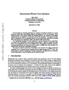
Pigs Pigging use several nondestructive testing methods to perform the inspections. Most pigging use a magnetic flux leakage method but some also use ultrasound to perform the inspections. Pigs that use ultrasound, have an array of transducers that emits a high frequency sound pulse perpendicular to the pipe wall and receives echo signals from the inner surface and the outer surface of the pipe. The tool measures the time interval between the arrival of a reflected echo's from inner surface and outer surface to calculate the wall thickness.
Dr. Essam Bahgat Moustafa
72
Unpiggable Pipeline A pipeline that can’t be pigged Not all pipelines can be successfully pigged – Companies strive to make their pigs work perfectly the first time. – Achieve this 90% of the time. Many pipelines were built before pigs were first used – In the 1970’s, only 30% of interstate gas pipelines could be pigged. What makes lines Unpiggable? Small diameters Flow and access Bends and Connections Older Pipelines Dr. Essam Bahgat Moustafa
73
Launching/ receiving trap design and dimensions
Dr. Essam Bahgat Moustafa
74
Gel pigs & Pigging
Dr. Essam Bahgat Moustafa
75
Dr. Essam Bahgat Moustafa
76
In-line inspection pigging
Dr. Essam Bahgat Moustafa
77
Magnetic flux leakage [MFL] Metal loss services
Dr. Essam Bahgat Moustafa
78
Ultrasonic [UT]
Dr. Essam Bahgat Moustafa
79
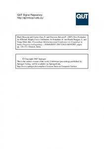
Pigging Application in Corrosion Control Prevention
Prevention
Batching pigs •By-pass pigs
Detection Photographic / video inspection
Detection
Monitoring Monitoring
Dr. Essam Bahgat Moustafa
Magnetic Flux Leakage(MFL) • Ultrasonic (UT) •Eddy Currents 80
Dr. Essam Bahgat Moustafa
81
THANK YOU Presented by:
Dr. Essam Bahgat For any Enquiry:
[email protected] Dr. Essam Bahgat Moustafa
82